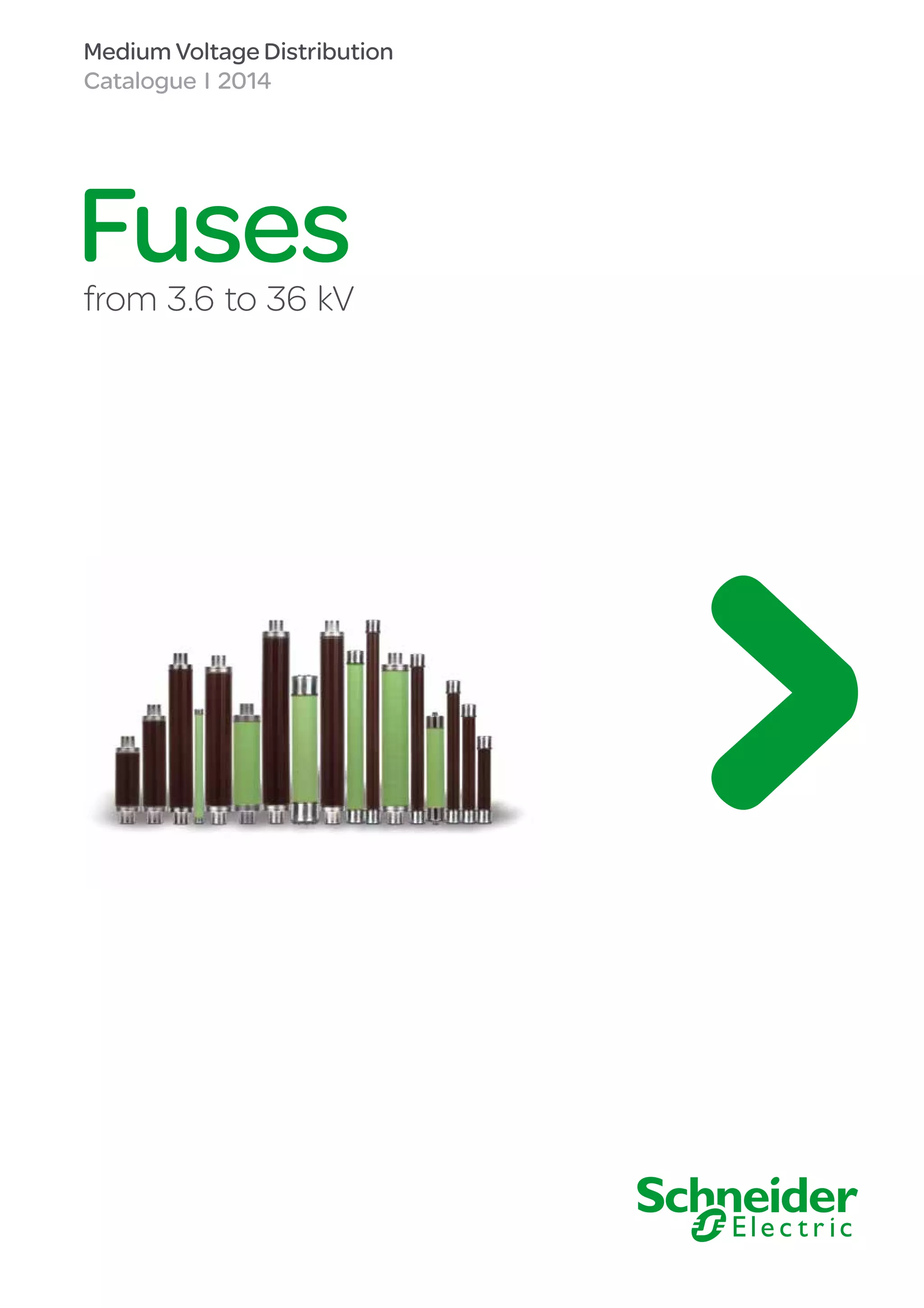
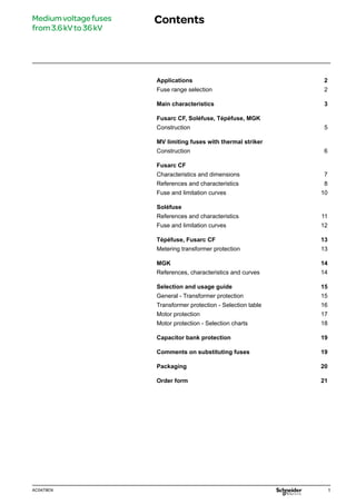
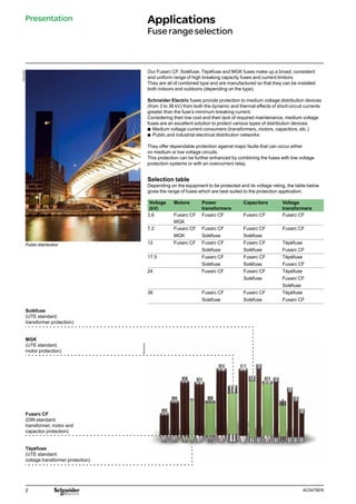
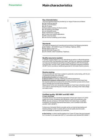
Fuses
from 3.6 to 36 kV
Medium Voltage Distribution
Catalogue I 2014
CÔNG TY CỔ PHẦN THIẾT BỊ ĐIỆN HOÀNG PHƯƠNG
ĐC: Số 10, ngõ 44, phố Võ Thị Sáu, P.Thanh Nhàn, Q.Hai Bà Trưng, TP. Hà Nội
MST: 0106798886
Tel: 024.3215.1322
Website: Hoangphuong.com.vn
Phone/Zalo: 0944.240.317 / 0975.123.698 / 0961.008.858
Email: Codienhoangphuong@gmail.com
1
AC0479EN
Mediumvoltagefuses
from3.6kVto36kV
Contents
Applications 2
Fuse range selection 2
Main characteristics 3
Fusarc CF, Soléfuse, Tépéfuse, MGK
Construction 5
MV limiting fuses with thermal striker
Construction 6
Fusarc CF
Characteristics and dimensions 7
References and characteristics 8
Fuse and limitation curves 10
Soléfuse
References and characteristics 11
Fuse and limitation curves 12
Tépéfuse, Fusarc CF 13
Metering transformer protection 13
MGK 14
References, characteristics and curves 14
Selection and usage guide 15
General - Transformer protection 15
Transformer protection - Selection table 16
Motor protection 17
Motor protection - Selection charts 18
Capacitor bank protection 19
Comments on substituting fuses 19
Packaging 20
Order form 21
2 AC0479EN
Soléfuse
(UTE standard;
transformer protection)
MGK
(UTE standard;
motor protection)
Fusarc CF
(DIN standard;
transformer, motor and
capacitor protection)
Tépéfuse
(UTE standard;
voltage transformer protection)
PM103057
Public distribution
PM103181
Our Fusarc CF, Soléfuse, Tépéfuse and MGK fuses make up a broad, consistent
and uniform range of high breaking capacity fuses and current limitors.
They are all of combined type and are manufactured so that they can be installed
both indoors and outdoors (depending on the type).
Schneider Electric fuses provide protection to medium voltage distribution devices
(from 3 to 36 kV) from both the dynamic and thermal effects of short-circuit currents
greater than the fuse’s minimum breaking current.
Considering their low cost and their lack of required maintenance, medium voltage
fuses are an excellent solution to protect various types of distribution devices:
b
b Medium voltage current consumers (transformers, motors, capacitors, etc.)
b
b Public and industrial electrical distribution networks.
They offer dependable protection against major faults that can occur either
on medium or low voltage circuits.
This protection can be further enhanced by combining the fuses with low voltage
protection systems or with an overcurrent relay.
Selection table
Depending on the equipment to be protected and its voltage rating, the table below
gives the range of fuses which are best suited to the protection application.
Voltage
(kV)
Motors Power
transformers
Capacitors Voltage
transformers
3.6 Fusarc CF Fusarc CF Fusarc CF Fusarc CF
MGK
7.2 Fusarc CF Fusarc CF Fusarc CF Fusarc CF
MGK Soléfuse Soléfuse
12 Fusarc CF Fusarc CF Fusarc CF Tépéfuse
Soléfuse Soléfuse Fusarc CF
17.5 Fusarc CF Fusarc CF Tépéfuse
Soléfuse Soléfuse Fusarc CF
24 Fusarc CF Fusarc CF Tépéfuse
Soléfuse Fusarc CF
Soléfuse
36 Fusarc CF Fusarc CF Tépéfuse
Soléfuse Soléfuse Fusarc CF
Presentation Applications
Fuserangeselection
3
AC0479EN
Key characteristics
The most significant features provided by our range of fuses are as follows:
b
b High breaking capacity
b
b High current limitation
b
b Low I2t values
b
b Dependable breaking of critical currents
b
b Low breaking overvoltage
b
b Low dissipated power
b
b No maintenance or ageing
b
b For indoor and outdoor applications
b
b With a thermal striker
b
b Low minimum breaking current values.
Standards
Our fuses are designed and manufactured according to the following standards:
b
b IEC 60282-1, IEC 60787 (Fusarc CF, Soléfuse,Tépéfuse, MGK)
b
b DIN 43625 (Fusarc CF)
b
b VDE 0670-402 (Fusarc CF)
b
b UTE C64200, C64210 (Soléfuse, Tépéfuse).
Quality assurance system
In addition to being tested in our own laboratories as well as in official laboratories
such as the CESI, Les Renardiers and Labein, with their own respective certificates,
our fuses are manufactured according to quality guidelines within the framework
of the ISO 9001 and ISO 14001 Quality System Certification awarded by AENOR
(IQ-NET) which provides an additional guarantee for Schneider Electric products.
Routine testing
During manufacture, each fuse is subject to systematic routine testing, with the aim
of checking its quality and conformity:
b
b Dimensional control and weight control
b
b Visual control of markings, labelling and external appearance
b
b Electrical resistance measurement: a key point to ensure that fuses have
the required performance levels at the end of the production process and to check
that no damage has occurred during assembly.
Measurement of the room temperature resistance of each fuse is therefore carried
out in order to check that they are in line with values, according to their rated voltage
and rated current.
Certified quality: ISO 9001 and ISO 14001
A major advantage
Schneider Electric has a functional organisation whose main mission is to check
quality and monitor compliance with standards in each of its production units.
MESA, the only company in Schneider Electric that makes fuses, is certified
by AENOR (The Spanish Standards Association), and is certified to ISO 9001
and ISO 14001 (IQ-NET).
Furthermore, Schneider Electric annually carries out internal type-testing and
breaking testing in order to comply with our annual quality assurance plan,
which is available on request to our customers.
b
b Seal testing: in order to test the sealing of our Fusarc CF fuses, they are immersed
for 5 minutes in a hot water bath (80°C), in accordance with standard IEC 60282-1.
PE55711
Presentation Maincharacteristics
4 AC0479EN
DE55750
Key definitions
Un: rated voltage
This is the highest voltage between phases (expressed in kV) for the network
on which the fuse might be installed.
In the medium voltage range, the preferred rated voltages have been set at:
3.6 - 7.2 - 12 - 17.5 - 24 and 36 kV.
In: rated current
This is the current value that the fuse can withstand on a constant basis without any
abnormal temperature rise (generally 65 Kelvin for the contacts).
I3: minimum rated breaking current
This is the minimum current value which causes the fuse to blow and break
the current. For our fuses, these values are between 3 and 5 times the In value.
Comment: it is not enough for a fuse to blow in order to interrupt the flow of current.
For current values less than I3 , the fuse will blow, but may not break the current.
Arcing continues until an external event interrupts the current. It is therefore
essential to avoid using a fuse in the range between In and I3.
Overcurrents in this range may irreversibly damage fuse elements, whilst still
maintaining the risk of an arc which is not broken, and of them being destroyed.
Figure 1 shows the operating ranges of combined type fuses.
I2: critical currents (currents giving similar conditions to the maximum arcing
energy). This current subjects the fuse to greater thermal and mechanical stresses.
The value of I2 varies between 20 and 100 times the In value, depending on
the design of the fuse element. If the fuse can break this current, it can also break
currents between I3 and I1.
I1: maximum rated breaking current
This is the presumed fault current that the fuse can interrupt. This value is very high for
our fuses ranging from 20 to 63 kA.
Comment: it is necessary to ensure that the network short circuit current is at least
equal to the I1 current of the fuse that is used.
Figure 1: definition of a fuse’s operating zone.
Safe operating
range
Presentation Maincharacteristics
5
AC0479EN
DE58240EN
Figure 2: this graph shows the value
of the force provided by the striker
according to its length of travel.
End contact caps (1)
Together with the enclosure, they form an assembly which must remain intact before,
during and after breaking the current. This is why they have to withstand mechanical
stresses and sealing stresses due to overpressure caused by arcing. The stability of
the internal components must also be ensured over time.
Enclosure (2)
This part of the fuse must withstand certain specific stresses (related to what
has already been mentioned):
b
b Thermal stresses: the enclosure has to withstand the rapid temperature rise
that occurs when the arc is extinguished
b
b Electrical stresses: the enclosure has to withstand the restoring of current after
breaking
b
b Mechanical stresses: the enclosure has to withstand the increase in pressure
caused by the expansion of the sand when breaking occurs.
Core (3)
This is a cylinder surrounded by ceramic fins onto which the fuse element is wound.
The striker control wire together with the latter are fitted in the cyclinder. They are
insulated from the fuse elements.
Fuse element (4)
This is the main component of the fuse. It is made from materials with very low
resistance and which do not wear over time. Our fuse elements are carefully
configured following a lot of testing, to enable us to achieve the required results.
Extinction powder (5)
The extinction powder is made up of high purity quartzite sand (over 99.7%),
which is free from any metal compounds and moisture.
When it vitrifies, the sand absorbs the energy produced by the arc and forms
an insulating compound called fulgurite with the fuse element.
Thermal striker (6)
This is a mechanical device which indicates correct fuse operation.
It also provides the energy required to actuate a combined breaking device.
The striker is controlled by a heavy duty wire which, once the fuse element
has blown, also melts and releases the striker. It is very important that the control
wire does not cause premature tripping of the striker, nor must it interfere with
the breaking process.
The Schneider Electric limiting fuse, with its thermal striker, is not only capable
of indicating and breaking short circuits. It is also capable of this for prolonged
overcurrents, and currents causing significant temperature rises in the devices
combined with the fuses and the fuses themselves.
The thermal strikers installed in our fuses are of “medium type” and their force/travel
characteristics (approximately 1 joule according to standard IEC-60282-1) are shown
in figure 2.
PE55712
1  Contact caps
2 Enclosure
3 Core
4  Fuse element
5  Extinction powder
6  Thermal striker
PE55713
Figure 3: cross sectional diagram of a fuse
80
70
60
50
40
30
20
10
0
0 5 10 15 20 23 Travel
(mm)
Force (N)
Fuses FusarcCF,Soléfuse,Tépéfuse,MGK
Construction
6 AC0479EN
All Schneider Electric fuses (type Fusarc CF) are provided of a thermal protection
device. In the case of permanent overcurrents lower than I3 and superior to the rated
current (In), the fuse mechanical striker acts opening the device associated and
avoiding any incidents due to overheatings.
In this way, the fuse not only works as a current limiter but also as a temperature
limiter when combined with an external breaking device.
These types of fuses, which integrate a thermal striker, are fully compatible with
standard Back UP type fuses.
Figure 1.1 shows thermal protection action zone.
Technical / economic / safety advantages:
The use of a thermal protector in our fuses provides the following advantages:
b
b Protecting the fuses and their environment from unacceptable temperature rises
in installations equipped with a disconnecting switch with the possibility of automatic
opening
b
b Providing a response to unexpected operating conditions, to frequent or longlasting
overloads, or to mistakes in selecting the fuse rating, or even concerning restricted
ventilation conditions within the installation
b
b Indicating and protecting against overloads caused by overcurrents below the
minimum breaking current (I3) of the installed fuse and which can cause dangerous
operating temperatures
b
b Reducing operating costs due to destruction of equipment or excess costs caused
by loss of quality of service (repair time, staff, etc.).
This thermal protector safety feature, significantly reduces the risk of damage
and accidents in installations and therefore increases the power distribution quality
of service.
The characteristics of the thermal striker fuse (breaking capacity, fuse curves,
limiting values, striker force, etc.) do not vary relative to our fuses without
thermal protection.
SM6 RMU with CF fuses
DE55754
Figure 1.1: thermal protection
Thermal striker
action zone
Fuses MVlimitingfuses
withthermalstriker
Construction
058630N
7
AC0479EN
Fusarc CF
This is Schneider Electric’s DIN standard fuse range.
When designing this range, we paid particular attention to minimise power dissipation.
It is increasingly common to use RMU units with SF6 gas as the insulating material.
In view of these operating conditions, in which the fuse is inserted inside a
hermetically sealed fuse chamber, with virtually no ventilation, these fuses avoid
premature ageing of themselves and of the whole device which would otherwise
be caused by a non-optimised fuse.
The enclosure in the Fusarc CF range up to 100 A (rated current) is made from
crystallised brown porcelain which withstands ultra-violet radiation and can therefore
be installed both outdoors and indoors.
Fuses with rated current values greater than 100 A have glass fibre enclosures
and are only for indoor installations.
You will find the full list of the Fusarc CF range in the table given on the following page.
With rated voltages ranging from 3 to 36 kV and rated currents of up to 250 A,
they meet customers’ exact requirements in terms of switchgear short-circuit
protection.
Time/current fuse curves
These curves show the virtual fusion or pre-arcing time, as a function of the value
of the symmetrical component of the intended current. Careful selection and design
of fuse elements, together with meticulous industrial control, provides Schneider
Electric customers with precise time-current curves, well above the tolerance limits
provided for in standard IEC 60282-1.
When designing our Fusarc CF fuses, we focused on a relatively high fusion current at
0.1 s in order to withstand transformer making currents and at the same time
a low fusion current at 10 s in order to achieve quick breaking in the case of a fault.
On page 10, we give the time/current characteristics of Fusarc CF fuses.
Current limitation curves
Schneider Electric fuses are current limiting. Consequently, short circuit currents are
limited without reaching their maximum value. These diagrams show the relationship
between the presumed short-circuit current and the peak value of the current broken
by the fuse. The intersection of these lines with straight lines for Imax symmetrical
and Imax asymmetrical give the presumed breaking current, below which fuses
no longer have their limiting capacity.
For example, as shown in the limitation curves on page 10, for a short-circuit whose
presumed current is 5 kA, in an unprotected installation, the maximum current value
would be 7 kA for symmetrical flow and 13 kA for an asymmetrical case.
If we had used a Fusarc CF fuse with a rated current of 16 A, the maximum value
reached would have been 1.5 kA.
PE40483_NE_IQI
Fuses FusarcCF
Characteristicsanddimensions
RM6 RMU with CF fuses
PM103171
* The following page gives the diameter and length
of the fuse according to its rating.
33
23
33
L*
Ø45
Ø6
Ø*
DE55753
Dimensions (mm)
Figure 4 Striker
8 AC0479EN
* Resistances are given at ±10% for a temperature of 20°C.
**Fuses>100A rated current, are manufactured in glass fibre (for indoor use).
For fuses without thermal stricker, please contact the Sales Department.
Fuses FusarcCF
Referencesandcharacteristics
Table no. 1
Reference Rated
voltage (kV)
Operating
voltage (kV)
Rated
current (A)
Max. breaking
current I1 (kA)
Min. breaking
current I3 (A)
Cold resistance*
(m )
Dissipated
power (W)
Length
(mm)
Diameter
(mm)
Weight
(kg)
757372AR** 3,6 3/3,6 250 50 2000 0,626 58 292 86 3,4
51311006M0
7,2 3/7,2
4
63
20 796 20
51006500M0 6,3 36 186,4 12
51006501M0 10 39 110,5 14 1
51006502M0 16 50 68,5 26
50,5
51006503M0 20 62 53,5 32
51006504M0 25 91 36,4 35
51006505M0 31,5 106 26 42 192 1,3
51006506M0 40 150 18 46
51006507M0 50 180 12,4 44
51006508M0 63 265 9,9 52
76 2,1
51006509M0 80 280 7,4 68
51006510M0 100 380 6,2 85
51100049MB 6,3 36 186,4 12
292
50,5 1,2
51100049MC 10 39 110,5 14
51100049MD 16 50 68,5 26
51100049ME 20 62 53,5 32
51100049MF 25 91 36,47 35
51100049MG 31,5 106 26,05 42
51100049MH 40 150 18,06 46
51100049MJ 50 180 12,46 44
76 3,2
51100049MK 63 265 9,9 52
51100049ML 80 280 7,4 68
51100049MM 100 380 6,2 85
757352BN 125 650 3,4 88
757352BP** 160 1000 2,2 87 292
86
3,4
757352BQ** 200 50 1400 1,8 95
757374BR** 250 2200 0,96 95 442 5
51311007M0 4 20 1177 27
51006511M0 6,3 36 283,4 16
51006512M0 10 39 165,5 18 1,2
51006513M0 16 50 106 37
50,5
51006514M0 20 62 82 42
51006515M0 25 91 56 52
51006516M0 31,5 63 106 40 59 292 1,8
51006517M0 12 6/12 40 150 28 74
51006518M0 50 180 18,5 70
51006519M0 63 265 14,8 82
76 3,2
51006520M0 80 280 11,1 102
51006521M0 100 380 8,9 120
757364CN** 125 650 5,3 143
757354CP** 160 40 1000 3,5 127 442 86 5
757354CQ** 200 1400 2,7 172
51006522M0 10 39 233,4 23
50,5 1,2
51006523M0 16 50 146 47
51006524M0 25 91 78,7 72 292
51006525M0 31,5 106 56,6 78 76 3,2
51006526M0 40 150 39,2 90
51311008M0 4 20 1487 34
51006527M0 6,3 40 36 369,3 21
51006528M0 10 39 212,2 25 1,5
51006529M0 17,5 10/17,5 16 50 132 46
50,5
51006530M0 20 62 103 52
51006531M0 25 91 71 66
51006532M0 31,5 106 51 74 367 2,2
51006533M0 40 150 35 94
51006534M0 50 180 23,4 93
51006535M0 63
31,5
265 19,4 121 76 3,9
51006536M0 80 330 13,5 145
51006537M0 100 450 11 192 86 4,6
9
AC0479EN
Table no. 1 (continued)
Reference Rated
voltage (kV)
Operating
voltage (kV)
Rated
current (A)
Max. breaking
current I1 (kA)
Min. breaking
current I3 (A)
Cold resistance*
(mW)
Dissipated
power (W)
Length
(mm)
Diameter
(mm)
Weight
(kg)
51108915M0 6.3 38 455 26
51108916M0 10 40 257.3 35
50.5 1.2
51108917M0 16 60 158 64
51108918M0 20 73 123 84
51108919M0 25 31.5 100 88 79 292
76 3.2
51108920M0 31.5 112 61 90
51108921M0 40 164 45 120
51108922M0 50 233 30 157 86 5
51108923M0 63 247 23 177
51108807M0 6.3 36 455 26
51108808M0 16 50 158 58 50.5 1.5
51108813M0 20 62 123 67 367
51108814M0 25 91 88 76
51108809M0 24 10/24 31.5 106 61 93 76 3.9
51108810M0 40 150 44.5 115
51311009M0 4 40 20 1505 34
51006538M0 6.3 36 455 25
51006539M0 10 39 257.5 31
51006540M0 16 50 158 58
442 50.5 1.7
51006541M0 20 62 123 67
51006542M0 25 91 88 79
51006543M0 31.5 106 61 96
51006544M0 40 150 44.5 119
51006545M0 50 180 33.6 136
51006546M0 63
31.5
265 25.2 144 76 4.5
51006547M0 80 330 18 200
51006548M0 100 450 13.5 240 86 5.7
51311010M0 4 20 20 2209 51
51006549M0 6.3 36 714 39
51006550M0 10 39 392.2 50
50.5 1.9
51006551M0 16 50 252 98
51006552M0
36 20/36
20
40
62 197 120
537
51006553M0 25 91 133 133
51006554M0 31.5 106 103 171
76 5.4
51006555M0 40 150 70 207
51006556M0 50 20 200 47 198
86 6.5
51006557M0 63 250 35 240
Fuses FusarcCF
Referencesandcharacteristics
* Resistances are given at ±10% for a temperature of 20°C.
For fuses without thermal stricker, please contact the Sales Department.
10 AC0479EN
DE58241
Time/current characteristics curves
3.6 - 7.2 - 12 - 17.5 - 24 - 36 kV
Time (s)
Current limitation curves 3.6 - 7.2 - 12 - 17.5 - 24 - 36 kV
Maximum value of cut-off current (kA peak)
DE58242
10
2 4 6 8 2 4 6 8 2 4 8
6
10000
1000
100
0.01
2
4
6
8
2
4
6
8
2
4
6
0.1
10
1
8
8
6
100
4
2
1000
8
6
4
2
10
A
6.3
A
16
A
20
A
25
A
31.5
A
50
A
63
A
80
A
100
A
160
A
200
A
250
A
4
A
125
A
40
A
0.1
2
100
2
4
1
10
10
1
0.1
6
8
2
4
6
8
100
2
4
8
6
4 6 8
6 8 2 4 6 8 2 4 6 8
50 A
250 A
200 A
160 A
125 A
4 A
100 A
63 A
80 A
40 A
16 A
20 A
6.3 A
25 A
10 A
31.5 A
Is
=
Ik
2
Ia
=
1.8
Ik
2
Rms value of the presumed broken current (kA)
Current (A)
The diagram shows the maximum limited broken current value
as a function of the rms current value which could
have occurred in the absence of a fuse.
Fuses FusarcCF
Fuseandlimitationcurves
PM103172
11
AC0479EN
DE55752
23 max.
450
35
520
Ø55
Ø6
Dimensions (mm)
Figure 5	 Striker
Weight: 2.3 kg
The Soléfuse range of fuses is manufactured according to UTE standard C64200.
The rated voltage varies from 7.2 to 36 kV. They can be supplied with or without
a striker and their weight is of around 2 kg.
They are mainly intended to protect power transformers and distribution networks,
and are solely for indoor installations (glass fibre enclosure).
Electrical characteristics
Fuses Soléfuse
Referencesandcharacteristics
* Resistances are given at ±10% for a temperature of 20°C.
** Without striker.
Table no. 2
Reference Rated
voltage
(kV)
Operating
voltage
(kV)
Rated
current
(A)
Min. breaking
current
I3 (A)
Max. breaking
current
I1 (kA)
Cold
resistance *
(mΩ)
Power
Dissipation
values (W)
757328 BC 6,3 35 192,7 11
757328 BE 16 80 51,7 23
757328 BH 7,2 3/7,2 31,5 157,5 50 24,5 49
757328 BJ 43 215 16,15 59
757328 BK 63 315 11,3 84
757328 BN 125 625 4,8 140
757328 CM 7,2/12 3/12 100 500 50 7,7 143
757328 DL 7,2/17,5 3/17,5 80 400 40 15,1 180
757328 EC 6,3 35 454,3 30
757328 ED 10 50 241,9 31
757328 EE 16 80 95,6 41
757328 EG 25 125 69,1 58
757328 EH 12/24 10/24 31,5 157,5 31,5 45,77 81
757328 EJ 43 215 33,6 128
757328 EL 50 250 37 156
757328 EK 63 315 19,9 147
757331 GC** 6,3 35 463 35
757331 GD** 10 50 244,6 31
757331 GE** 16 80 96 41
757331 GG** 25 125 69,3 58
757331 GH** 12/24 10/24 31,5 157,5 31,5 46,2 81
757331 GJ** 43 215 34,3 128
757331 GL** 50 250 37 156
757331 GK** 63 315 19,9 150
757328 FC 6,3 35 762,6 42
757328 FD 10 50 252,9 43
757328 FE 36 30/36 16 80 20 207,8 92
757328 FF 20 100 133,2 93
757328 FG 25 125 124 136
757328 FH 31,5 157,5 93 172
12 AC0479EN
Time/current characteristic curves 7.2 - 12 - 17.5 - 24 - 36 kV
DE58244
The diagram shows the maximum limited broken current value
as a function of the rms current value which could
have occurred in the absence of a fuse.
Fuses Soléfuse
Fuseandlimitationcurves
Current limitation curves 7.2 - 12 - 17.5 - 24 - 36 kV
Maximum value of cut-off current (kA peak)
DM103259
Current (A)
Time (s)
10
2 4 6 8
100
2 4 6 8
1000
2 4 6 8
10000
1000
100
10
8
6
4
2
8
6
4
2
8
6
4
2
1
8
6
4
2
0,1
8
6
4
2
0,01
6,3
A
10
A
10
A
(36kV)
16
A
(36kV)
20
A
25
A
16
A
31,5
A
43
A
63
A
50
A
80
A
100
A
125
A
Rms value of the presumed broken current (kA)
6 8
4
2 6 8
4
2 6 8
4
2
0.1
0.1
1 10 100
10
8
6
4
2
8
6
4
2
8
6
4
2
1
100
125 A
100 A
80 A
63 A
43 A
31.5 A
10 A
16 A
20 A
25 A
6.3 A
Is
=
Ik
2
Ia
=
1.8
Ik
2
Time (s)
13
AC0479EN
Current (A)
We manufacture Tépéfuse and Fusarc CF type fuses intended for metering
transformer protection which have the following references and characteristics:
Characteristics
* Resistances are given at ±10% for a temperature of 20°C.
Tépéfuse fuses are only made in glass fibre when intended for indoor usage.
Fuses for metering transformer protection are made without strikers, according to figures 6 and 7.
Dimensions (mm)
Fusarc CF (Figure 6)
DE55759
PM103171
DE55760
Tépéfuse (Figure 7)
301
15
331
Ø27.5
33 L
Ø 45 Ø 50.5
Fuse curve 7.2 - 12 - 24 - 36 kV
Time (s)
DE58245
1
2 4 6 8
10
2 4 6 8
100
1000
8
6
4
2
100
8
6
4
2
10
8
6
4
2
1
8
6
4
2
0.1
8
6
4
2
0.01
1
A
(Fusarc
CF)
0.3
A
(Tépéfuse)
2.5
A
(Fusarc
CF)
Current (A)
Fuses Tépéfuse,FusarcCF
(meteringtransformerprotection)
References,characteristicsandcurves
PM103174
Table no. 3
Type Reference Rated
voltage
(kV)
Operating
voltage
(kV)
Rated
current
(A)
Max. breaking
current
I1 (kA)
Min. breaking
current
I3 (A)
Cold
resistance *
(mW)
Length
(mm)
Diameter
(mm)
Weight
(kg)
Tépéfuse 781825A 12 < 12
0.3 40 40
6.1
301 27.5 0.4
781825B 24 13.8/24 11.6
Fusarc CF 51311002M0 7.2 3/7.2 2.5 1278 192 0.9
51311000M0
12 6/12
1 63 3834
292 1.2
51311003M0 2.5 1917
51311011M0 17.5 10/17.5 2.5 9.5 2407 367 50.5 1.5
51311001M0
24 10/24
1 40 4815
442 1.6
51311004M0 2.5 2407
51311005M0 36 20/36 2.5 20 3537 537 1.8
14 AC0479EN
DE55761
Ø 81
438
55
Weight: 4.1 kg
MGK fuses are intended to protect medium voltage motors at 7.2 kV
(indoor application).
Electrical characteristics
Table no. 4
Reference Rated
voltage
(kV)
Operating
voltage
(kV)
Rated
current
(A)
Min. breaking
current
I3 (A)
Max. breaking
current
I1 (kA)
Cold
resistance *
(mW)
757314 100 360 50 6.4
757315 125 570 50 4.6
757316 7.2 y 7.2 160 900 50 2.4
757317 200 1400 50 1.53
757318 250 2200 50 0.98
* Resistances are given at ±10% for a temperature of 20°C.
Fuse curve 7.2 kV
Time (s)
DE58246
10
2 4 6 8
100
2 4 6 8
1000
2 4 6 8
10000
1000
8
6
4
2
100
8
6
4
2
10
8
6
4
2
1
8
6
4
2
0.1
8
6
4
2
0.01
100
A
125
A
160
A
200
A
250
A
Current limitation curve 7.2 kV
Maximum value of limited broken current (kA peak)
The diagram shows the maximum limited broken current value
as a function of the rms current value which could
have occurred in the absence of a fuse.
DE58247
6 8
4
2 6 8
4
2 6 8
4
2
0.1
0.1
1 10 100
10
8
6
4
2
8
6
4
2
8
6
4
2
1
100
250 A
200 A
160 A
125 A
100 A
Is
=
Ik
2
Ia
=
1.8
Ik
2
Current (A)
Rms value of presumed broken current (kA)
Fuses MGK
References,characteristicsandcurves
PM103173
Dimensions (mm)
Figure 8	
Striker
15
AC0479EN
(1) In this current zone, any overloads must be eliminated
by LV protection devices or by a MV switch equipped with
an overcurrent relay.
I3
In
In
I
Icc
(1)
	Fuse	 Transformer
Short circuit
current
Closing
DE55764
General
According to their specific characteristics, the various types of fuses (Fusarc CF,
Soléfuse, Tépéfuse and MGK) provide real protection for a wide variety of medium
and high voltage equipment (transformers, motors, capacitors).
It is of the utmost importance to always remember the following points:
b
b Un of the fuse must be greater than or equal to the network voltage
b
b I1 of a fuse must be greater than or equal to the network short circuit current
b
b The characteristics of the equipment to be protected must always be taken into
consideration.
Transformer protection
Atransformer imposes three main stresses on a fuse. This is why the fuses must be
capable of:
b
b … Withstanding the peak start-up current which accompanies transformer
closing
The fuses’ fusion current at 0.1 s must be more than 12 times the transformer’s rated
current.
If(0.1 s) > 12 x In transfo.
b
b … Breaking fault currents across the terminals of the transformer secondary
A fuse intended to protect a transformer has to break its rated short circuit current
(Isc) before it can damage the transformer.
Isc > If(2 s)
b
b … Withstanding the continuous operating current together with possible
overloads
In order to achieve this, the fuse’s rated current must be over 1.4 times
the transformer’s rated current.
In fuse > 1.4 In transfo.
Choice of rating
In order to correctly select the fuse’s rated current to protect a transformer,
we have to know and take account of:
b
b The transformer characteristics:
v
v power (P in kVA)
v
v short circuit voltage (Usc in %)
v
v rated current.
b
b The fuse characteristics:
v
v time/current characteristics (If 0.1 s and If 2 s)
v
v the minimum rated breaking current (I3).
b
b The installation and operating conditions:
v
v open air, cubicle or fuse chamber
v
v presence or otherwise of permanent overload
v
v short circuit current in the installation
v
v indoor or outdoor usage.
Comment: whether used in Schneider Electric’s SM6, RM6, CAS 36 or in a device from
another manufacturer, the equipment manufacturer’s own user’s instructions must be
referred to when choosing the fuse.
Fuses Selectionandusageguide
General
Transformerprotection
16 AC0479EN
Fusarc CF fuses DIN standard for transformer protection (rating in A) (1) (2) (3)
Table no. 6
Operating
voltage
(kV)
Rated
voltage
(kV)
Transformer power
(kVA)
25 50 75 100 125 160 200 250 315 400 500 630 800 1000 1250 1600 2000
16 25 31.5 40 50 63 63 80
3 7.2 20 31.5 40 50 63 80 80 100 100 125 125 160 200 250
25 40 50 63 80 100 100 125 160 160
16 25 31.5 31.5 40 50 63 63 80
5 7.2 10 20 31.5 40 40 50 63 80 80 100 100 125 125 160 200 250
16 25 40 50 50 63 80 100 100 125 160 160
6.3 16 20 25 31.5 40 40 50 63 63 80
6 7.2 10 20 25 31.5 40 50 50 63 80 80 100 100 125 125 160 200 250
25 31.5 40 50 63 63 80 100 100 125
6.3 16 20 25 25 31.5 40 50 50 63 80
6.6 7.2 10 20 25 31.5 31.5 40 50 63 63 80 100 100 125 125 160 200 250
25 31.5 40 40 50 63 80 80 100 125
16 20 25 31.5 31.5 40 50 63 63
10 12 6.3 10 16 20 25 31.5 40 40 50 63 80 80 80 100 125 125 160
16 20 25 31.5 40 50 50 63 80 100 100 100 125
10 16 20 25 25 31.5 40 50 50 63
11 12 6.3 10 16 20 25 31.5 31.5 40 50 63 63 80 80 100 125 125 160
20 25 31.5 40 40 50 63 80 80 100 100 125
6.3 10 16 16 20 25 25 31.5 40 50 50 63
13.2 17.5 4 10 16 20 20 25 31.5 31.5 40 50 63 63 80 80 100
25 25 31.5 40 40 50 63 80 80 100 100
6.3 10 10 16 20 25 25 31.5 40 50 50 63
13.8 17.5 4 10 16 16 20 25 31.5 31.5 40 50 63 63 80 80 100 100
20 25 31.5 40 40 50 63 80 80 100 100
10 16 16 25 31.5 40 40 50 63 63 80
15 17.5 4 6.3 10 16 20 20 25 31.5 40 50 50 63 80 80 100 100 100
10 16 20 25 25 31.5 40 50 63 63 80 100
6.3 10 16 16 20 25 31.5 31.5 40 50 63
20 24 6.3 10 10 16 20 20 25 31.5 40 40 50 63 63 80 80 100
16 20 25 25 31.5 40 50 50 63 80 100 100
10 10 16 20 25 25 31.5 40 40 50 63
22 24 6.3 6.3 10 16 16 20 25 31.5 31.5 40 50 50 63 80 80 100
10 20 25 31.5 40 40 50 63 63 80 100 100
6.3 10 16 16 25 31.5 40 40 50
25 36 4 6.3 10 10 16 20 20 25 31.5 40 50 50 63 63 63
10 20 25 25 31.5 40 50 63 63
6.3 10 16 16 25 31.5 31.5 40 50
30 36 4 6.3 6.3 10 10 16 20 20 25 31.5 40 40 50 63 63 63
10 16 20 25 25 31.5 40 50 50 63
Soléfuse fuses UTE standard for transformer protection (rating in A) (1) (2) (3)
Table no. 7
Operating
voltage
(kV)
Rated
voltage
(kV)
Transformer power
(kVA)
25 50 100 125 160 200 250 315 400 500 630 800 1000 1250 1600
3 7.2 16 16 31.5 63 63 63 80 100 100 125
3.3 7.2 16 16 31.5 31.5 63 63 80 80 100 125
4.16 7.2 6.3 16 31.5 31.5 31.5 63 63 80 80 100 125
5.5 7.2 6.3 16 16 31.5 31.5 31.5 63 63 63 80 100 125
6 7.2 6.3 16 16 31.5 31.5 31.5 63 63 63 80 100 100 125
6.6 7.2 6.3 16 16 16 31.5 31.5 31.5 63 63 80 80 100 125
10 12 6.3 6.3 16 16 16 31.5 31.5 31.5 43 43 63 80 80 100
11 12 6.3 6.3 16 16 16 16 31.5 31.5 31.5 43 63 63 80 100
13.8 17.5/24 6.3 6.3 16 16 16 16 16 31.5 31.5 31.5 43 63 63 80
15 17.5/24 6.3 6.3 16 16 16 16 16 31.5 31.5 31.5 43 43 63 80 80
20 24 6.3 6.3 6.3 6.3 16 16 16 16 31.5 31.5 43 43 43 63
22 24 6.3 6.3 6.3 6.3 16 16 16 16 16 31.5 31.5 31.5 43 43 63
30 36 6.3 6.3 6.3 16 16 16 16 16 31.5 31.5 31.5
(1) Fuse ratings correspond to open air installation with a transformer overload of 30%. or to an indoor installation without transformer overload.
(2) If the fuse is incorporated in a distribution switchboard. please refer to the selection table provided by the manufacturer of this device.
(3) although the ratings shown in bold type are the most appropriate. the others also protect transformers in a satisfactory manner.
Fuses Selectionandusageguide
Transformerprotection
Selectiontable
17
AC0479EN
Fusarc CF selection
for motor protection
Table no. 8
Maximum Start-up Start-up time (s)
operating current 5 10 20
voltage
(kV) (A) Number of start-ups per hour
6 12 6 12 6 12
3.3 1410 250
1290 250 250 250
1140 250 250 250 250 250 250
1030 250 250 250 250 250 250
890 250 250 250 250 250 250
790 200 250 250 250 250 250
710 200 200 200 250 250 250
640 200 200 200 200 200 250
6.6 610 200 200 200 200 200 200
540 160 160 160 200 200 200
480 160 160 160 200 200 200
440 160 160 160 160 160 200
310 160 160 160 160 160 160
280 125 160 160 160 160 160
250 125 125 125 160 160 160
240 125 125 125 125 125 160
230 125 125 125 125 125 125
210 100 125 125 125 125 125
180 100 100 100 100 100 125
11 170 100 100 100 100 100 100
160 100 100 100 100 100 100
148 80 100 100 100 100 100
133 80 80 80 100 100 100
120 80 80 80 80 80 100
110 80 80 80 80 80 80
98 63 80 80 80 80 80
88 63 63 63 63 80 80
83 63 63 63 63 63 80
73 50 63 63 63 63 63
67 50 50 50 63 63 63
62 50 50 50 50 50 63
57 50 50 50 50 50 50
Motor protection
When combined with a contactor, fuses provide a particularly effective protection
system for an MV motor.
The specific stresses that fuses have to withstand are due to:
b
b The motor to be protected
b
b The network on which it is placed.
Stresses due to the motor
b
b The start-up current (Id).
b
b The start-up duration (Td).
b
b The number of successive start-ups.
b
b When the motor is energised, and throughout the start-up period, the impedance
of a motor is such that it consumes a current Id which is significantly greater than
the rated load current In. Normally, this current Id is around 6 times the rated current,
(Id/In = 6).
b
b The start-up duration Td depends on the type of load that is being driven by the
motor. It is of around ten seconds.
b
b We also have to take account of the possibility of several successive start-ups
in choosing the fuse rating.
Stresses related to the network
b
b The rated voltage: the rated voltage for MV motors is at most equal to 11 kV.
b
b The limited broken current: networks with MV motors are generally high installed
power networks with very high short circuit currents.
Choice of rating
The fuse rating chosen depends on three parameters:
b
b The start-up current
b
b The duration
b
b The start-up frequency.
Fuses Selectionandusageguide
Motorprotection
18 AC0479EN
The three charts given below enable the fuse rating to be determined when we know
the motor power (P in kW) and its rated voltage (Ua in kV).
Chart 1: this gives the rated current In (A) according to P and Ua.
Chart 2: this gives the start-up current Id (A) according to In (A).
Chart 3: this gives the appropriate rating according Id and the start-up
duration time td (s).
Comments
Chart 1 is plotted for a power factor of 0.92 and an efficiency of 0.94.
For values different to this, use the following equation: In =
P
n 3 Ua . p.f.
b
b chart 3 is given in the case of 6 start-ups spread over an hour or 2 successive
startups .
b
b For n successive start-ups (n > 6), multiply td by
n
6
For p successive start-ups (p > 2), multiply td by
p
2
(see selection table)
In the absence of any information, take td = 10 s.
b
b if the motor start-up is not direct, the rating obtained using the charts below may
be less than the full load current of the motor. In this case, we have to choose a rating
20% over the value of this current, to take account of the cubicle installation.
Fuses with a rating chosen using these charts will satisfy fuse ageing tests according
to recommendations in IEC 60644.
160A
1650 kW
1650 kW
1000 10000
P (kW)
P (kW)
100
10
In
(A)
In
(A)
11kV
10kV
6.6kV
6kV
5.5kV
4.16kV
3.3kV
3kV
100
100
1000
1000 10000 10
167 A
167 A
1000
100
100
10000
B
A
C
1000 A
1000 A
x12
x10
x8
x6
x4
10
10000
1000
100
100
10
10 10
100
2x250A
2x200A
250A
200A
125A
50A
63A
80A
100A
Td
(s)
Td
(s)
Id (A)
Id (A)
A
D
DE58153
Example (in blue in the charts)
A 1650 kW motor powered at 6.6 kV

(point A, chart 1) has a current of 167 A (point B).
The start-up current, 6 times greater than the rated
current = 1000 A 
(point C, chart 2).
For a start-up time of 10 s, 
chart 3 shows a rating
of 250 A (point D).
h = motor efficiency
Ua = rated motor voltage
Id = start up current
Td = start up time
Fuses Selectionandusageguide
Motorprotection
Selectioncharts
19
AC0479EN
Fuses intended to protect capacitor banks have to withstand special voltages:
b
b When the bank is energised, the inrush current is very high and can lead
to premature ageing or fusion of the fuse element
b
b In service, the presence of harmonics can lead to excessive temperature rise.
Choice of rating
A common rule applied to any switchgear in the presence of capacitor banks
is to derate the rated current by 30 to 40% due to the harmonics which cause
additional temperature rise.
It is recommended to apply a coefficient of between 1.7 and 1.9 to the capacitive
current in order to obtain the appropriate fuse rating, i.e. 1.7 or 1.9 times the rated
current of the bank.
As for transformers, it is necessary to know the rms inrush current value and
its duration.
Fuses
In accordance with recommendation in IEC 60282-1 (Application guide):
« it is recommended to replace all three fuses in a three-phase circuit when
one of them has already blown, unless we are certain that there has been
no overcurrent in the fuses which have not blown ».
Moreover, in this guide, we can find several basic recommendations
for the correct use of this type of fuse.
It is important to take account of the fact that the striker only acts when all of
the fuse elements have blown. However, if the striker has not been activated,
this does not mean that the fuses have not been subject to an overcurrent.
Commentsonsubstitutingfuses
Capacitorbankprotection
20 AC0479EN
Fuses Packaging
Individual packaging
Fuses are packed individually
Solefuse packaging
3 unit per carton.
b
b Dimensions: 55 x 22 x 8 cm
Rest of Fuses
Depending on the type of fuse specified and the quantity ordered packaging may
vary.
Ground Shipping
b
b Carton packaging with wooden pallet.
b
b Dimensions:
v
v 66 x 38 x 42 cm
v
v 120 x 80 x 40 cm
v
v 120 x 80 x 70 cm
Export Shipping
b
b Wooden packaging box
b
b Wooden packaging box with wooden pallet.
The edges of the case are reinforced by metal.
b
b Dimensions:
v
v 64 x 32 x 42 cm
v
v 120 x 80 x 40 cm
v
v 120 x 80 x 70 cm
PM104192
PM104193
PM104194
PM104195
21
AC0479EN
Only one of the boxes (ticked X or filled
by the needed value) have to be considered between each
horizontal line.
Fuses Quantity
Electrical characteristics
Rated voltage (kV)
Operating voltage (kV)
Rated current (A)
Power Transformer Motor (kVA)
Dimensions
Fuse length (mm)
Cap diameter (mm)
Other characteristics
Operating conditions
Open air Cubicle Fuse chamber Other
Standards
Reference
Fuses Orderform
AC0479EN 05-2014
As standards, specifications and designs change from time
to time, please ask for confirmation of the information given
in this publication.
Design: Schneider Electric Industries SAS
Photos: Schneider Electric Industries SAS
Printed: Altavia Connexion - Made in France
35, rue Joseph Monier
CS 30323
F - 92506 Rueil Malmaison Cedex (France)
Tél. : +33 (0)1 41 29 70 00
RCS Nanterre 954 503 439
Capital social 896 313 776 €
www.schneider-electric.com
Schneider Electric Industries SAS
ART.72747
©
Schneider
Electric
Industries
SAS
-
Tous
droits
réservés
This document has been
printed on recycled paper

Fuses mv

  • 1.
    Fuses from 3.6 to36 kV Medium Voltage Distribution Catalogue I 2014 CÔNG TY CỔ PHẦN THIẾT BỊ ĐIỆN HOÀNG PHƯƠNG ĐC: Số 10, ngõ 44, phố Võ Thị Sáu, P.Thanh Nhàn, Q.Hai Bà Trưng, TP. Hà Nội MST: 0106798886 Tel: 024.3215.1322 Website: Hoangphuong.com.vn Phone/Zalo: 0944.240.317 / 0975.123.698 / 0961.008.858 Email: Codienhoangphuong@gmail.com
  • 3.
    1 AC0479EN Mediumvoltagefuses from3.6kVto36kV Contents Applications 2 Fuse rangeselection 2 Main characteristics 3 Fusarc CF, Soléfuse, Tépéfuse, MGK Construction 5 MV limiting fuses with thermal striker Construction 6 Fusarc CF Characteristics and dimensions 7 References and characteristics 8 Fuse and limitation curves 10 Soléfuse References and characteristics 11 Fuse and limitation curves 12 Tépéfuse, Fusarc CF 13 Metering transformer protection 13 MGK 14 References, characteristics and curves 14 Selection and usage guide 15 General - Transformer protection 15 Transformer protection - Selection table 16 Motor protection 17 Motor protection - Selection charts 18 Capacitor bank protection 19 Comments on substituting fuses 19 Packaging 20 Order form 21
  • 4.
    2 AC0479EN Soléfuse (UTE standard; transformerprotection) MGK (UTE standard; motor protection) Fusarc CF (DIN standard; transformer, motor and capacitor protection) Tépéfuse (UTE standard; voltage transformer protection) PM103057 Public distribution PM103181 Our Fusarc CF, Soléfuse, Tépéfuse and MGK fuses make up a broad, consistent and uniform range of high breaking capacity fuses and current limitors. They are all of combined type and are manufactured so that they can be installed both indoors and outdoors (depending on the type). Schneider Electric fuses provide protection to medium voltage distribution devices (from 3 to 36 kV) from both the dynamic and thermal effects of short-circuit currents greater than the fuse’s minimum breaking current. Considering their low cost and their lack of required maintenance, medium voltage fuses are an excellent solution to protect various types of distribution devices: b b Medium voltage current consumers (transformers, motors, capacitors, etc.) b b Public and industrial electrical distribution networks. They offer dependable protection against major faults that can occur either on medium or low voltage circuits. This protection can be further enhanced by combining the fuses with low voltage protection systems or with an overcurrent relay. Selection table Depending on the equipment to be protected and its voltage rating, the table below gives the range of fuses which are best suited to the protection application. Voltage (kV) Motors Power transformers Capacitors Voltage transformers 3.6 Fusarc CF Fusarc CF Fusarc CF Fusarc CF MGK 7.2 Fusarc CF Fusarc CF Fusarc CF Fusarc CF MGK Soléfuse Soléfuse 12 Fusarc CF Fusarc CF Fusarc CF Tépéfuse Soléfuse Soléfuse Fusarc CF 17.5 Fusarc CF Fusarc CF Tépéfuse Soléfuse Soléfuse Fusarc CF 24 Fusarc CF Fusarc CF Tépéfuse Soléfuse Fusarc CF Soléfuse 36 Fusarc CF Fusarc CF Tépéfuse Soléfuse Soléfuse Fusarc CF Presentation Applications Fuserangeselection
  • 5.
    3 AC0479EN Key characteristics The mostsignificant features provided by our range of fuses are as follows: b b High breaking capacity b b High current limitation b b Low I2t values b b Dependable breaking of critical currents b b Low breaking overvoltage b b Low dissipated power b b No maintenance or ageing b b For indoor and outdoor applications b b With a thermal striker b b Low minimum breaking current values. Standards Our fuses are designed and manufactured according to the following standards: b b IEC 60282-1, IEC 60787 (Fusarc CF, Soléfuse,Tépéfuse, MGK) b b DIN 43625 (Fusarc CF) b b VDE 0670-402 (Fusarc CF) b b UTE C64200, C64210 (Soléfuse, Tépéfuse). Quality assurance system In addition to being tested in our own laboratories as well as in official laboratories such as the CESI, Les Renardiers and Labein, with their own respective certificates, our fuses are manufactured according to quality guidelines within the framework of the ISO 9001 and ISO 14001 Quality System Certification awarded by AENOR (IQ-NET) which provides an additional guarantee for Schneider Electric products. Routine testing During manufacture, each fuse is subject to systematic routine testing, with the aim of checking its quality and conformity: b b Dimensional control and weight control b b Visual control of markings, labelling and external appearance b b Electrical resistance measurement: a key point to ensure that fuses have the required performance levels at the end of the production process and to check that no damage has occurred during assembly. Measurement of the room temperature resistance of each fuse is therefore carried out in order to check that they are in line with values, according to their rated voltage and rated current. Certified quality: ISO 9001 and ISO 14001 A major advantage Schneider Electric has a functional organisation whose main mission is to check quality and monitor compliance with standards in each of its production units. MESA, the only company in Schneider Electric that makes fuses, is certified by AENOR (The Spanish Standards Association), and is certified to ISO 9001 and ISO 14001 (IQ-NET). Furthermore, Schneider Electric annually carries out internal type-testing and breaking testing in order to comply with our annual quality assurance plan, which is available on request to our customers. b b Seal testing: in order to test the sealing of our Fusarc CF fuses, they are immersed for 5 minutes in a hot water bath (80°C), in accordance with standard IEC 60282-1. PE55711 Presentation Maincharacteristics
  • 6.
    4 AC0479EN DE55750 Key definitions Un:rated voltage This is the highest voltage between phases (expressed in kV) for the network on which the fuse might be installed. In the medium voltage range, the preferred rated voltages have been set at: 3.6 - 7.2 - 12 - 17.5 - 24 and 36 kV. In: rated current This is the current value that the fuse can withstand on a constant basis without any abnormal temperature rise (generally 65 Kelvin for the contacts). I3: minimum rated breaking current This is the minimum current value which causes the fuse to blow and break the current. For our fuses, these values are between 3 and 5 times the In value. Comment: it is not enough for a fuse to blow in order to interrupt the flow of current. For current values less than I3 , the fuse will blow, but may not break the current. Arcing continues until an external event interrupts the current. It is therefore essential to avoid using a fuse in the range between In and I3. Overcurrents in this range may irreversibly damage fuse elements, whilst still maintaining the risk of an arc which is not broken, and of them being destroyed. Figure 1 shows the operating ranges of combined type fuses. I2: critical currents (currents giving similar conditions to the maximum arcing energy). This current subjects the fuse to greater thermal and mechanical stresses. The value of I2 varies between 20 and 100 times the In value, depending on the design of the fuse element. If the fuse can break this current, it can also break currents between I3 and I1. I1: maximum rated breaking current This is the presumed fault current that the fuse can interrupt. This value is very high for our fuses ranging from 20 to 63 kA. Comment: it is necessary to ensure that the network short circuit current is at least equal to the I1 current of the fuse that is used. Figure 1: definition of a fuse’s operating zone. Safe operating range Presentation Maincharacteristics
  • 7.
    5 AC0479EN DE58240EN Figure 2: thisgraph shows the value of the force provided by the striker according to its length of travel. End contact caps (1) Together with the enclosure, they form an assembly which must remain intact before, during and after breaking the current. This is why they have to withstand mechanical stresses and sealing stresses due to overpressure caused by arcing. The stability of the internal components must also be ensured over time. Enclosure (2) This part of the fuse must withstand certain specific stresses (related to what has already been mentioned): b b Thermal stresses: the enclosure has to withstand the rapid temperature rise that occurs when the arc is extinguished b b Electrical stresses: the enclosure has to withstand the restoring of current after breaking b b Mechanical stresses: the enclosure has to withstand the increase in pressure caused by the expansion of the sand when breaking occurs. Core (3) This is a cylinder surrounded by ceramic fins onto which the fuse element is wound. The striker control wire together with the latter are fitted in the cyclinder. They are insulated from the fuse elements. Fuse element (4) This is the main component of the fuse. It is made from materials with very low resistance and which do not wear over time. Our fuse elements are carefully configured following a lot of testing, to enable us to achieve the required results. Extinction powder (5) The extinction powder is made up of high purity quartzite sand (over 99.7%), which is free from any metal compounds and moisture. When it vitrifies, the sand absorbs the energy produced by the arc and forms an insulating compound called fulgurite with the fuse element. Thermal striker (6) This is a mechanical device which indicates correct fuse operation. It also provides the energy required to actuate a combined breaking device. The striker is controlled by a heavy duty wire which, once the fuse element has blown, also melts and releases the striker. It is very important that the control wire does not cause premature tripping of the striker, nor must it interfere with the breaking process. The Schneider Electric limiting fuse, with its thermal striker, is not only capable of indicating and breaking short circuits. It is also capable of this for prolonged overcurrents, and currents causing significant temperature rises in the devices combined with the fuses and the fuses themselves. The thermal strikers installed in our fuses are of “medium type” and their force/travel characteristics (approximately 1 joule according to standard IEC-60282-1) are shown in figure 2. PE55712 1  Contact caps 2 Enclosure 3 Core 4  Fuse element 5  Extinction powder 6  Thermal striker PE55713 Figure 3: cross sectional diagram of a fuse 80 70 60 50 40 30 20 10 0 0 5 10 15 20 23 Travel (mm) Force (N) Fuses FusarcCF,Soléfuse,Tépéfuse,MGK Construction
  • 8.
    6 AC0479EN All SchneiderElectric fuses (type Fusarc CF) are provided of a thermal protection device. In the case of permanent overcurrents lower than I3 and superior to the rated current (In), the fuse mechanical striker acts opening the device associated and avoiding any incidents due to overheatings. In this way, the fuse not only works as a current limiter but also as a temperature limiter when combined with an external breaking device. These types of fuses, which integrate a thermal striker, are fully compatible with standard Back UP type fuses. Figure 1.1 shows thermal protection action zone. Technical / economic / safety advantages: The use of a thermal protector in our fuses provides the following advantages: b b Protecting the fuses and their environment from unacceptable temperature rises in installations equipped with a disconnecting switch with the possibility of automatic opening b b Providing a response to unexpected operating conditions, to frequent or longlasting overloads, or to mistakes in selecting the fuse rating, or even concerning restricted ventilation conditions within the installation b b Indicating and protecting against overloads caused by overcurrents below the minimum breaking current (I3) of the installed fuse and which can cause dangerous operating temperatures b b Reducing operating costs due to destruction of equipment or excess costs caused by loss of quality of service (repair time, staff, etc.). This thermal protector safety feature, significantly reduces the risk of damage and accidents in installations and therefore increases the power distribution quality of service. The characteristics of the thermal striker fuse (breaking capacity, fuse curves, limiting values, striker force, etc.) do not vary relative to our fuses without thermal protection. SM6 RMU with CF fuses DE55754 Figure 1.1: thermal protection Thermal striker action zone Fuses MVlimitingfuses withthermalstriker Construction 058630N
  • 9.
    7 AC0479EN Fusarc CF This isSchneider Electric’s DIN standard fuse range. When designing this range, we paid particular attention to minimise power dissipation. It is increasingly common to use RMU units with SF6 gas as the insulating material. In view of these operating conditions, in which the fuse is inserted inside a hermetically sealed fuse chamber, with virtually no ventilation, these fuses avoid premature ageing of themselves and of the whole device which would otherwise be caused by a non-optimised fuse. The enclosure in the Fusarc CF range up to 100 A (rated current) is made from crystallised brown porcelain which withstands ultra-violet radiation and can therefore be installed both outdoors and indoors. Fuses with rated current values greater than 100 A have glass fibre enclosures and are only for indoor installations. You will find the full list of the Fusarc CF range in the table given on the following page. With rated voltages ranging from 3 to 36 kV and rated currents of up to 250 A, they meet customers’ exact requirements in terms of switchgear short-circuit protection. Time/current fuse curves These curves show the virtual fusion or pre-arcing time, as a function of the value of the symmetrical component of the intended current. Careful selection and design of fuse elements, together with meticulous industrial control, provides Schneider Electric customers with precise time-current curves, well above the tolerance limits provided for in standard IEC 60282-1. When designing our Fusarc CF fuses, we focused on a relatively high fusion current at 0.1 s in order to withstand transformer making currents and at the same time a low fusion current at 10 s in order to achieve quick breaking in the case of a fault. On page 10, we give the time/current characteristics of Fusarc CF fuses. Current limitation curves Schneider Electric fuses are current limiting. Consequently, short circuit currents are limited without reaching their maximum value. These diagrams show the relationship between the presumed short-circuit current and the peak value of the current broken by the fuse. The intersection of these lines with straight lines for Imax symmetrical and Imax asymmetrical give the presumed breaking current, below which fuses no longer have their limiting capacity. For example, as shown in the limitation curves on page 10, for a short-circuit whose presumed current is 5 kA, in an unprotected installation, the maximum current value would be 7 kA for symmetrical flow and 13 kA for an asymmetrical case. If we had used a Fusarc CF fuse with a rated current of 16 A, the maximum value reached would have been 1.5 kA. PE40483_NE_IQI Fuses FusarcCF Characteristicsanddimensions RM6 RMU with CF fuses PM103171 * The following page gives the diameter and length of the fuse according to its rating. 33 23 33 L* Ø45 Ø6 Ø* DE55753 Dimensions (mm) Figure 4 Striker
  • 10.
    8 AC0479EN * Resistancesare given at ±10% for a temperature of 20°C. **Fuses>100A rated current, are manufactured in glass fibre (for indoor use). For fuses without thermal stricker, please contact the Sales Department. Fuses FusarcCF Referencesandcharacteristics Table no. 1 Reference Rated voltage (kV) Operating voltage (kV) Rated current (A) Max. breaking current I1 (kA) Min. breaking current I3 (A) Cold resistance* (m ) Dissipated power (W) Length (mm) Diameter (mm) Weight (kg) 757372AR** 3,6 3/3,6 250 50 2000 0,626 58 292 86 3,4 51311006M0 7,2 3/7,2 4 63 20 796 20 51006500M0 6,3 36 186,4 12 51006501M0 10 39 110,5 14 1 51006502M0 16 50 68,5 26 50,5 51006503M0 20 62 53,5 32 51006504M0 25 91 36,4 35 51006505M0 31,5 106 26 42 192 1,3 51006506M0 40 150 18 46 51006507M0 50 180 12,4 44 51006508M0 63 265 9,9 52 76 2,1 51006509M0 80 280 7,4 68 51006510M0 100 380 6,2 85 51100049MB 6,3 36 186,4 12 292 50,5 1,2 51100049MC 10 39 110,5 14 51100049MD 16 50 68,5 26 51100049ME 20 62 53,5 32 51100049MF 25 91 36,47 35 51100049MG 31,5 106 26,05 42 51100049MH 40 150 18,06 46 51100049MJ 50 180 12,46 44 76 3,2 51100049MK 63 265 9,9 52 51100049ML 80 280 7,4 68 51100049MM 100 380 6,2 85 757352BN 125 650 3,4 88 757352BP** 160 1000 2,2 87 292 86 3,4 757352BQ** 200 50 1400 1,8 95 757374BR** 250 2200 0,96 95 442 5 51311007M0 4 20 1177 27 51006511M0 6,3 36 283,4 16 51006512M0 10 39 165,5 18 1,2 51006513M0 16 50 106 37 50,5 51006514M0 20 62 82 42 51006515M0 25 91 56 52 51006516M0 31,5 63 106 40 59 292 1,8 51006517M0 12 6/12 40 150 28 74 51006518M0 50 180 18,5 70 51006519M0 63 265 14,8 82 76 3,2 51006520M0 80 280 11,1 102 51006521M0 100 380 8,9 120 757364CN** 125 650 5,3 143 757354CP** 160 40 1000 3,5 127 442 86 5 757354CQ** 200 1400 2,7 172 51006522M0 10 39 233,4 23 50,5 1,2 51006523M0 16 50 146 47 51006524M0 25 91 78,7 72 292 51006525M0 31,5 106 56,6 78 76 3,2 51006526M0 40 150 39,2 90 51311008M0 4 20 1487 34 51006527M0 6,3 40 36 369,3 21 51006528M0 10 39 212,2 25 1,5 51006529M0 17,5 10/17,5 16 50 132 46 50,5 51006530M0 20 62 103 52 51006531M0 25 91 71 66 51006532M0 31,5 106 51 74 367 2,2 51006533M0 40 150 35 94 51006534M0 50 180 23,4 93 51006535M0 63 31,5 265 19,4 121 76 3,9 51006536M0 80 330 13,5 145 51006537M0 100 450 11 192 86 4,6
  • 11.
    9 AC0479EN Table no. 1(continued) Reference Rated voltage (kV) Operating voltage (kV) Rated current (A) Max. breaking current I1 (kA) Min. breaking current I3 (A) Cold resistance* (mW) Dissipated power (W) Length (mm) Diameter (mm) Weight (kg) 51108915M0 6.3 38 455 26 51108916M0 10 40 257.3 35 50.5 1.2 51108917M0 16 60 158 64 51108918M0 20 73 123 84 51108919M0 25 31.5 100 88 79 292 76 3.2 51108920M0 31.5 112 61 90 51108921M0 40 164 45 120 51108922M0 50 233 30 157 86 5 51108923M0 63 247 23 177 51108807M0 6.3 36 455 26 51108808M0 16 50 158 58 50.5 1.5 51108813M0 20 62 123 67 367 51108814M0 25 91 88 76 51108809M0 24 10/24 31.5 106 61 93 76 3.9 51108810M0 40 150 44.5 115 51311009M0 4 40 20 1505 34 51006538M0 6.3 36 455 25 51006539M0 10 39 257.5 31 51006540M0 16 50 158 58 442 50.5 1.7 51006541M0 20 62 123 67 51006542M0 25 91 88 79 51006543M0 31.5 106 61 96 51006544M0 40 150 44.5 119 51006545M0 50 180 33.6 136 51006546M0 63 31.5 265 25.2 144 76 4.5 51006547M0 80 330 18 200 51006548M0 100 450 13.5 240 86 5.7 51311010M0 4 20 20 2209 51 51006549M0 6.3 36 714 39 51006550M0 10 39 392.2 50 50.5 1.9 51006551M0 16 50 252 98 51006552M0 36 20/36 20 40 62 197 120 537 51006553M0 25 91 133 133 51006554M0 31.5 106 103 171 76 5.4 51006555M0 40 150 70 207 51006556M0 50 20 200 47 198 86 6.5 51006557M0 63 250 35 240 Fuses FusarcCF Referencesandcharacteristics * Resistances are given at ±10% for a temperature of 20°C. For fuses without thermal stricker, please contact the Sales Department.
  • 12.
    10 AC0479EN DE58241 Time/current characteristicscurves 3.6 - 7.2 - 12 - 17.5 - 24 - 36 kV Time (s) Current limitation curves 3.6 - 7.2 - 12 - 17.5 - 24 - 36 kV Maximum value of cut-off current (kA peak) DE58242 10 2 4 6 8 2 4 6 8 2 4 8 6 10000 1000 100 0.01 2 4 6 8 2 4 6 8 2 4 6 0.1 10 1 8 8 6 100 4 2 1000 8 6 4 2 10 A 6.3 A 16 A 20 A 25 A 31.5 A 50 A 63 A 80 A 100 A 160 A 200 A 250 A 4 A 125 A 40 A 0.1 2 100 2 4 1 10 10 1 0.1 6 8 2 4 6 8 100 2 4 8 6 4 6 8 6 8 2 4 6 8 2 4 6 8 50 A 250 A 200 A 160 A 125 A 4 A 100 A 63 A 80 A 40 A 16 A 20 A 6.3 A 25 A 10 A 31.5 A Is = Ik 2 Ia = 1.8 Ik 2 Rms value of the presumed broken current (kA) Current (A) The diagram shows the maximum limited broken current value as a function of the rms current value which could have occurred in the absence of a fuse. Fuses FusarcCF Fuseandlimitationcurves PM103172
  • 13.
    11 AC0479EN DE55752 23 max. 450 35 520 Ø55 Ø6 Dimensions (mm) Figure5 Striker Weight: 2.3 kg The Soléfuse range of fuses is manufactured according to UTE standard C64200. The rated voltage varies from 7.2 to 36 kV. They can be supplied with or without a striker and their weight is of around 2 kg. They are mainly intended to protect power transformers and distribution networks, and are solely for indoor installations (glass fibre enclosure). Electrical characteristics Fuses Soléfuse Referencesandcharacteristics * Resistances are given at ±10% for a temperature of 20°C. ** Without striker. Table no. 2 Reference Rated voltage (kV) Operating voltage (kV) Rated current (A) Min. breaking current I3 (A) Max. breaking current I1 (kA) Cold resistance * (mΩ) Power Dissipation values (W) 757328 BC 6,3 35 192,7 11 757328 BE 16 80 51,7 23 757328 BH 7,2 3/7,2 31,5 157,5 50 24,5 49 757328 BJ 43 215 16,15 59 757328 BK 63 315 11,3 84 757328 BN 125 625 4,8 140 757328 CM 7,2/12 3/12 100 500 50 7,7 143 757328 DL 7,2/17,5 3/17,5 80 400 40 15,1 180 757328 EC 6,3 35 454,3 30 757328 ED 10 50 241,9 31 757328 EE 16 80 95,6 41 757328 EG 25 125 69,1 58 757328 EH 12/24 10/24 31,5 157,5 31,5 45,77 81 757328 EJ 43 215 33,6 128 757328 EL 50 250 37 156 757328 EK 63 315 19,9 147 757331 GC** 6,3 35 463 35 757331 GD** 10 50 244,6 31 757331 GE** 16 80 96 41 757331 GG** 25 125 69,3 58 757331 GH** 12/24 10/24 31,5 157,5 31,5 46,2 81 757331 GJ** 43 215 34,3 128 757331 GL** 50 250 37 156 757331 GK** 63 315 19,9 150 757328 FC 6,3 35 762,6 42 757328 FD 10 50 252,9 43 757328 FE 36 30/36 16 80 20 207,8 92 757328 FF 20 100 133,2 93 757328 FG 25 125 124 136 757328 FH 31,5 157,5 93 172
  • 14.
    12 AC0479EN Time/current characteristiccurves 7.2 - 12 - 17.5 - 24 - 36 kV DE58244 The diagram shows the maximum limited broken current value as a function of the rms current value which could have occurred in the absence of a fuse. Fuses Soléfuse Fuseandlimitationcurves Current limitation curves 7.2 - 12 - 17.5 - 24 - 36 kV Maximum value of cut-off current (kA peak) DM103259 Current (A) Time (s) 10 2 4 6 8 100 2 4 6 8 1000 2 4 6 8 10000 1000 100 10 8 6 4 2 8 6 4 2 8 6 4 2 1 8 6 4 2 0,1 8 6 4 2 0,01 6,3 A 10 A 10 A (36kV) 16 A (36kV) 20 A 25 A 16 A 31,5 A 43 A 63 A 50 A 80 A 100 A 125 A Rms value of the presumed broken current (kA) 6 8 4 2 6 8 4 2 6 8 4 2 0.1 0.1 1 10 100 10 8 6 4 2 8 6 4 2 8 6 4 2 1 100 125 A 100 A 80 A 63 A 43 A 31.5 A 10 A 16 A 20 A 25 A 6.3 A Is = Ik 2 Ia = 1.8 Ik 2 Time (s)
  • 15.
    13 AC0479EN Current (A) We manufactureTépéfuse and Fusarc CF type fuses intended for metering transformer protection which have the following references and characteristics: Characteristics * Resistances are given at ±10% for a temperature of 20°C. Tépéfuse fuses are only made in glass fibre when intended for indoor usage. Fuses for metering transformer protection are made without strikers, according to figures 6 and 7. Dimensions (mm) Fusarc CF (Figure 6) DE55759 PM103171 DE55760 Tépéfuse (Figure 7) 301 15 331 Ø27.5 33 L Ø 45 Ø 50.5 Fuse curve 7.2 - 12 - 24 - 36 kV Time (s) DE58245 1 2 4 6 8 10 2 4 6 8 100 1000 8 6 4 2 100 8 6 4 2 10 8 6 4 2 1 8 6 4 2 0.1 8 6 4 2 0.01 1 A (Fusarc CF) 0.3 A (Tépéfuse) 2.5 A (Fusarc CF) Current (A) Fuses Tépéfuse,FusarcCF (meteringtransformerprotection) References,characteristicsandcurves PM103174 Table no. 3 Type Reference Rated voltage (kV) Operating voltage (kV) Rated current (A) Max. breaking current I1 (kA) Min. breaking current I3 (A) Cold resistance * (mW) Length (mm) Diameter (mm) Weight (kg) Tépéfuse 781825A 12 < 12 0.3 40 40 6.1 301 27.5 0.4 781825B 24 13.8/24 11.6 Fusarc CF 51311002M0 7.2 3/7.2 2.5 1278 192 0.9 51311000M0 12 6/12 1 63 3834 292 1.2 51311003M0 2.5 1917 51311011M0 17.5 10/17.5 2.5 9.5 2407 367 50.5 1.5 51311001M0 24 10/24 1 40 4815 442 1.6 51311004M0 2.5 2407 51311005M0 36 20/36 2.5 20 3537 537 1.8
  • 16.
    14 AC0479EN DE55761 Ø 81 438 55 Weight:4.1 kg MGK fuses are intended to protect medium voltage motors at 7.2 kV (indoor application). Electrical characteristics Table no. 4 Reference Rated voltage (kV) Operating voltage (kV) Rated current (A) Min. breaking current I3 (A) Max. breaking current I1 (kA) Cold resistance * (mW) 757314 100 360 50 6.4 757315 125 570 50 4.6 757316 7.2 y 7.2 160 900 50 2.4 757317 200 1400 50 1.53 757318 250 2200 50 0.98 * Resistances are given at ±10% for a temperature of 20°C. Fuse curve 7.2 kV Time (s) DE58246 10 2 4 6 8 100 2 4 6 8 1000 2 4 6 8 10000 1000 8 6 4 2 100 8 6 4 2 10 8 6 4 2 1 8 6 4 2 0.1 8 6 4 2 0.01 100 A 125 A 160 A 200 A 250 A Current limitation curve 7.2 kV Maximum value of limited broken current (kA peak) The diagram shows the maximum limited broken current value as a function of the rms current value which could have occurred in the absence of a fuse. DE58247 6 8 4 2 6 8 4 2 6 8 4 2 0.1 0.1 1 10 100 10 8 6 4 2 8 6 4 2 8 6 4 2 1 100 250 A 200 A 160 A 125 A 100 A Is = Ik 2 Ia = 1.8 Ik 2 Current (A) Rms value of presumed broken current (kA) Fuses MGK References,characteristicsandcurves PM103173 Dimensions (mm) Figure 8 Striker
  • 17.
    15 AC0479EN (1) In thiscurrent zone, any overloads must be eliminated by LV protection devices or by a MV switch equipped with an overcurrent relay. I3 In In I Icc (1) Fuse Transformer Short circuit current Closing DE55764 General According to their specific characteristics, the various types of fuses (Fusarc CF, Soléfuse, Tépéfuse and MGK) provide real protection for a wide variety of medium and high voltage equipment (transformers, motors, capacitors). It is of the utmost importance to always remember the following points: b b Un of the fuse must be greater than or equal to the network voltage b b I1 of a fuse must be greater than or equal to the network short circuit current b b The characteristics of the equipment to be protected must always be taken into consideration. Transformer protection Atransformer imposes three main stresses on a fuse. This is why the fuses must be capable of: b b … Withstanding the peak start-up current which accompanies transformer closing The fuses’ fusion current at 0.1 s must be more than 12 times the transformer’s rated current. If(0.1 s) > 12 x In transfo. b b … Breaking fault currents across the terminals of the transformer secondary A fuse intended to protect a transformer has to break its rated short circuit current (Isc) before it can damage the transformer. Isc > If(2 s) b b … Withstanding the continuous operating current together with possible overloads In order to achieve this, the fuse’s rated current must be over 1.4 times the transformer’s rated current. In fuse > 1.4 In transfo. Choice of rating In order to correctly select the fuse’s rated current to protect a transformer, we have to know and take account of: b b The transformer characteristics: v v power (P in kVA) v v short circuit voltage (Usc in %) v v rated current. b b The fuse characteristics: v v time/current characteristics (If 0.1 s and If 2 s) v v the minimum rated breaking current (I3). b b The installation and operating conditions: v v open air, cubicle or fuse chamber v v presence or otherwise of permanent overload v v short circuit current in the installation v v indoor or outdoor usage. Comment: whether used in Schneider Electric’s SM6, RM6, CAS 36 or in a device from another manufacturer, the equipment manufacturer’s own user’s instructions must be referred to when choosing the fuse. Fuses Selectionandusageguide General Transformerprotection
  • 18.
    16 AC0479EN Fusarc CFfuses DIN standard for transformer protection (rating in A) (1) (2) (3) Table no. 6 Operating voltage (kV) Rated voltage (kV) Transformer power (kVA) 25 50 75 100 125 160 200 250 315 400 500 630 800 1000 1250 1600 2000 16 25 31.5 40 50 63 63 80 3 7.2 20 31.5 40 50 63 80 80 100 100 125 125 160 200 250 25 40 50 63 80 100 100 125 160 160 16 25 31.5 31.5 40 50 63 63 80 5 7.2 10 20 31.5 40 40 50 63 80 80 100 100 125 125 160 200 250 16 25 40 50 50 63 80 100 100 125 160 160 6.3 16 20 25 31.5 40 40 50 63 63 80 6 7.2 10 20 25 31.5 40 50 50 63 80 80 100 100 125 125 160 200 250 25 31.5 40 50 63 63 80 100 100 125 6.3 16 20 25 25 31.5 40 50 50 63 80 6.6 7.2 10 20 25 31.5 31.5 40 50 63 63 80 100 100 125 125 160 200 250 25 31.5 40 40 50 63 80 80 100 125 16 20 25 31.5 31.5 40 50 63 63 10 12 6.3 10 16 20 25 31.5 40 40 50 63 80 80 80 100 125 125 160 16 20 25 31.5 40 50 50 63 80 100 100 100 125 10 16 20 25 25 31.5 40 50 50 63 11 12 6.3 10 16 20 25 31.5 31.5 40 50 63 63 80 80 100 125 125 160 20 25 31.5 40 40 50 63 80 80 100 100 125 6.3 10 16 16 20 25 25 31.5 40 50 50 63 13.2 17.5 4 10 16 20 20 25 31.5 31.5 40 50 63 63 80 80 100 25 25 31.5 40 40 50 63 80 80 100 100 6.3 10 10 16 20 25 25 31.5 40 50 50 63 13.8 17.5 4 10 16 16 20 25 31.5 31.5 40 50 63 63 80 80 100 100 20 25 31.5 40 40 50 63 80 80 100 100 10 16 16 25 31.5 40 40 50 63 63 80 15 17.5 4 6.3 10 16 20 20 25 31.5 40 50 50 63 80 80 100 100 100 10 16 20 25 25 31.5 40 50 63 63 80 100 6.3 10 16 16 20 25 31.5 31.5 40 50 63 20 24 6.3 10 10 16 20 20 25 31.5 40 40 50 63 63 80 80 100 16 20 25 25 31.5 40 50 50 63 80 100 100 10 10 16 20 25 25 31.5 40 40 50 63 22 24 6.3 6.3 10 16 16 20 25 31.5 31.5 40 50 50 63 80 80 100 10 20 25 31.5 40 40 50 63 63 80 100 100 6.3 10 16 16 25 31.5 40 40 50 25 36 4 6.3 10 10 16 20 20 25 31.5 40 50 50 63 63 63 10 20 25 25 31.5 40 50 63 63 6.3 10 16 16 25 31.5 31.5 40 50 30 36 4 6.3 6.3 10 10 16 20 20 25 31.5 40 40 50 63 63 63 10 16 20 25 25 31.5 40 50 50 63 Soléfuse fuses UTE standard for transformer protection (rating in A) (1) (2) (3) Table no. 7 Operating voltage (kV) Rated voltage (kV) Transformer power (kVA) 25 50 100 125 160 200 250 315 400 500 630 800 1000 1250 1600 3 7.2 16 16 31.5 63 63 63 80 100 100 125 3.3 7.2 16 16 31.5 31.5 63 63 80 80 100 125 4.16 7.2 6.3 16 31.5 31.5 31.5 63 63 80 80 100 125 5.5 7.2 6.3 16 16 31.5 31.5 31.5 63 63 63 80 100 125 6 7.2 6.3 16 16 31.5 31.5 31.5 63 63 63 80 100 100 125 6.6 7.2 6.3 16 16 16 31.5 31.5 31.5 63 63 80 80 100 125 10 12 6.3 6.3 16 16 16 31.5 31.5 31.5 43 43 63 80 80 100 11 12 6.3 6.3 16 16 16 16 31.5 31.5 31.5 43 63 63 80 100 13.8 17.5/24 6.3 6.3 16 16 16 16 16 31.5 31.5 31.5 43 63 63 80 15 17.5/24 6.3 6.3 16 16 16 16 16 31.5 31.5 31.5 43 43 63 80 80 20 24 6.3 6.3 6.3 6.3 16 16 16 16 31.5 31.5 43 43 43 63 22 24 6.3 6.3 6.3 6.3 16 16 16 16 16 31.5 31.5 31.5 43 43 63 30 36 6.3 6.3 6.3 16 16 16 16 16 31.5 31.5 31.5 (1) Fuse ratings correspond to open air installation with a transformer overload of 30%. or to an indoor installation without transformer overload. (2) If the fuse is incorporated in a distribution switchboard. please refer to the selection table provided by the manufacturer of this device. (3) although the ratings shown in bold type are the most appropriate. the others also protect transformers in a satisfactory manner. Fuses Selectionandusageguide Transformerprotection Selectiontable
  • 19.
    17 AC0479EN Fusarc CF selection formotor protection Table no. 8 Maximum Start-up Start-up time (s) operating current 5 10 20 voltage (kV) (A) Number of start-ups per hour 6 12 6 12 6 12 3.3 1410 250 1290 250 250 250 1140 250 250 250 250 250 250 1030 250 250 250 250 250 250 890 250 250 250 250 250 250 790 200 250 250 250 250 250 710 200 200 200 250 250 250 640 200 200 200 200 200 250 6.6 610 200 200 200 200 200 200 540 160 160 160 200 200 200 480 160 160 160 200 200 200 440 160 160 160 160 160 200 310 160 160 160 160 160 160 280 125 160 160 160 160 160 250 125 125 125 160 160 160 240 125 125 125 125 125 160 230 125 125 125 125 125 125 210 100 125 125 125 125 125 180 100 100 100 100 100 125 11 170 100 100 100 100 100 100 160 100 100 100 100 100 100 148 80 100 100 100 100 100 133 80 80 80 100 100 100 120 80 80 80 80 80 100 110 80 80 80 80 80 80 98 63 80 80 80 80 80 88 63 63 63 63 80 80 83 63 63 63 63 63 80 73 50 63 63 63 63 63 67 50 50 50 63 63 63 62 50 50 50 50 50 63 57 50 50 50 50 50 50 Motor protection When combined with a contactor, fuses provide a particularly effective protection system for an MV motor. The specific stresses that fuses have to withstand are due to: b b The motor to be protected b b The network on which it is placed. Stresses due to the motor b b The start-up current (Id). b b The start-up duration (Td). b b The number of successive start-ups. b b When the motor is energised, and throughout the start-up period, the impedance of a motor is such that it consumes a current Id which is significantly greater than the rated load current In. Normally, this current Id is around 6 times the rated current, (Id/In = 6). b b The start-up duration Td depends on the type of load that is being driven by the motor. It is of around ten seconds. b b We also have to take account of the possibility of several successive start-ups in choosing the fuse rating. Stresses related to the network b b The rated voltage: the rated voltage for MV motors is at most equal to 11 kV. b b The limited broken current: networks with MV motors are generally high installed power networks with very high short circuit currents. Choice of rating The fuse rating chosen depends on three parameters: b b The start-up current b b The duration b b The start-up frequency. Fuses Selectionandusageguide Motorprotection
  • 20.
    18 AC0479EN The threecharts given below enable the fuse rating to be determined when we know the motor power (P in kW) and its rated voltage (Ua in kV). Chart 1: this gives the rated current In (A) according to P and Ua. Chart 2: this gives the start-up current Id (A) according to In (A). Chart 3: this gives the appropriate rating according Id and the start-up duration time td (s). Comments Chart 1 is plotted for a power factor of 0.92 and an efficiency of 0.94. For values different to this, use the following equation: In = P n 3 Ua . p.f. b b chart 3 is given in the case of 6 start-ups spread over an hour or 2 successive startups . b b For n successive start-ups (n > 6), multiply td by n 6 For p successive start-ups (p > 2), multiply td by p 2 (see selection table) In the absence of any information, take td = 10 s. b b if the motor start-up is not direct, the rating obtained using the charts below may be less than the full load current of the motor. In this case, we have to choose a rating 20% over the value of this current, to take account of the cubicle installation. Fuses with a rating chosen using these charts will satisfy fuse ageing tests according to recommendations in IEC 60644. 160A 1650 kW 1650 kW 1000 10000 P (kW) P (kW) 100 10 In (A) In (A) 11kV 10kV 6.6kV 6kV 5.5kV 4.16kV 3.3kV 3kV 100 100 1000 1000 10000 10 167 A 167 A 1000 100 100 10000 B A C 1000 A 1000 A x12 x10 x8 x6 x4 10 10000 1000 100 100 10 10 10 100 2x250A 2x200A 250A 200A 125A 50A 63A 80A 100A Td (s) Td (s) Id (A) Id (A) A D DE58153 Example (in blue in the charts) A 1650 kW motor powered at 6.6 kV (point A, chart 1) has a current of 167 A (point B). The start-up current, 6 times greater than the rated current = 1000 A (point C, chart 2). For a start-up time of 10 s, chart 3 shows a rating of 250 A (point D). h = motor efficiency Ua = rated motor voltage Id = start up current Td = start up time Fuses Selectionandusageguide Motorprotection Selectioncharts
  • 21.
    19 AC0479EN Fuses intended toprotect capacitor banks have to withstand special voltages: b b When the bank is energised, the inrush current is very high and can lead to premature ageing or fusion of the fuse element b b In service, the presence of harmonics can lead to excessive temperature rise. Choice of rating A common rule applied to any switchgear in the presence of capacitor banks is to derate the rated current by 30 to 40% due to the harmonics which cause additional temperature rise. It is recommended to apply a coefficient of between 1.7 and 1.9 to the capacitive current in order to obtain the appropriate fuse rating, i.e. 1.7 or 1.9 times the rated current of the bank. As for transformers, it is necessary to know the rms inrush current value and its duration. Fuses In accordance with recommendation in IEC 60282-1 (Application guide): « it is recommended to replace all three fuses in a three-phase circuit when one of them has already blown, unless we are certain that there has been no overcurrent in the fuses which have not blown ». Moreover, in this guide, we can find several basic recommendations for the correct use of this type of fuse. It is important to take account of the fact that the striker only acts when all of the fuse elements have blown. However, if the striker has not been activated, this does not mean that the fuses have not been subject to an overcurrent. Commentsonsubstitutingfuses Capacitorbankprotection
  • 22.
    20 AC0479EN Fuses Packaging Individualpackaging Fuses are packed individually Solefuse packaging 3 unit per carton. b b Dimensions: 55 x 22 x 8 cm Rest of Fuses Depending on the type of fuse specified and the quantity ordered packaging may vary. Ground Shipping b b Carton packaging with wooden pallet. b b Dimensions: v v 66 x 38 x 42 cm v v 120 x 80 x 40 cm v v 120 x 80 x 70 cm Export Shipping b b Wooden packaging box b b Wooden packaging box with wooden pallet. The edges of the case are reinforced by metal. b b Dimensions: v v 64 x 32 x 42 cm v v 120 x 80 x 40 cm v v 120 x 80 x 70 cm PM104192 PM104193 PM104194 PM104195
  • 23.
    21 AC0479EN Only one ofthe boxes (ticked X or filled by the needed value) have to be considered between each horizontal line. Fuses Quantity Electrical characteristics Rated voltage (kV) Operating voltage (kV) Rated current (A) Power Transformer Motor (kVA) Dimensions Fuse length (mm) Cap diameter (mm) Other characteristics Operating conditions Open air Cubicle Fuse chamber Other Standards Reference Fuses Orderform
  • 24.
    AC0479EN 05-2014 As standards,specifications and designs change from time to time, please ask for confirmation of the information given in this publication. Design: Schneider Electric Industries SAS Photos: Schneider Electric Industries SAS Printed: Altavia Connexion - Made in France 35, rue Joseph Monier CS 30323 F - 92506 Rueil Malmaison Cedex (France) Tél. : +33 (0)1 41 29 70 00 RCS Nanterre 954 503 439 Capital social 896 313 776 € www.schneider-electric.com Schneider Electric Industries SAS ART.72747 © Schneider Electric Industries SAS - Tous droits réservés This document has been printed on recycled paper