1
25EEC11 – PRINCIPLESOF ELECTRICAL AND
ELECTRONICS ENGINEERING
Module 4: HOUSE WIRING AND SAFETY
Department of Electrical and Electronics
Engineering
www.skcet.ac.in
Fuses - Earthing
2.
COURSE OUTCOMES
CO 1- Analyze electrical circuits using mesh analysis, nodal analysis and
network theorems. [A].
CO 2 - Examine the behavior of single-phase and three-phase AC circuits.
[AP].
CO 3 - Illustrate the operation and applications of various electrical
machines. [U].
CO 4 - Interpret the various wiring systems, ensuring adherence to Bureau
of Indian Standards (BIS) safety regulations. [U].
CO 5 - Investigate and design analog and digital electronic circuits. [AP].
2
3.
SYLLABUS
MODULE I DCCIRCUITS 9
Electrical circuit elements and sources - Series and Parallel circuits - Mesh and Node equations with independent
sources only. Theorems: Superposition theorem, Thevenin's theorem and Maximum power transfer theorem.
MODULE II AC CIRCUITS 9
Single Phase AC Circuits: Average, RMS and maximum values - RL, RC and RLC series circuits - Power in AC circuits,
power factor. Three Phase AC Circuits: Three phase balanced systems - Star and Delta connections.
MODULE III DC AND AC MACHINES 9
Construction, Principle of operation and applications of DC Motor - Single phase and Three phase Induction motor -
Synchronous Motor - Single phase Transformers - Special Machines: Stepper Motor - BLDC Motor.
MODULE IV HOUSE WIRING AND SAFETY 6
House wiring - Tools and components - Different types of wiring: staircase, fluorescent lamp and ceiling fan - Fuses -
Earthing - Uninterrupted Power Supply -Safety measures at Home and Industry. Bureau of Indian Standards (BIS): 3043
for code of practice for earthing and 732 for code of practice for electrical wiring installations.
MODULE V ANALOG AND DIGITAL ELECTRONICS 12
Analog Electronics: Characteristics of BJT in CE Configuration and n-channel MOSFET, Applications - Rectifier, Voltage
regulator - Operational Amplifier: Inverting and Non-inverting, Ideal and practical characteristics. Digital Electronics:
Simplification of Boolean functions using K-maps - Design of basic combinational circuits: Adders, Subtractors,
Multiplexers and Demultiplexers.
. 3
4.
Text Books &Reference Books
1. Edward Hughes, John Hiley and Keith Brown, “Electrical and Electronic Technology”,
Pearson education, 2020.
2. Fitzgerald. A.E., Charles Kingsely Jr, Stephen D.Umans, ‘Electric Machinery’, Tata
McGraw Hill, 7th edition, 2020.
3. E. Hughes, “Electrical and Electronics Technology”, Pearson, 10th edition, 2023
4. Jr William H. Hayt, Jack E. Kemmerly and Jamie D. Phillips, ‘’Engineering Circuits
Analysis”, McGraw-Hill, Tenth Edition, 2024.
5. Joseph A. Edminister, Mahmmood Nahvi, ‘’Electric Circuits’’Schaum Series McGraw-Hill,
Fifth Edition, 2017.
6. Leach DP, ‘Digital Principles and Applications,’’ Tata McGraw Hill,2021
4
FUSE
• A fuseis a safety device used for the purpose of protecting a
circuit against excess current.
• In the event of excessive current , the fuse element melts and
opens up the circuit there by protecting it from damage.
• Fuses open the circuits to prevent the high currents caused by
short circuits from causing damage.
7.
• A fusethere fore , has to do three things .
1. It has to know , or sense , when a short circuit exists.
2. It has to open the circuit before any damage is done.
3. It has to have no effect on the circuit during normal operation,
that is, when no short circuit exists.
FUSE
8.
When ashort circuit occurs, the current flowing through the fuse
increases greatly. This is causes the heating of the fuse element to
increase. The fuse element has a low melting point, which means,
that it melts at a lower temperature than ordinary wire conductors.
When the heat caused by the short-circuited current reaches the
melting point of the fuse element, the element melts and opens the
circuit.
FUSE
9.
• Installation offuse:- the fuses are always connected into the live
wires(L1,L2,L3) and never into the neutral N or the protective
earth line PE.
• The materials which can be used in fuse wire
tin ,lead ,zinc,silver, antimony,copper and alluminium
FUSE
10.
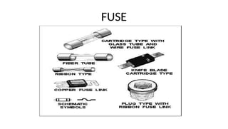
• Types offuse :-
I. Re-wirable type .
II. Cartridge type .
FUSE
11.
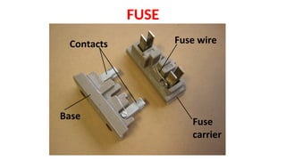
Re-wirable type fuse:-(Kit-kat fuse) .
The fuse element in this type of fuse consists of a wire which may be
replaced when necessary.
These fuses are simple in construction and the initial cost as well as the
renewal cost is very low.
The fuse elements used in this type are tinned copper wire, lead and tin
alloy.
Approximate size of fuse elements of tinned copper wire or aluminium wire
for use in semi-enclosed fuses .
FUSE
The fuseelement will melt after approximately 2 minutes when carrying a current
equal to twice the current rating.
However, the cut-off time factor varies in rewirable fuses due to;
I. The construction of the carrier .
II. The manner in which the fuse was in service.
III. The length of time the fuse was in service.
IV. Ambient temperature.
V. The amount of current etc.
FUSE
14.
• Disadvantages ofrewirable type fuse:
i. Deterioration of the fuse element by oxidation due to heating.
ii. Lack of discrimination.
iii. Effected by the fluctuation of the ambient temperature.
iv. Low speed operation .
v. External flash or arc on blowing.
vi. Poor rupturing capacity .
vii. Wrong rating possible by human error
FUSE
15.
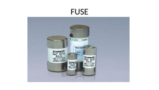
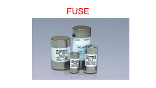
Cartridge fuses
o Cartridgefuses are developed to over come the disadvantages of rewirable fuses.
o As cartridge fuse elements are enclosed in an air tight chamber, deterioration dose
not take place.
o Further the rating of a cartridge fuse could be accurately determined from its
marking.
o How ever , the cost of replacement of cartridge fuses is more than that of rewirable
fuses .
FUSE
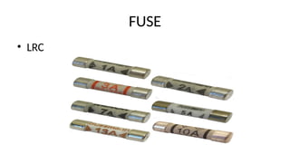
• Cartridge fusescan be grouped as those with a :
I. Low rupturing capacity.
II. High rupturing capacity.
FUSE
18.
FUSE
Rupturing capacityis the ability of a fuse to open the faulty circuit
without much arcing or damage to it self.
For domestic installations, low rupturing capacity fuses are used
whereas for power factory installations, and for installations
connected from high power sources, High rupturing
capacity(HRC).
19.
FUSE
• Low rupturingcapacity cartridge fuses can be further divided in-
to two types .
1. Ferrule- contact cartridge fuses.
2. Diazed screw-type cartridge fuses.
20.
FUSE
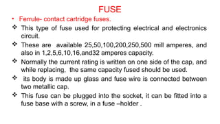
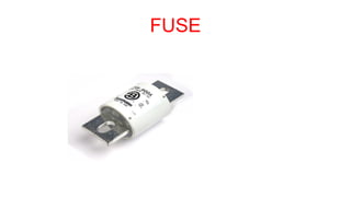
• Ferrule- contactcartridge fuses.
This type of fuse used for protecting electrical and electronics
circuit.
These are available 25,50,100,200,250,500 mill amperes, and
also in 1,2,5,6,10,16,and32 amperes capacity.
Normally the current rating is written on one side of the cap, and
while replacing, the same capacity fused should be used.
its body is made up glass and fuse wire is connected between
two metallic cap.
This fuse can be plugged into the socket, it can be fitted into a
fuse base with a screw, in a fuse –holder .
FUSE
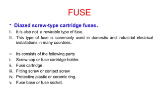
• Diazed screw-typecartridge fuses.
I. It is also not a rewirable type of fuse.
II. This type of fuse is commonly used in domestic and industrial electrical
installations in many countries.
o Its consists of the following parts
i. Screw cap or fuse cartridge-holder.
ii. Fuse cartridge .
iii. Fitting screw or contact screw
iv. Protective plastic or ceramic ring.
v. Fuse base or fuse socket.
FUSE
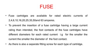
• Fuse cartridgesare available for rated electric currents of
2,4,6,10,16,20,25,35,50and 63 amperes.
• To prevent the insertion of a fuse cartridge having a large current
rating than intended, the foot contacts of the fuse cartridges have
different diameters for each rated current i.g for the smaller the
current the smaller the diameter of the foot contact.
• As there is also a separate fitting screw for each type of cartridge.
26.
FUSE
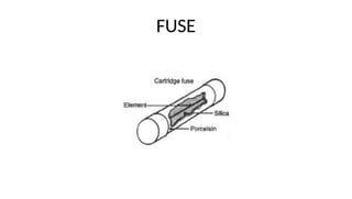
Construction of acartridges fuse:-
• The ceramic body of the cartridge with its foot and head
contacts.
• The two contacts are linked by a fuse wire which is embedded in
sand.
• Each cartridge has a break indicator which will be ejected from
the cartridge if the fuse wire burnt out.
• For easy identification of the fuse cartridges and the
corresponding fitting screws ,they are marked with various
colours.
27.
FUSE
• The partof cartridge fuse are:-
i. Head contact
ii. Break indicator
iii. Fuse wire
iv. Sand filling
v. Ceramic fuse body
vi. Foot contact.
FUSE
• Diazed typefuses are also available in two categories:-
a) Quick-response
b) Delayed- action type.
• The quick response type is used for heating circuits and normal
loads where as the delayed- action type is used for motor circuit
and highly inductive circuits.
FUSE
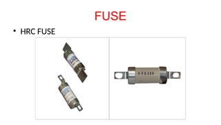
• High rupturingcapacity fuses(HRC) :-
o They are cylindrical in shape and are made of a ceramic body filled in with
a chemically treated filling powder or silica to quench the arcing quickly
without any fire hazard.
o Normally a silver alloy is used as the fusing element and when it melts due
to the excessive current, it combines with the surrounded sand/powder ,
and forms small globules without making an arc, spark or gas.
o HRC fuses can open a short-circuited circuit with in 0.013 second.

![COURSE OUTCOMES
CO 1 - Analyze electrical circuits using mesh analysis, nodal analysis and
network theorems. [A].
CO 2 - Examine the behavior of single-phase and three-phase AC circuits.
[AP].
CO 3 - Illustrate the operation and applications of various electrical
machines. [U].
CO 4 - Interpret the various wiring systems, ensuring adherence to Bureau
of Indian Standards (BIS) safety regulations. [U].
CO 5 - Investigate and design analog and digital electronic circuits. [AP].
2](https://image.slidesharecdn.com/4-251011045950-31e80bc8/85/Fuses-Earthing-IN-ELECTRICAL-ENGINEERING-2-320.jpg)