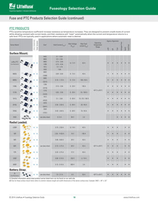
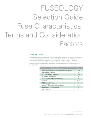
This document provides an overview of fuse characteristics, terms, considerations, and selection factors. It defines key fuse-related terms like current rating, breaking capacity, dimensions, and construction. It also covers selection factors like ambient temperature, pulses, and standards. The purpose is to help readers understand fuses and properly select the right fuse for their application. Selection involves considering characteristics like operating current, temperature, pulses and standards to avoid issues like nuisance opening.

![Fuseology Selection Guide
© 2015 Littelfuse • Fuseology Selection Guide www.littelfuse.com
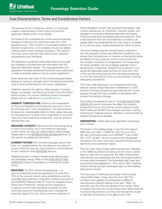
4. OVERLOAD CURRENT CONDITION: The current level
for which protection is required. Fault conditions may be
specified, either in terms of current or, in terms of both
current and maximum time the fault can be tolerated
before damage occurs. Time-current curves should be
consulted to try to match the fuse characteristic to the
circuit needs, while keeping in mind that the curves are
based on average data.
5. MAXIMUM FAULT CURRENT: The Interrupting Rating
of a fuse must meet or exceed the Maximum Fault Current
of the circuit.
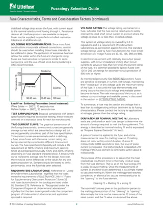
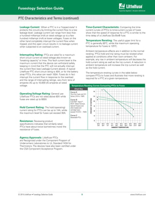
6. PULSES: The general term “pulses” is used in this
context to describe the broad category of wave shapes
referred to as “surge currents”, “start-up currents”, “inrush
currents”, and “transients”. Electrical pulse conditions can
vary considerably from one application to another. Different
fuse constructions may not react the same to a given
pulse condition. Electrical pulses produce thermal cycling
and possible mechanical fatigue that could affect the life
of the fuse. Initial or start-up pulses are normal for some
applications and require the characteristic of a Slo-Blo®
fuse. Slo-Blo®
fuses incorporate a thermal delay design
to enable them to survive normal start-up pulses and still
provide protection against prolonged overloads. The start-
up pulse should be defined and then compared to the time-
current curve and I2
t rating for the fuse. Application testing
is recommended to establish the ability of the fuse design
to withstand the pulse conditions.
Nominal melting I2
t is a measure of the energy required
to melt the fusing element and is expressed as “Ampere
Squared Seconds” (A2
Sec.). This nominal melting I2
t,
and the energy it represents (within a time duration of
8 milliseconds [0.008 second] or less and 1 millisecond
[0.001 second]or less for thin film fuses), is a value that is
constant for each different fusing element. Because every
fuse type and rating, as well as its corresponding part
number, has a different fusing element, it is necessary to
determine the I2
t for each. This I2
t value is a parameter of
the fuse itself and is controlled by the element material
and the configuration of the fuse element. In addition
to selecting fuses on the basis of “Normal Operating
Currents”, “Rerating”, and “Ambient Temperature” as
discussed earlier, it is also necessary to apply the I2
t
design approach. This nominal melting I2
t is not only a
constant value for each fuse element design, but it is also
independent of temperature and voltage. Most often, the
nominal melting I2
t method of fuse selection is applied to
those applications in which the fuse must sustain large
current pulses of a short duration. These high-energy
currents are common in many applications and are critical
to the design analysis.
The following example should assist in providing a better
understanding of the application of I2
t.
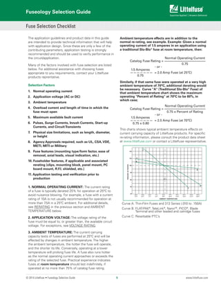
EXAMPLE: Select a 125V, very fast-acting PICO®
II fuse that
is capable of withstanding 100,000 pulses of current (I) of
the pulse waveform shown in Figure 1.
The normal operating current is 0.75 ampere at an ambient
temperature of 25ºC.
Step 1 — Refer to Chart 1 and select the appropriate
pulsewaveform, which is waveform (E) in this example.
Place the applicable value for peak pulse current (ip
) and
time (t) into the corresponding formula for waveshape (E),
and calculate the result, as shown:
1
I2
t = — (iP
) 2
t
5
1
= —×82
×.004 = 0.0512 A2
Sec.
5
This value is referred to as the “Pulse I2
t”.
Step 2 — Determine the required value of Nominal Melting
I2
t by referring to Chart 2. A figure of 22% is shown in
Chart II for 100,000 occurrences of the Pulse I2
t calculated
in Step 1. This Pulse I2
t is converted to its required value of
Nominal Melting I2
t as follows:
Nom. Melt I2
t = Pulse I2
t/.22
0.0512/.22 = 0.2327 A2
Sec.
Step 3 — Examine the I2
t rating data for the PICO®
II, 125V,
very fast-acting fuse. The part number 251001, 1 ampere
design is rated at 0.256 A2
Sec., which is the minimum
fuse rating that will accommodate the 0.2327 A2
Sec.
value calculated in Step 2. This 1 ampere fuse will also
accommodate the specified 0.75 ampere normal operating
current, when a 25% derating factor is applied to the 1
ampere rating, as previously described.
7. PHYSICAL SIZE LIMITATIONS: Please refer to the
product dimensions presented in current Littelfuse product
data sheets for specific information.
8. AGENCY APPROVALS: For background information
about common standards, please consult the STANDARDS
section of this guide or visit our Design Support web site
at www.littelfuse.com/design-support.html. For specific
agency approval information for each Littelfuse product,
please refer to the data sheets within this catalog and
information presented on www.littelfuse.com. As agency
approvals and standards may change, please rely on the
information presented on www.littelfuse.com as current
information.
9. FUSE FEATURES: Please consult the specific product
features presented within this catalog and on our web
site at www.littelfuse.com. For additional information and
support contact your Littelfuse product representative.
Fuse Selection Checklist (continued)
6](https://image.slidesharecdn.com/littelfusefuseologyselectionguide-180928224245/85/Littelfuse-fuseology-selection_guide-pdf-7-320.jpg)
![© 2014 Littelfuse • Fuseology Selection Guide www.littelfuse.com
Fuseology Selection Guide
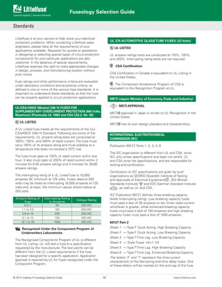
UL/CSA/ANCE (Mexico) 248-14 vs. IEC 60127 Part 2 FUSE
OPENINGTIMES vs. METI/MITI
Percent of
Rating
UL & CSA
STD 248-14
IEC TYPE F
Sheet 1 (*)
IEC TYPE F
Sheet 2 (*)
IEC TYPE T
Sheet 3 (*)
IEC TYPE T
Sheet 5 (*)
METI/MITI
100 4Hr.Min. — — — —
130 — — — — — 1Hr.Min.
135
60 Minutes
Max.
— — — —
150 —
60 Minutes
Min.
60 Minutes
Min.
60 Minutes
Min.
60 Minutes
Min.
160 — — — — — 1Hr.Max.
200
2 Minutes
Max.
— — — —
2 Minutes
Max.
210 —
30 Minutes
Max.
30 Minutes
Max.
2 Minutes
Max.
30 Minutes
Max.
(*) Note: The IEC Specification is written up to
10.0A. Any components above these ratings are
not recognized by the IEC (although the fuses
may have similar opening characteristics).
IEC also has opening time requirements at 275%, 400%
and 1000%; however, the chart is used to show that
fuses with the same ampere rating made to different
specifications are not interchangeable. According to the
IEC 60127 Standard, a one ampere-rated fuse can be
operated at one ampere. A one ampere-rated fuse made to
UL/CSA/ANCE 248-14 should not be operated at more than
.75 ampere (25% derated — See RERATING section).
METI B does not differentiate between fast acting and time
delay characteristics.
Publication IEC 60127-4 (Universal Modular Fuse-Links
[UMF])
This part of IEC 60127-4 covers both PCB through-hole
and surface mount fuses. This standard covers fuses rated
32, 63, 125, and 250 volts. This standard will be accepted
by UL/CSA making it the first global fuse standard. This
specification uses different fusing gates than IEC 60127-2;
the gates used here are 125%, 200%, and 1000%.
The fuses must not open in less than one hour at 125%
of rated current and open within two minutes at 200% of
rated current. The 1000% overload is used to determine
the fuse characteristic. The opening time for each rating is
listed below.
Type FF : Less than 0.001 sec.
Type F : From 0.001 - 0.01 sec.
Type T : From 0.01 - 0.1 sec.
Type TT : From 0.1 - 1.00 sec.
These characteristics correlate to the terminology used in
IEC 60127-1.
Breaking capacity (interrupting rating) varies based on
voltage rating. Parts rated at 32 & 63 volts must pass a
test of 35 amperes or ten times rated current, whichever
is greater. Parts rated at 125 volts must pass a test of 50
amperes or ten times rated current, whichever is greater.
Parts rated at 250 volts are further defined as either low,
intermediate or high breaking. The low breaking capacity
fuses must pass a test of 100 amperes rated current, while
intermediate breaking capacity fuses must pass a test of
500 amperes and high breaking capacity fuses must pass a
test of 1500 amperes.
MILITARY/FEDERAL STANDARDS
MIL-PRF-15160 and MIL-PRF-23419
These specifications govern the construction and
performance of fuses suitable primarily for military
electronic applications.
MIL-PRF-19207
This specification governs the construction and
performance of fuseholders suitable for military
applications.
DSSC Drawing #87108
This drawing governs the construction and performance
of .177” × .570” (2AG size) cartridge fuses and axial lead
versions suitable for military applications. DSSC #87108
designation is included in the fuse end cap marking.
Standards (continued)
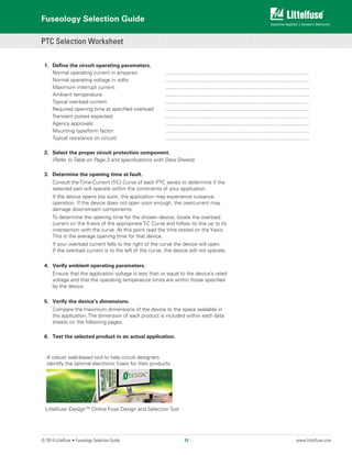
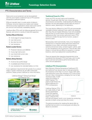
A robust web-based tool to help circuit designers
identify the optimal electronic fuses for their products.
To use the Littelfuse iDesign tool, simply register to
create a free online account at the iDesign Login.
13](https://image.slidesharecdn.com/littelfusefuseologyselectionguide-180928224245/85/Littelfuse-fuseology-selection_guide-pdf-14-320.jpg)