Downloaded 16 times
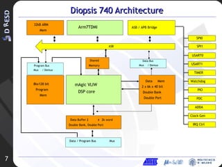
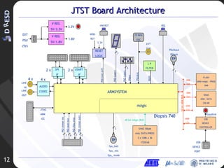
![JTST Board Architecture JTST: Jig Test for D740 Memories: SSRAM toward mAgic, FLASH and SRAM toward ARM 4 Stereo Audio 20 bit CODECs Serial I/O: 1 USB 2.0 Full (12 Mbps) 2 RS232/LVTTL serial ports 2 SPI serial I/O lines Reset Logic (Power ON, Push Button, WDG) IO connectors (USART, SPI, USB, PIO, AUDIO) 25 MHz oscillator Configuration DIP SWITCH & Status 7-segment Display Voltage Regulators 5V/3.3V & 5V/1.8V CLK DIV 3.3V LED IRQ BUTTON PIO CONN SRAM ARM DATA L 128kx8 SRAM ARM DATA H 128kx8 FLASH ARM PRG 1Mx16 SSRAM MAGIC DATA L 128kx36 EXTCLK CONN DIP SWITCH SPI-0 CONN M-ICE JTAG CONN Diopsis 740 PIO USARTs RST XMA XMD[15:0] CLKs CNTRLs SPIs ADDA ARMD PLL ICE ARMC ARMA XMD[55:40] XMD[31:16] XMD[71:56] XMD[39:32] XMD[79:72] SSRAM MAGIC DATA H 128kx36 SSRAM MAGIC DATA E 128kx36 USB CNTRL USB CONN EXT PSU CONN CODEC CODEC CODEC CODEC CLK DIV 25 MHz OSC RS 232 BUFF RS 232 BUFF USART 0 CONN USART 1 CONN 7-SEG DISPLAY GND GND RESISTOR NETWORK RESISTOR NETWORK 6 MHz D-9 RS232 CONN D-9 RS232 CONN RST BUTTON VREG 5-1.8 SPI-1 CONN VREG 5-3.3 USB LED LED BUFF RST BUFF ADDA BUFF POW-ON RST AUDIO OUT CONN AUDIO IN CONN AUDIO OUT CONN AUDIO IN CONN AUDIO OUT CONN AUDIO IN CONN AUDIO OUT CONN AUDIO IN CONN RESISTOR NETWORK RESISTOR NETWORK RESISTOR NETWORK RESISTOR NETWORK RESISTOR NETWORK JP8 JP9 JP5 JP4 JP11 JP7 JP2 JP3 JP6 JP10 JP1 TP5 TP2 TP1 TP4 TP3 TP7 TP8 TP6 TP9 TP10 TP11](https://image.slidesharecdn.com/3ddresd-asida1953/85/3D-DRESD-ASIDA-10-320.jpg)
![JTST Board Architecture CLK DIV 3.3V LED IRQ BUTTON PIO CONN SRAM ARM DATA L 128kx8 SRAM ARM DATA H 128kx8 FLASH ARM PRG 1Mx16 SSRAM MAGIC DATA L 128kx36 EXTCLK CONN DIP SWITCH SPI-0 CONN M-ICE JTAG CONN Diopsis 740 PIO USARTs RST XMA XMD[15:0] CLKs CNTRLs SPIs ADDA ARMD PLL ICE ARMC ARMA XMD[55:40] XMD[31:16] XMD[71:56] XMD[39:32] XMD[79:72] SSRAM MAGIC DATA H 128kx36 SSRAM MAGIC DATA E 128kx36 USB CNTRL USB CONN EXT PSU CONN CODEC CODEC CODEC CODEC CLK DIV 25 MHz OSC RS 232 BUFF RS 232 BUFF USART 0 CONN USART 1 CONN 7-SEG DISPLAY GND GND RESISTOR NETWORK RESISTOR NETWORK 6 MHz D-9 RS232 CONN D-9 RS232 CONN RST BUTTON VREG 5-1.8 SPI-1 CONN VREG 5-3.3 USB LED LED BUFF RST BUFF ADDA BUFF POW-ON RST AUDIO OUT CONN AUDIO IN CONN AUDIO OUT CONN AUDIO IN CONN AUDIO OUT CONN AUDIO IN CONN AUDIO OUT CONN AUDIO IN CONN RESISTOR NETWORK RESISTOR NETWORK RESISTOR NETWORK RESISTOR NETWORK RESISTOR NETWORK JP8 JP9 JP5 JP4 JP11 JP7 JP2 JP3 JP6 JP10 JP1 TP5 TP2 TP1 TP4 TP3 TP7 TP8 TP6 TP9 TP10 TP11](https://image.slidesharecdn.com/3ddresd-asida1953/85/3D-DRESD-ASIDA-11-320.jpg)
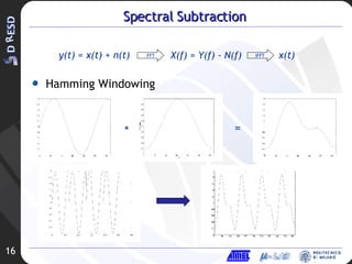
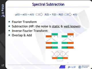
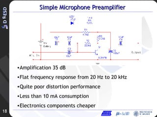
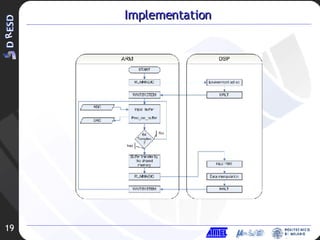
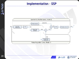
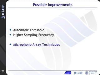
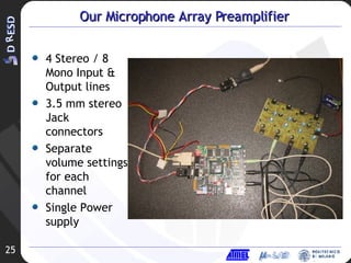

The document discusses audio signal improvement techniques for a D740 architecture, including: 1. Spectral subtraction is proposed to remove background noise from audio signals. 2. A simple microphone preamplifier design is presented that provides amplification but has limitations in distortion performance and power consumption. 3. Future work is proposed combining spectral subtraction with direction of arrival techniques using a microphone array to further improve noise reduction.


