Download to read offline
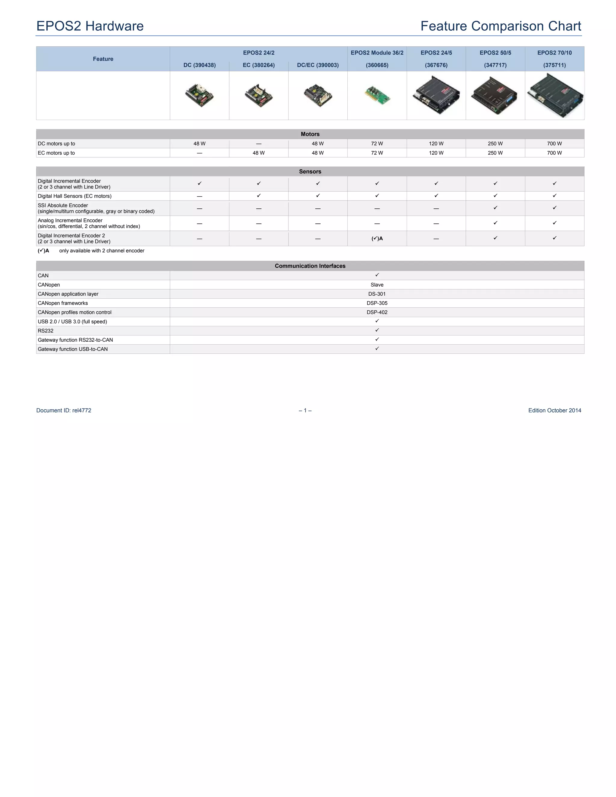
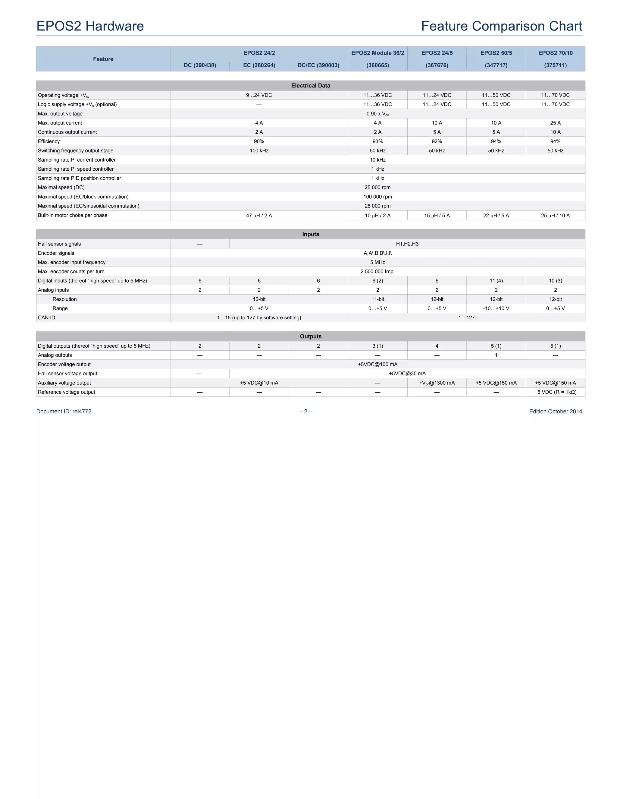
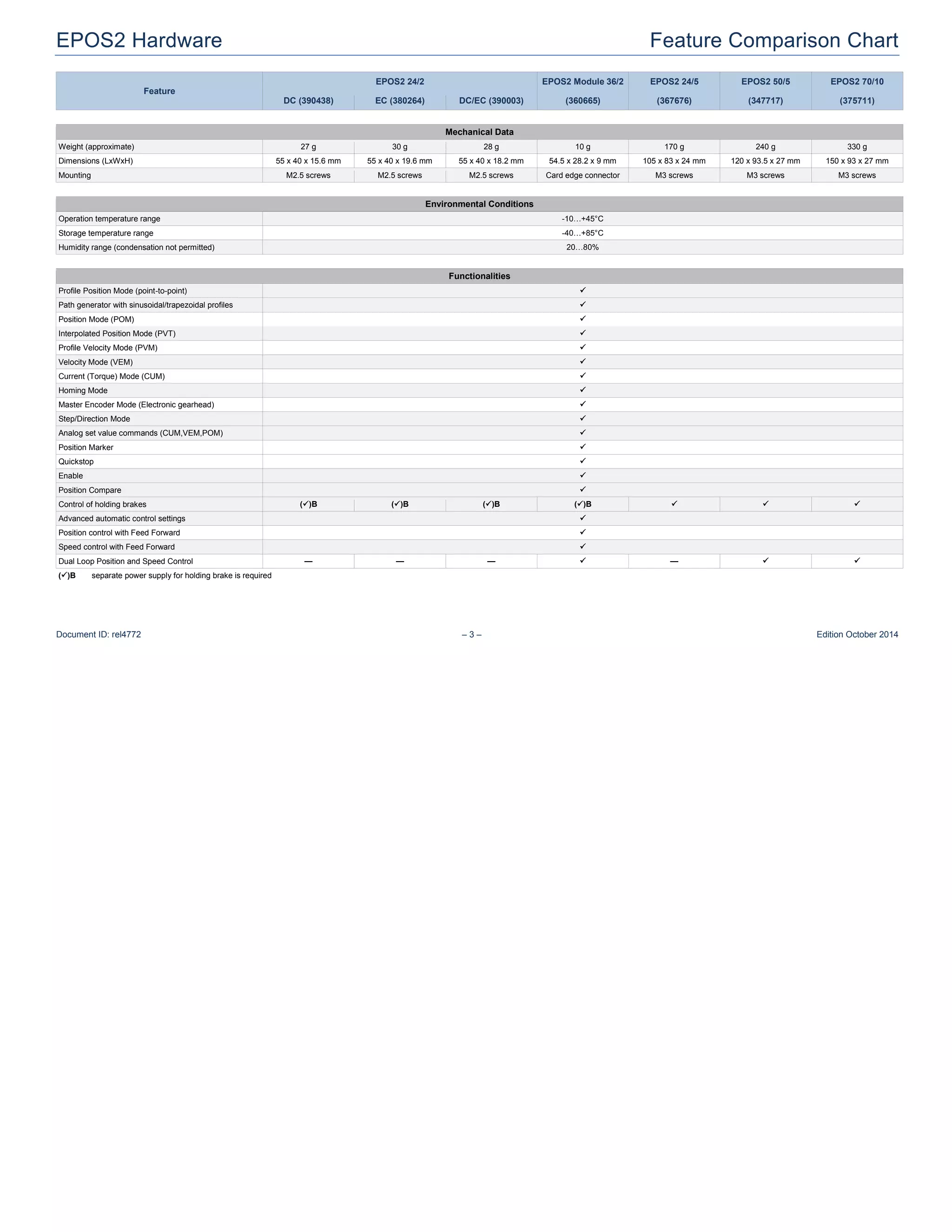
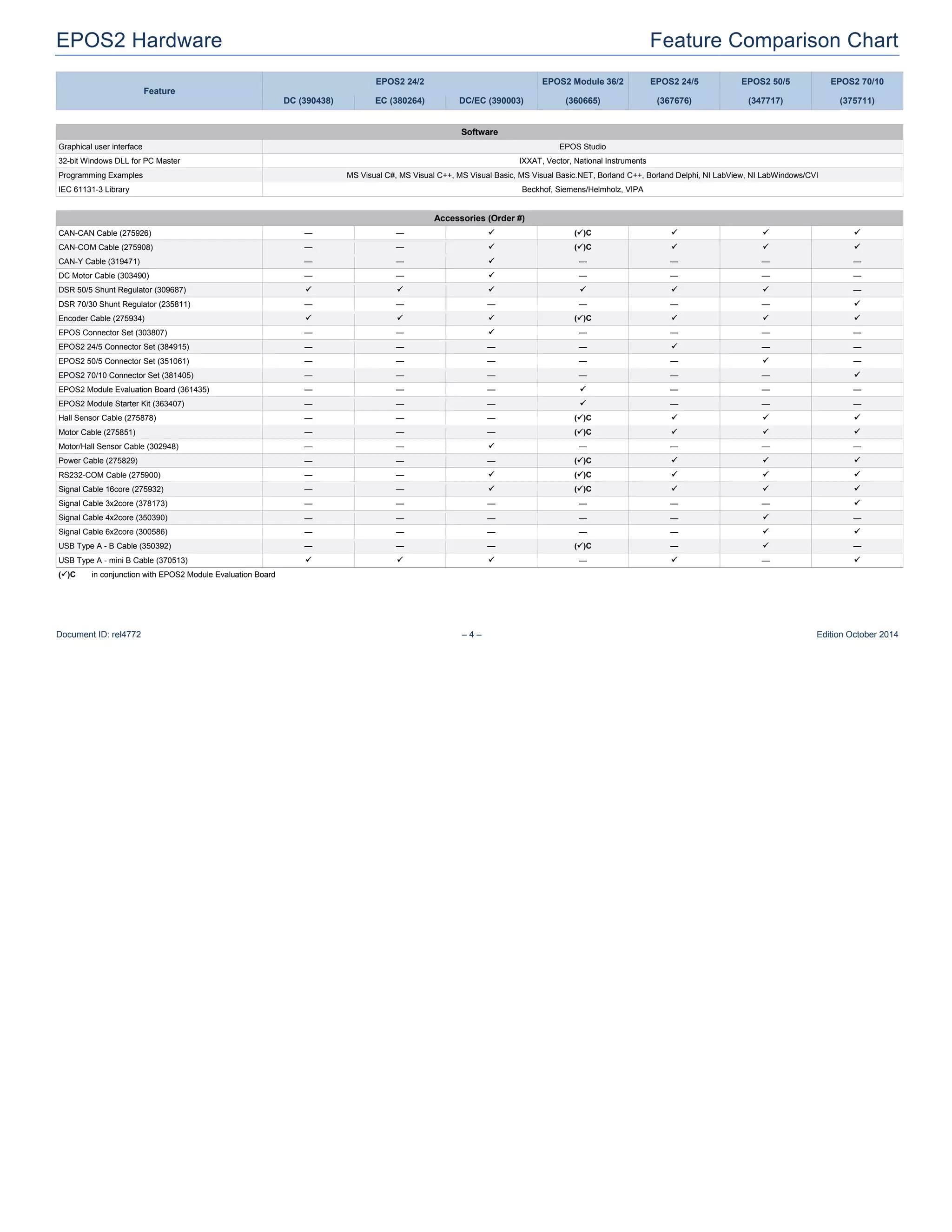

This document provides specifications for several EPOS2 motor controllers including the EPOS2 24/2, EPOS2 Module 36/2, EPOS2 24/5, EPOS2 50/5, and EPOS2 70/10. It details their electrical features such as voltage, current capacity, and efficiency. It also outlines their mechanical features, environmental specifications, communication interfaces including CAN and USB, and motor control functionalities such as position and velocity modes. The document provides ordering information for accessories like cables and evaluation boards for each controller.


![Coded Agents – with UiPath SDK + LangGraph [Virtual Hands-on Workshop]](https://cdn.slidesharecdn.com/ss_thumbnails/codedagentsdeck-251215155422-5497c599-thumbnail.jpg?width=640&height=640&fit=bounds)


![Vibe Coding vs. Spec-Driven Development [Free Meetup]](https://cdn.slidesharecdn.com/ss_thumbnails/vibecodingvsspecdrivendevelopment-251209105622-43f455e7-thumbnail.jpg?width=640&height=640&fit=bounds)