Downloaded 737 times


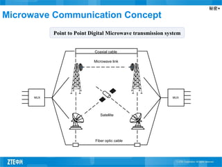
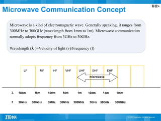
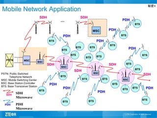
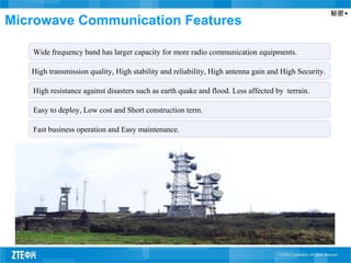
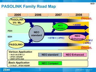
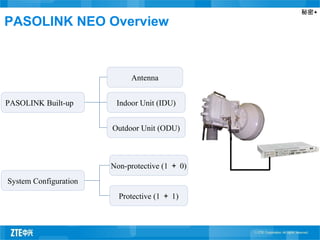
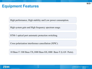
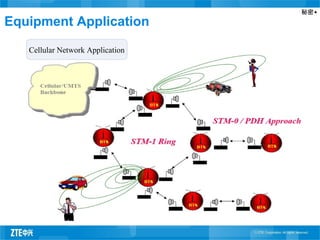
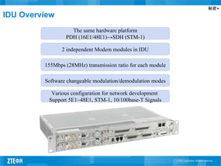
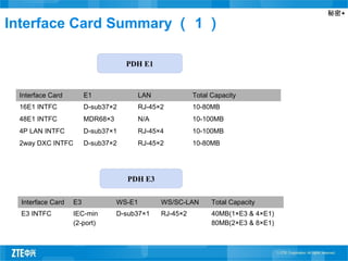
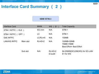
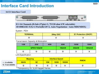
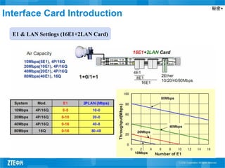
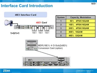
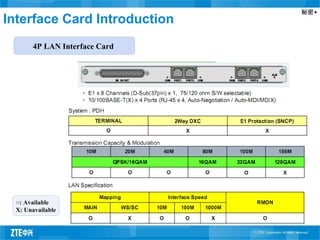

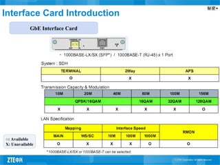
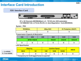
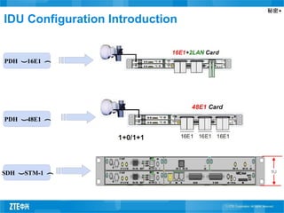
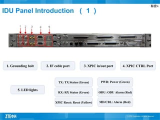
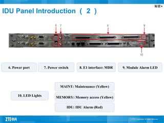
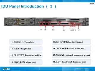
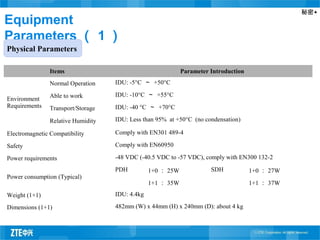
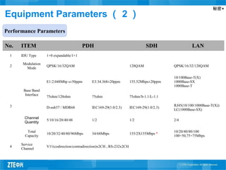
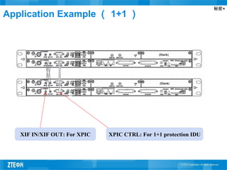
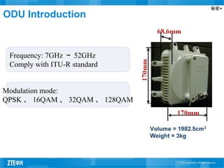
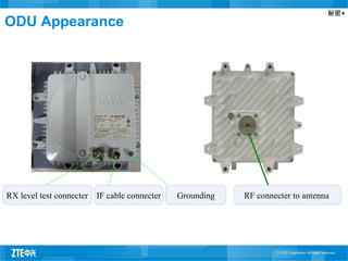
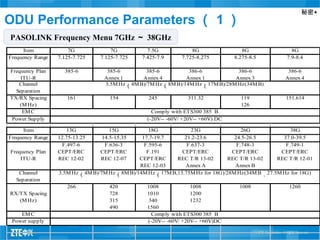
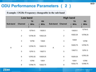
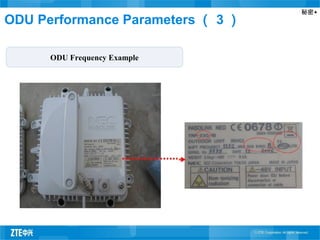
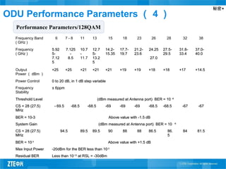

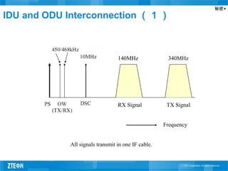
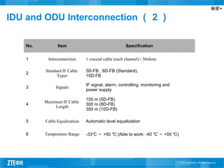
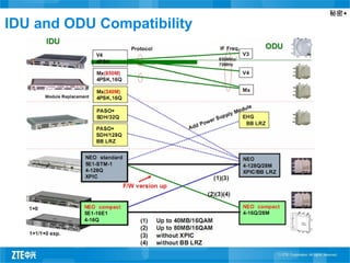


The document introduces the NEC NEO Microwave equipment, including PASOLINK NEO. It discusses microwave communication concepts and applications in mobile networks. It provides an overview of PASOLINK equipment, including the indoor and outdoor units. Key specifications of the indoor unit such as interface cards and configuration are described. The document also covers performance parameters of the outdoor unit such as modulation modes and operating frequencies.


