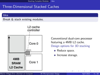
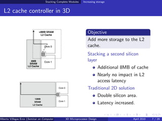
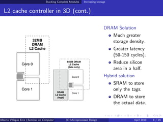
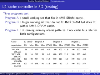
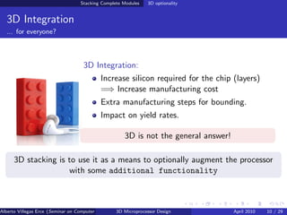
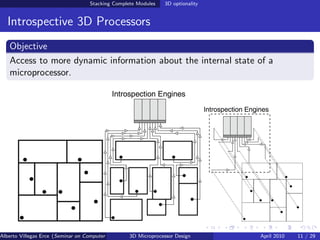
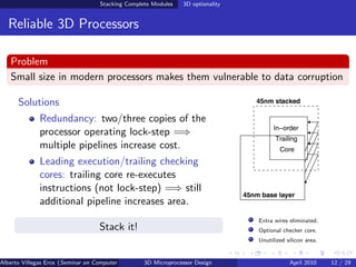
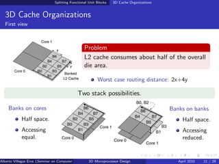
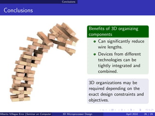
The document discusses stacking complete modules in 3D microprocessor design at different granularities. It proposes stacking an additional silicon layer containing 8MB of L2 cache to increase storage with little impact on access latency compared to traditional 2D designs. Testing shows this benefits workloads with working sets that exceed the 4MB L2 cache. The document also discusses optionally using 3D stacking to provide additional functionality like accessing internal processor state or adding reliability through redundant execution.
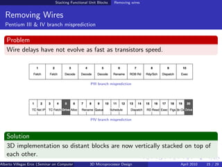

![Splitting Functional Unit Blocks 3D Adders
3D Adders
Classic Look-ahead Carry Adder
Look-ahead Carry Adder
n = 16-bits
Critical path along bit[0]-bit[n-1]
Several ways to split the adder
Based on inputs By significance
x bottom layer; least significant bits
y top layer. bottom layer;
most significant top
1st lvl of propagate layer.
layer splitted.
TSV between root
Half wire length. nodes.
Alberto Villegas Erce (Seminar on Computer Systems Turku University ) Design
3D Microprocessor April 2010 24 / 29](https://image.slidesharecdn.com/charla-110403165838-phpapp01/85/3D-Microprocessor-Design-Stacking-at-different-granularities-24-320.jpg)


![[IJET-V1I6P5] Authors: Tawde Priyanka, Londhe Archana, Nazirkar Sandhya, Khat...](https://cdn.slidesharecdn.com/ss_thumbnails/ijet-v1i6p5-151213072519-thumbnail.jpg?width=640&height=640&fit=bounds)