Downloaded 181 times
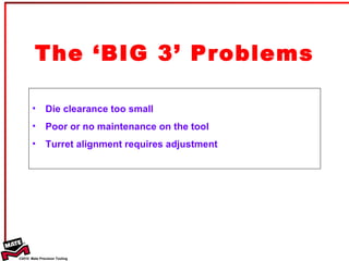
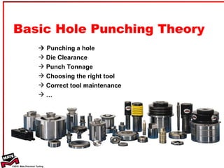
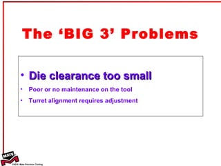
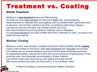
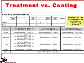
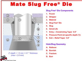
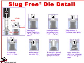

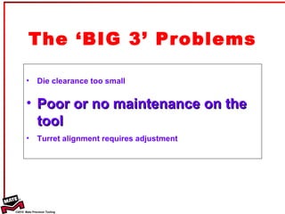
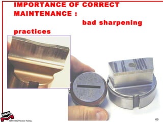
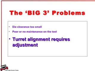

The document provides information on basic punching theory and techniques. It discusses the three main problems in punching as die clearance being too small, poor tool maintenance, and misaligned turrets. It also covers topics such as die clearance, tonnage calculation, punch types, tool coatings and treatments, punching thick and thin materials, and the importance of tool maintenance.


