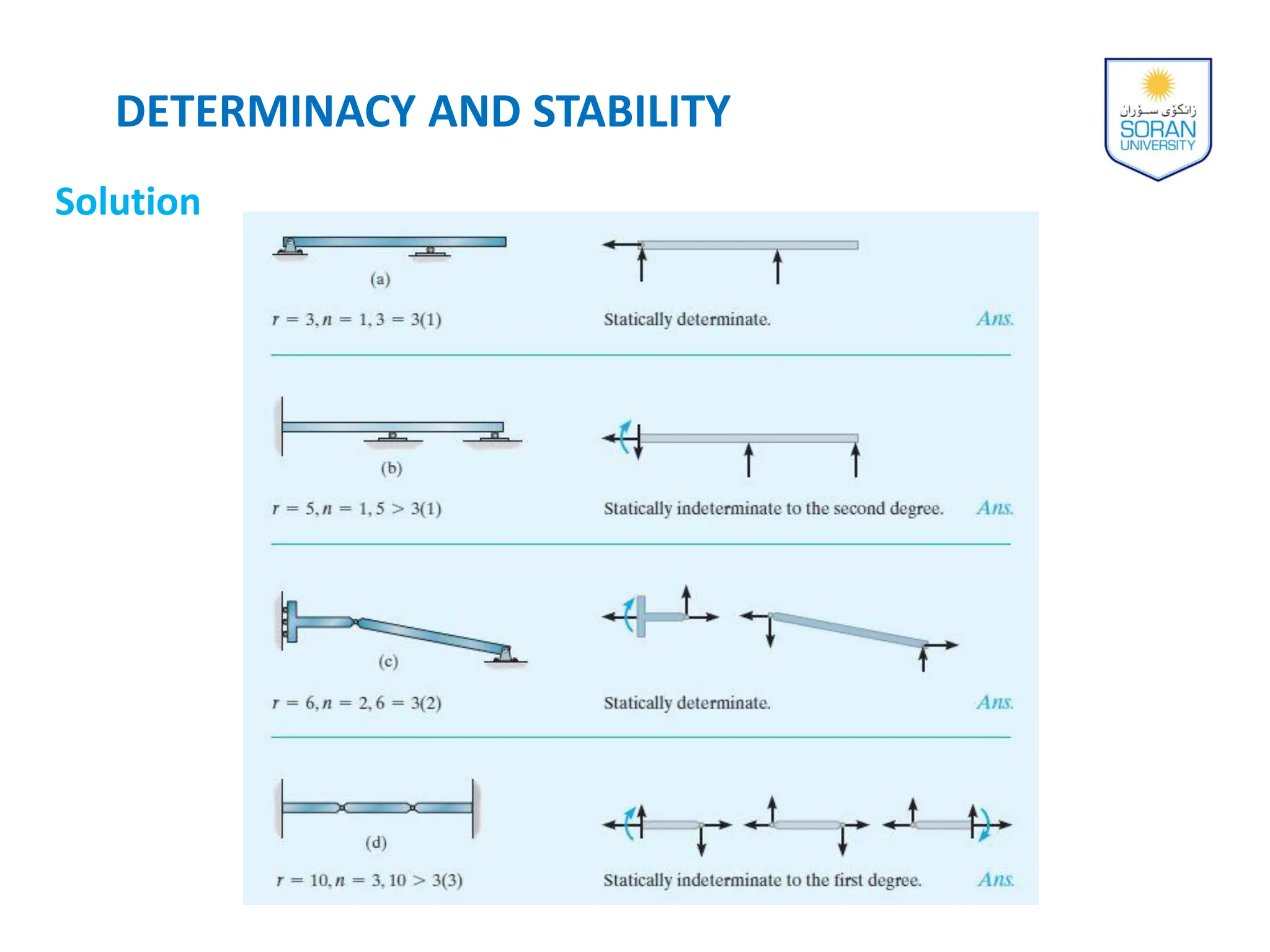
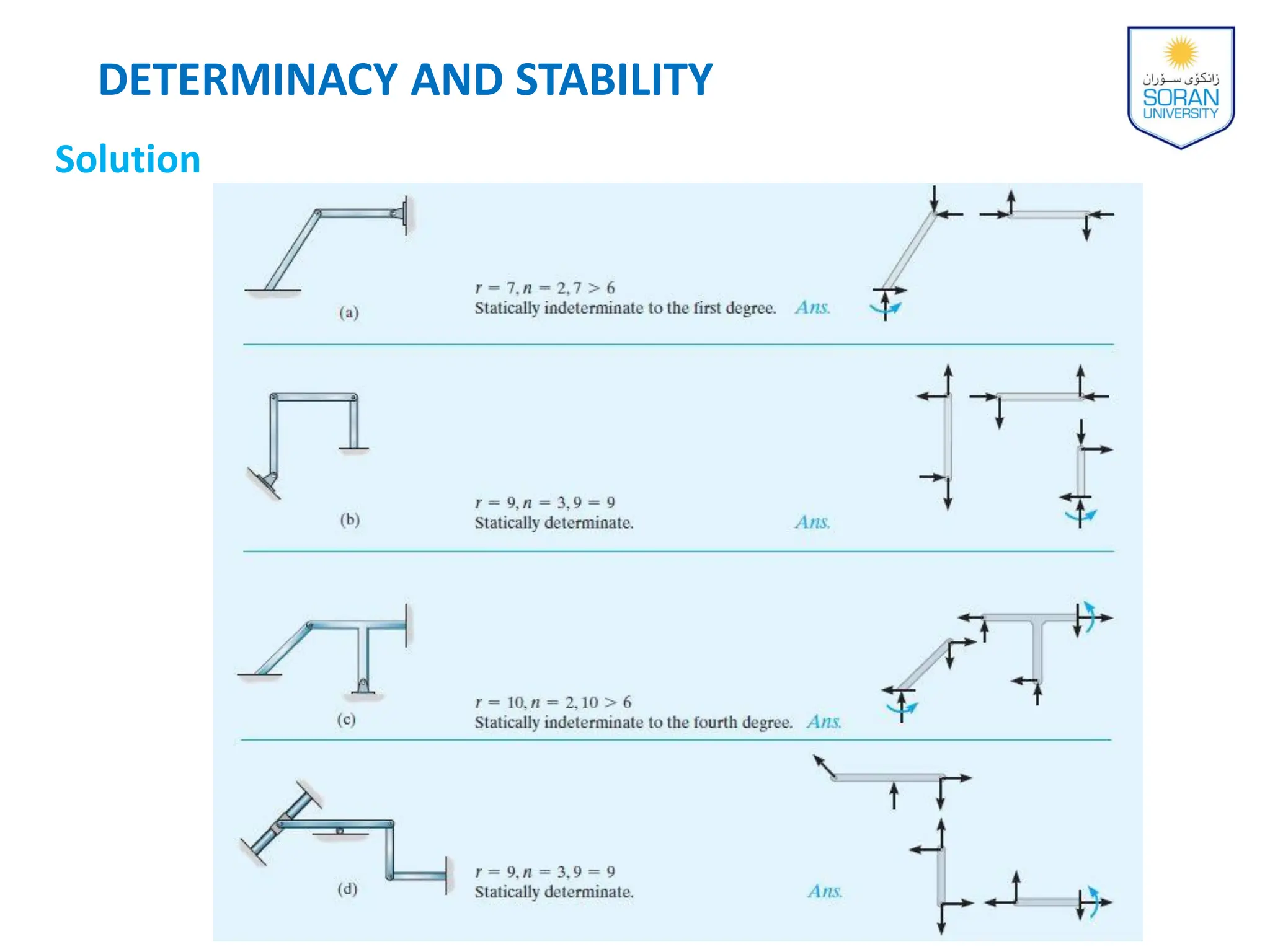
STRUCTURAL ANALYSIS
(Determinate)
Soran University
Faculty of Engineering
Civil Engineering Department
Yousif J. Bas
(2023-2024)
CHAPTER 2
Analysis of Statically
Determinate
Structures
Analysis of Statically
Determinate Structures
CHAPTER OBJECTIVES
 To show how structures can be idealized and modeled for
analysis.
 To define structural stability.
 To show how to analyze statically determinate, planar,
pin-connected structures.
R. C. Hibbeler, Structural Analysis, 10th Edition, 2017 (Yousif J. Bas)
Chapter Outline
 Idealized Structure
 Load Path
 Principle of Superposition
 Equations of Equilibrium
 Determinacy and Stability
 Application of the Equations of Equilibrium
Idealized Structure
 To develop the ability to model or idealize a structure so that
the structural engineer can perform a practical force analysis
of the members
 Support Connections
 Pin connection (allows some freedom for slight rotation)
 Roller support (allows some freedom for slight rotation)
 Fixed joint (allows no relative rotation)
Idealized Structure
Idealized Structure
Idealized Structure
Idealized Structure
 Support Connections
 In reality, all connections exhibit some stiffness toward joint
rotations owing to friction & material behavior
 If 𝐾 = 0, the joint is pin, and if 𝐾 = ∞ , the joint is fixed
 When selecting the model for each support, the engineer
must be aware of how the assumptions will affect the actual
performance
 The analysis of the loadings should give results that closely
approximate the actual loadings
Idealized Structure
 Support Connections
Idealized Structure
 Idealized Structure
 Consider the jib crane & trolley, we neglect the thickness of the
2 main member & will assume that the joint at B is fabricated to
be rigid
 The support at A can be modeled as a fixed support
 Idealized Structure
 Consider the framing used to support a typical floor slab in a
building
 The slab is supported by floor joists located at even intervals
 These are in turn supported by 2 side girders AB & CD
 For analysis, it is reasonable to assume that the joints are pin
and/or roller connected to girders & the girders are pin and/or
roller connected to columns
 Tributary Loadings
 There are 2 ways in which the load on surfaces is
transmitted to various structural elements
 1-way system
 2-way system
Idealized Structure
 Tributary Loadings
 1-way system
According to the American Concrete Institute, ACI 318 code, with 𝐿2
≥ 𝐿1 if the span ratio (𝐿2/𝐿1) > 2, the slab will then behave as a
one-way slab, since then the beams AB, CD, and EF provide the
greater capacity to carry “most” of the load.
Idealized Structure
 Tributary Loadings
 2-way system
If 1 ≤ (𝐿2/𝐿1) ≤ 2, then the load is assumed to be transferred to
the supporting members in two directions. When this is the case the
slab is referred to as a two-way slab.
Idealized Structure
 Tributary Loadings
 2-way system
Idealized Structure
Example
The floor of a classroom is to be supported by the bar joists as
shown. Each joist is 4.5 m long and they are spaced 0.75 m on
centers. The floor itself is to be made from lightweight concrete that
is 100 mm thick. Neglect the weight of the joists and the corrugated
metal deck, and determine the load that acts along each joist.
Idealized Structure
Solution
Dead load, weight of concrete slab
=(100)(0.015)= 1.50 kN/m2
Live load =1.92 kN/m2
Total load= 1.50 + 1.92= 3.42 kN/m2
𝐿1 = 0.75m, 𝐿2 = 4.5m
𝐿2/𝐿1 > 2 → one-way slab
Therefore the uniform load along
its length is:
w= 3.42kN/m2 (0.75m) 2.565 kN/m
Idealized Structure
 The various elements that make up a structure should be designed
in such a way that they transmit the primary load acting on the
structure to its foundation in the most efficient way possible.
 As a first step in any design or analysis, it is very important to
understand how the loads are transmitted through the structure if
damage or collapse is to be avoided. This description is called a
load path.
LOAD PATH
 the load acting on the floor of the building is transmitted from the
slab to the floor joists, then to the spandrel and interior girder,
and finally to the columns and foundation footings.
LOAD PATH
 The total displacement or the internal loadings at a point in a
structure subjected to several external loadings can be
determined by adding together the displacements or internal
loadings caused by each of the external loads acting separately
 Two requirements must be imposed for the principle of
superposition to apply:
1. The material must behave in a linear elastic manner, so that
Hooke’s law is valid.
2. The geometry of the structure must not undergo significant
change when the loads applied, i.e., small displacement theory
applies.
PRINCIPLE OF SUPERPOSITION
 For equilibrium:
EQUATIONS OF EQUILIBRIUM
∑𝐹𝑥= 0 ∑𝐹𝑦= 0 ∑𝐹𝑧= 0
∑𝑀𝑥= 0 ∑𝑀𝑦= 0 ∑𝑀𝑧= 0
∑𝐹𝑥= 0
∑𝐹𝑦= 0
∑𝑀𝑂= 0
 For most structures, it can be reduced to:
 Determinacy
 Equilibrium equations provide both the necessary and
sufficient conditions for equilibrium
 When all the forces on a stable structure can be determined
strictly from these equations
 No. of unknown forces > equilibrium equation = statically
indeterminate
 This can be determined using free body diagrams
DETERMINACY AND STABILITY
 Determinacy
 For a coplanar structure
DETERMINACY AND STABILITY
 The additional equations needed to solve for the unknown
equations are obtained as compatibility equations
DETERMINACY AND STABILITY
Example
Classify each of the beams as statically determinate or statically
indeterminate. If statically indeterminate, report the number of
degrees of indeterminacy. The beams are subjected to external
loadings that are assumed to be known and can act anywhere on the
beams.
DETERMINACY AND STABILITY
Solution
DETERMINACY AND STABILITY
Example
Classify each of the pin-connected structures as statically
determinate or statically indeterminate. If statically indeterminate,
report the number of degrees of indeterminacy. The structures are
subjected to arbitrary external loadings that are assumed to be
known and can act anywhere on the structures.
DETERMINACY AND STABILITY
Solution
 Stability
 To ensure equilibrium of a structure or its members:
1. Must satisfy equations of equilibrium
2. Members must be properly held or constrained by their
supports
DETERMINACY AND STABILITY
 Partial constraints
 Fewer reactive forces than
equations of equilibrium
 will not be satisfied
 Member will be unstable
DETERMINACY AND STABILITY
∑𝐹𝑥= 0
 Improper Constraints
 In some cases, unknown forces may equal equations of
equilibrium in number
 However, instability or movement of structure could still
occur if support reactions are concurrent at a point
DETERMINACY AND STABILITY
 Improper Constraints
 Rotation about point O will take place
 Similarly instability can occur if all reactive forces are parallel
DETERMINACY AND STABILITY
Example
Classify each of the structures as stable or unstable. The structures
are subjected to arbitrary external loads that are assumed to be
known.
DETERMINACY AND STABILITY
Solution
DETERMINACY AND STABILITY
Solution
Example
Determine the reactions on the beam shown bellow.
Solution
Example
Determine the reactions on the beam shown bellow.
Solution
Example
Determine the horizontal and vertical components of
reaction at the pins A, B, and C of the two-member
frame shown bellow.
Solution
Example
The side of the building is subjected to a wind loading that
creates a uniform normal pressure of 15 kPa on the windward
side and a suction pressure of 5 kPa on the leeward side.
Determine the horizontal and vertical components of reaction at
the pin connections A, B, and C of the supporting gable arch.
Solution
Solution

2-Analysis of Statically Determinate Structures.pdf

  • 1.
    STRUCTURAL ANALYSIS (Determinate) Soran University Facultyof Engineering Civil Engineering Department Yousif J. Bas (2023-2024)
  • 2.
    CHAPTER 2 Analysis ofStatically Determinate Structures
  • 3.
    Analysis of Statically DeterminateStructures CHAPTER OBJECTIVES  To show how structures can be idealized and modeled for analysis.  To define structural stability.  To show how to analyze statically determinate, planar, pin-connected structures. R. C. Hibbeler, Structural Analysis, 10th Edition, 2017 (Yousif J. Bas)
  • 4.
    Chapter Outline  IdealizedStructure  Load Path  Principle of Superposition  Equations of Equilibrium  Determinacy and Stability  Application of the Equations of Equilibrium
  • 5.
    Idealized Structure  Todevelop the ability to model or idealize a structure so that the structural engineer can perform a practical force analysis of the members  Support Connections  Pin connection (allows some freedom for slight rotation)  Roller support (allows some freedom for slight rotation)  Fixed joint (allows no relative rotation)
  • 6.
  • 7.
  • 8.
  • 9.
    Idealized Structure  SupportConnections  In reality, all connections exhibit some stiffness toward joint rotations owing to friction & material behavior  If 𝐾 = 0, the joint is pin, and if 𝐾 = ∞ , the joint is fixed  When selecting the model for each support, the engineer must be aware of how the assumptions will affect the actual performance  The analysis of the loadings should give results that closely approximate the actual loadings
  • 10.
  • 11.
    Idealized Structure  IdealizedStructure  Consider the jib crane & trolley, we neglect the thickness of the 2 main member & will assume that the joint at B is fabricated to be rigid  The support at A can be modeled as a fixed support
  • 12.
     Idealized Structure Consider the framing used to support a typical floor slab in a building  The slab is supported by floor joists located at even intervals  These are in turn supported by 2 side girders AB & CD  For analysis, it is reasonable to assume that the joints are pin and/or roller connected to girders & the girders are pin and/or roller connected to columns
  • 13.
     Tributary Loadings There are 2 ways in which the load on surfaces is transmitted to various structural elements  1-way system  2-way system Idealized Structure
  • 14.
     Tributary Loadings 1-way system According to the American Concrete Institute, ACI 318 code, with 𝐿2 ≥ 𝐿1 if the span ratio (𝐿2/𝐿1) > 2, the slab will then behave as a one-way slab, since then the beams AB, CD, and EF provide the greater capacity to carry “most” of the load. Idealized Structure
  • 15.
     Tributary Loadings 2-way system If 1 ≤ (𝐿2/𝐿1) ≤ 2, then the load is assumed to be transferred to the supporting members in two directions. When this is the case the slab is referred to as a two-way slab. Idealized Structure
  • 16.
     Tributary Loadings 2-way system Idealized Structure
  • 17.
    Example The floor ofa classroom is to be supported by the bar joists as shown. Each joist is 4.5 m long and they are spaced 0.75 m on centers. The floor itself is to be made from lightweight concrete that is 100 mm thick. Neglect the weight of the joists and the corrugated metal deck, and determine the load that acts along each joist. Idealized Structure
  • 18.
    Solution Dead load, weightof concrete slab =(100)(0.015)= 1.50 kN/m2 Live load =1.92 kN/m2 Total load= 1.50 + 1.92= 3.42 kN/m2 𝐿1 = 0.75m, 𝐿2 = 4.5m 𝐿2/𝐿1 > 2 → one-way slab Therefore the uniform load along its length is: w= 3.42kN/m2 (0.75m) 2.565 kN/m Idealized Structure
  • 19.
     The variouselements that make up a structure should be designed in such a way that they transmit the primary load acting on the structure to its foundation in the most efficient way possible.  As a first step in any design or analysis, it is very important to understand how the loads are transmitted through the structure if damage or collapse is to be avoided. This description is called a load path. LOAD PATH
  • 20.
     the loadacting on the floor of the building is transmitted from the slab to the floor joists, then to the spandrel and interior girder, and finally to the columns and foundation footings. LOAD PATH
  • 21.
     The totaldisplacement or the internal loadings at a point in a structure subjected to several external loadings can be determined by adding together the displacements or internal loadings caused by each of the external loads acting separately  Two requirements must be imposed for the principle of superposition to apply: 1. The material must behave in a linear elastic manner, so that Hooke’s law is valid. 2. The geometry of the structure must not undergo significant change when the loads applied, i.e., small displacement theory applies. PRINCIPLE OF SUPERPOSITION
  • 22.
     For equilibrium: EQUATIONSOF EQUILIBRIUM ∑𝐹𝑥= 0 ∑𝐹𝑦= 0 ∑𝐹𝑧= 0 ∑𝑀𝑥= 0 ∑𝑀𝑦= 0 ∑𝑀𝑧= 0 ∑𝐹𝑥= 0 ∑𝐹𝑦= 0 ∑𝑀𝑂= 0  For most structures, it can be reduced to:
  • 23.
     Determinacy  Equilibriumequations provide both the necessary and sufficient conditions for equilibrium  When all the forces on a stable structure can be determined strictly from these equations  No. of unknown forces > equilibrium equation = statically indeterminate  This can be determined using free body diagrams DETERMINACY AND STABILITY
  • 24.
     Determinacy  Fora coplanar structure DETERMINACY AND STABILITY  The additional equations needed to solve for the unknown equations are obtained as compatibility equations
  • 25.
    DETERMINACY AND STABILITY Example Classifyeach of the beams as statically determinate or statically indeterminate. If statically indeterminate, report the number of degrees of indeterminacy. The beams are subjected to external loadings that are assumed to be known and can act anywhere on the beams.
  • 26.
  • 27.
    DETERMINACY AND STABILITY Example Classifyeach of the pin-connected structures as statically determinate or statically indeterminate. If statically indeterminate, report the number of degrees of indeterminacy. The structures are subjected to arbitrary external loadings that are assumed to be known and can act anywhere on the structures.
  • 28.
  • 29.
     Stability  Toensure equilibrium of a structure or its members: 1. Must satisfy equations of equilibrium 2. Members must be properly held or constrained by their supports DETERMINACY AND STABILITY
  • 30.
     Partial constraints Fewer reactive forces than equations of equilibrium  will not be satisfied  Member will be unstable DETERMINACY AND STABILITY ∑𝐹𝑥= 0
  • 31.
     Improper Constraints In some cases, unknown forces may equal equations of equilibrium in number  However, instability or movement of structure could still occur if support reactions are concurrent at a point DETERMINACY AND STABILITY
  • 32.
     Improper Constraints Rotation about point O will take place  Similarly instability can occur if all reactive forces are parallel DETERMINACY AND STABILITY
  • 33.
    DETERMINACY AND STABILITY Example Classifyeach of the structures as stable or unstable. The structures are subjected to arbitrary external loads that are assumed to be known.
  • 34.
  • 35.
  • 36.
    Example Determine the reactionson the beam shown bellow.
  • 37.
  • 38.
    Example Determine the reactionson the beam shown bellow.
  • 39.
  • 40.
    Example Determine the horizontaland vertical components of reaction at the pins A, B, and C of the two-member frame shown bellow.
  • 41.
  • 42.
    Example The side ofthe building is subjected to a wind loading that creates a uniform normal pressure of 15 kPa on the windward side and a suction pressure of 5 kPa on the leeward side. Determine the horizontal and vertical components of reaction at the pin connections A, B, and C of the supporting gable arch.
  • 43.
  • 44.