This document provides an overview of structural analysis, including types of structures and loads. It discusses:
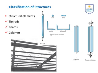
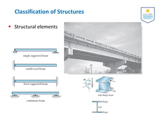
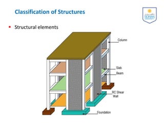
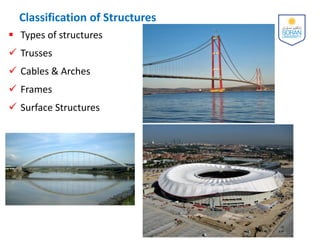
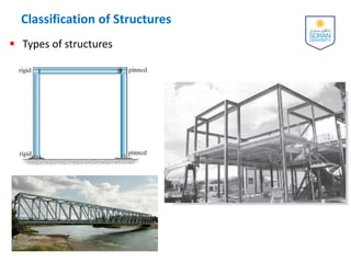
- Classification of structures into structural elements like beams and columns, and types like trusses and frames.
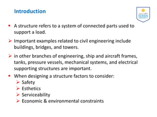
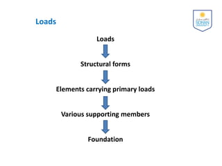
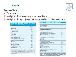
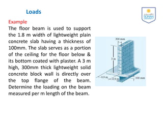
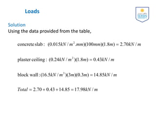
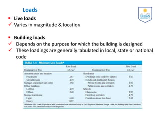
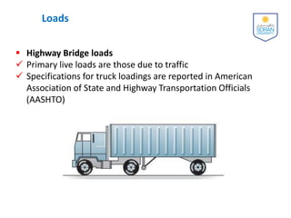
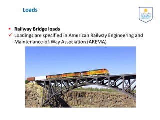
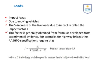
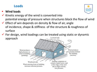
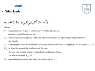
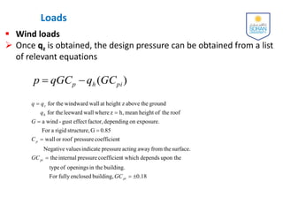
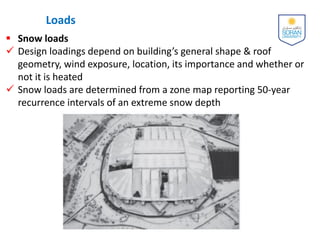
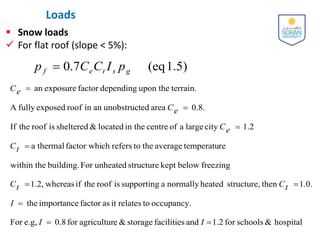
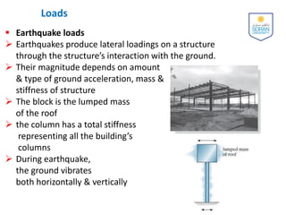
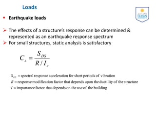
- Various types of loads structures must support, such as dead loads from structural weight, live loads from occupancy, and environmental loads from wind, snow, and earthquakes.
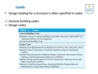
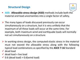
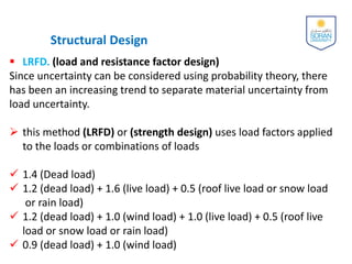
- Approaches to structural design, including allowable stress design (ASD) which incorporates uncertainties into a single safety factor, and load and resistance factor design (LRFD) which separates uncertainties.


![Part 1[Autosaved].pptx](https://cdn.slidesharecdn.com/ss_thumbnails/part1autosaved-221102081148-b5d4b037-thumbnail.jpg?width=640&height=640&fit=bounds)


![[Deck] What's New in Spark-Iceberg Integration via DSV2.pptx](https://cdn.slidesharecdn.com/ss_thumbnails/deckwhatsnewinspark-icebergintegrationviadsv2-260210005337-25955b12-thumbnail.jpg?width=640&height=640&fit=bounds)

