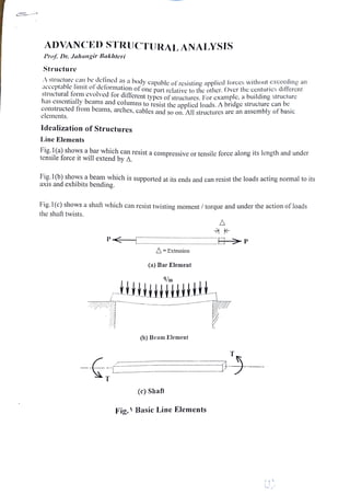
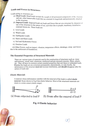
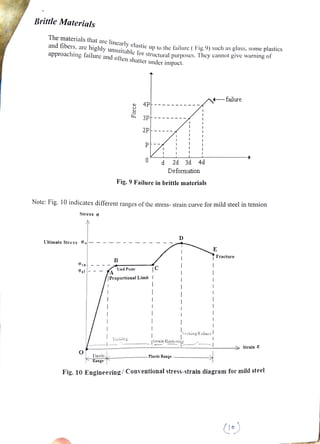
ADVANCED STRUCTURALANALYSIS
Prof. Dr. Jahangir Bakhteri
Structure
A
structure can be delined as a body capable ofresistine applicd forces without cxCCcding an
acceptable Imit ofdeformation of one part rclative to the oher.Over the centurics differcnt
structural formevolved for diflerent tvpcs of siructures. For examplc,a building structure
has essentially bcams and columns toresist theapplicd loads. A bridgcstructure can be
constructed fronm beams, arches, cables and so on. Allstructures are anassembly of 0dsiG
elements.
Idealization of Structures
LineElements
Fig.1(a) shows a bar which can resist a compressive or tensile force along its length and under
tensile force it will extend by A.
Fig.1(b) shows a beam which is supported at its ends and can resist the loads acting normal to its
axis and exhibits bending.
Fig.l(c) showsa shaft which can resist twisting moment /torque and under the action of loads
the shaft twists.
P
=Extension
(a) Bar Element
4/m
(b) Beam Element
(c) Shaft
Fig. )Basic Line Elements
Continuum Elements
Fig. 2(a) shows aslab or plate which resists loads applicd normal to the plate and because ofits
two-dimensionalnature its behavior is more complex.
Fig. 2(b) showsawallwhich, like abar resists compressive and tensile loads applicd to it but
behave as two dimensional. The above elenments are called continuum clements because their
length and breadth are much larger than thei thicknesses.
Fig. 2(c) shows a typicalstructure assembled from two-dimensional elements which can be
described as a three-dimensional.
Fig. 2(d) indicates the cross-sectionofadam structure which can best to be describedas three
dimensional model.
(a) slab or plate
(©) a building assembled from slab &
wall elements
(b)wall
(d) section of a dam
Fig. 2 Continuum Elements, 2-D & 3-D
G.L
Types of Joints
Structures are assembled by joining clements at clements intersections.
Insteel structures, the joints are joined bywelding or bolting.
In reintorcedconcrete structures, the jointismnade monolithic by proper reinforcement systems.
Fig. 3
representssome typical joints connecting bcams andcolumns
(a) Monolitithic joint in RCC
Types of Supports
Welds
(b) Welded joint at steel
structures
Fig. 3
Joints at bcam-column junction
support and fixed support.
(a) Roller support
on it.
Ideal types of"support joints" are classified as pinned or hinged support, roller
(c) Joint rotation at a
rigid-joint
(d) Joint rotation at a
pin-joint
Fig. 4(a) indicates schematic conventional representations ofaroller support and the force acting
Conventional representation ofsupport Nature of forcestransmitted
Fig. 4(a) Schematic representation of roller support
(6) Hinged or Pinned support
A
hinged support resists both horizontal and vertical movements but allows unrestrictcd
rotational movement 1.e. it support the forces pctino in horizontal and vertical directions as
shown in Fig. 4(b).
(c) Fixed support
Fig. 4(b) Schematic representation of pinned or hinged support
(d) Ball and socket support
in the Fig. 4(d)
Afixed support is achieved by connecting a member to a heavy foundation which resists
horizontal, vertical and rotational movements. Therefore, at a fixed support the forces acting are
a vertical force, a horizontal force and a couple as shown in theFig. 4(c).
M
Fig. 4(d) Ball and
socket support
Ry
R
O
Ry
Rx
Fig. 4(c) Schematic representation of a fixed support
A
balland socket support can transmit forces in three-dimension namelyR,R,and R as shown
Rx
R
Rz
R
0 Rigidsupportin space
A
rigidsupport n
sPee resists lorees and moments in x. yand zdircctions i,c. R, RR.M.
Mand Mas showninthe Fig. 4(c).
Fig. 4(c) Rigid supPport in space
Principle of Superposition
The main reason for assuming linear behavior ofstructures or linear load-deformation
relationship isthat it allows the use ofthe principle ofsuperposition. The principle states that the
displacements resulting from each ofamember forces may be added to obtain the displacements
resulting from the sum ofthe forces.
P
Asan example consider the cantilever beam shown in Fig. 5.The deflections caused by the three
separate loads are shown in Fig. 5(a). The same final deflections would result if all the three
loads are applied together as shown in Fig.5 (b)
1
P
P
-A33
(a) Deflections due toloads applied separately
Aj=AtA12+A13
P
R
A=A1tA22+A23
M,
k-A3=Ag|tAsztAss
(b) Deflections due to all loads applied together
Fig.5 Priciple of Superposition
R
Sign Convention in
Structural Analysis
An essential part otstructural analysis is the adonlion of an appropriate sign conventi0n tor
representing forces iand
displacements.
For aglobal A, Yand Zcoordinates syslen aechown in Eio.5the positive dircction of the forces
coincides with the direction of global coordinateaves and the moments follow the right-hand
screw rule.
Fig. 5Sign Convention System
(a) Axial force: An axial force is considered positive when it produces tension in the
member. Acompressive force is therefore negative.
(c)
(b) Shear force: Shear force which tends to Shear the member as shown in Fig.(a) is positive.
The positive shear force forms aclockwise couple on asegment
Fig.(a) Positive Shear
Bending Moment: The moment which produces compressive stresses in the top fiber or
tension in the bottom fiber is positive as shown in Fig.(b).
M M
Fig.(b) Positive Moment
(4)
In the jointconvention, thec momentthat t.,to toslate the joint clockwisc or the member end
anti-clockwiseis denoted positive as shown in Fig.(c).
(d) Twist:The twist moment is considered nositive as shown in Fig.(d). The positive twist
hand
corresponds to the right/screw rule.
Equilibrium:
The fundamental requirement ofequilibrium isconcerned with the guarantee that astructure, or
any of its parts, willnot move.
SF =0
The laws governing the motion of bodies,published by Isaac Newton in 1687 are called
Newton'sLaws. The particular cases of these laws governing equilibrium, i.e. the lack of motion
are of basic importance in structural theory and the structures are designed based on them.
The conditions of equilibrium are best established with reference to coordinate axes X. Yand Z.
Thus for static equilibrium, the algebraic sumn of all the forces along coordinate axes must be
zero, or mathematically,
SF =0
y
Fig.(c) Positive Moment
EF =0
ZM =0
SM =0
Fig.(d) Positive Twist
ZM =0
7)
Loads and Forces in Struetures
Loads acting in structures are:
(a) Dead Loads: Dead loads includethe weipht of all permancntcomponcnts of the structurc
and any other immovable loads that are constant in nagnitude and permancntly attached
tothe structure.
(b)ZmpOsed Loads: Imposed loads are loads and forces that act on a structure by character of
use of the structure to the nature of use, activities due to people, machinery installation,
externalforces etc. These loads are:
i) Live Loads
ii) Wind Loads
i) Earthquake Loads
iv) Snow and Rain Loads
v) Soil and Hydrostatic Forces
vi) Erection Loads
vii) Other Forces; such as impact, vibration, temperature effects, shrinkage, creep and forces
due to the settlement of foundations.
TheEssential Properties of Structural Materials
There are various types ofmaterials used in the construction ofstructures such as: stone
and masonry, wood,steel, aluminum, reinforced and pre-stressed concrete, fibers, plastic,
etc. They all have in common certain essential properties that suit them to withstand loads.
Whether the loads acton astructure permanently, intermittently, or only briefly, the
defornmation ofthe structure must not increase indefinitely, and should disappear after the
action of loads end.
Elastic Materials
Amaterial whose deformation vanishes with the removal ofthe loads is called elastic
material. Beam shown in Fig.6 has elastic behavior. Most ofthe structural materials are
elastic to certain extent (elastic range).
P
P=0
d=0
(a) Beam subjected to load P (b) Beam after the removal ofload P
Fig. 6 Elastic behavior
Linearly ElasticMaterials
Whenthe
deformation of a
materialis direetly proportionaltothe applicd loads,the material
is called lincar elastie as shownin Fig.7. Thus, if abcam made from lincar clastic material
detlects onc inch under a vertical load of 10 kips. it will deflect 2inches under 20 kips
loads.
(a)Beamn subjected to load P
(c)Beam after removal of the load
Plastic Materials
Fig.7 Lincarly elasticbehavior
P
(b) Beam subjected to load 2P
P=0
d=0
(a)Beam subjected toload P
P=0
When the total deformation in a material does not vanish by removing the loads, the
materialis said to behave plasticaly as shown in Fig.8.The load at which amaterial starts
behaving in plastic manner is called yield load or yield point.
2P
d#0
(b)Bearm subjected to load 2P
(c)Beam after rermnoval of the load
Fig. &
Plastic behavior
2P
2d
3d
Brittle Materials
The materials that arelincarly clastie upto the failure ( Fig.9) such as glass, some plastics
and fibers, are highly unsuitable for structuralpurposes. They cannot give warning of
approaching failure and ofen shatter under impact.
Stress o
Ultimate Stress Ou
Cyp
Opl
Elastic,
Range
FA
Note: Fig. 10indicates different ranges ofthe stress- strain curve for mild steel in tension
Force
B
4P
WiedPoint
3P
Fig. 9 Failure in brittle materials
Yielding
2P
2d 3d 4d
Deformation
Proportional Limit
D
Plastic Range
Strain Hardening
E
Necking/Failurel
-failure
Fracture
Strain &
Fig. 10 Engineering/Conventional stress-strain diagram for mild steel
()

chapter 1 structural analysis course for

  • 1.
    ADVANCED STRUCTURALANALYSIS Prof. Dr.Jahangir Bakhteri Structure A structure can be delined as a body capable ofresistine applicd forces without cxCCcding an acceptable Imit ofdeformation of one part rclative to the oher.Over the centurics differcnt structural formevolved for diflerent tvpcs of siructures. For examplc,a building structure has essentially bcams and columns toresist theapplicd loads. A bridgcstructure can be constructed fronm beams, arches, cables and so on. Allstructures are anassembly of 0dsiG elements. Idealization of Structures LineElements Fig.1(a) shows a bar which can resist a compressive or tensile force along its length and under tensile force it will extend by A. Fig.1(b) shows a beam which is supported at its ends and can resist the loads acting normal to its axis and exhibits bending. Fig.l(c) showsa shaft which can resist twisting moment /torque and under the action of loads the shaft twists. P =Extension (a) Bar Element 4/m (b) Beam Element (c) Shaft Fig. )Basic Line Elements
  • 2.
    Continuum Elements Fig. 2(a)shows aslab or plate which resists loads applicd normal to the plate and because ofits two-dimensionalnature its behavior is more complex. Fig. 2(b) showsawallwhich, like abar resists compressive and tensile loads applicd to it but behave as two dimensional. The above elenments are called continuum clements because their length and breadth are much larger than thei thicknesses. Fig. 2(c) shows a typicalstructure assembled from two-dimensional elements which can be described as a three-dimensional. Fig. 2(d) indicates the cross-sectionofadam structure which can best to be describedas three dimensional model. (a) slab or plate (©) a building assembled from slab & wall elements (b)wall (d) section of a dam Fig. 2 Continuum Elements, 2-D & 3-D G.L
  • 3.
    Types of Joints Structuresare assembled by joining clements at clements intersections. Insteel structures, the joints are joined bywelding or bolting. In reintorcedconcrete structures, the jointismnade monolithic by proper reinforcement systems. Fig. 3 representssome typical joints connecting bcams andcolumns (a) Monolitithic joint in RCC Types of Supports Welds (b) Welded joint at steel structures Fig. 3 Joints at bcam-column junction support and fixed support. (a) Roller support on it. Ideal types of"support joints" are classified as pinned or hinged support, roller (c) Joint rotation at a rigid-joint (d) Joint rotation at a pin-joint Fig. 4(a) indicates schematic conventional representations ofaroller support and the force acting Conventional representation ofsupport Nature of forcestransmitted Fig. 4(a) Schematic representation of roller support
  • 4.
    (6) Hinged orPinned support A hinged support resists both horizontal and vertical movements but allows unrestrictcd rotational movement 1.e. it support the forces pctino in horizontal and vertical directions as shown in Fig. 4(b). (c) Fixed support Fig. 4(b) Schematic representation of pinned or hinged support (d) Ball and socket support in the Fig. 4(d) Afixed support is achieved by connecting a member to a heavy foundation which resists horizontal, vertical and rotational movements. Therefore, at a fixed support the forces acting are a vertical force, a horizontal force and a couple as shown in theFig. 4(c). M Fig. 4(d) Ball and socket support Ry R O Ry Rx Fig. 4(c) Schematic representation of a fixed support A balland socket support can transmit forces in three-dimension namelyR,R,and R as shown Rx R Rz R
  • 5.
    0 Rigidsupportin space A rigidsupportn sPee resists lorees and moments in x. yand zdircctions i,c. R, RR.M. Mand Mas showninthe Fig. 4(c). Fig. 4(c) Rigid supPport in space Principle of Superposition The main reason for assuming linear behavior ofstructures or linear load-deformation relationship isthat it allows the use ofthe principle ofsuperposition. The principle states that the displacements resulting from each ofamember forces may be added to obtain the displacements resulting from the sum ofthe forces. P Asan example consider the cantilever beam shown in Fig. 5.The deflections caused by the three separate loads are shown in Fig. 5(a). The same final deflections would result if all the three loads are applied together as shown in Fig.5 (b) 1 P P -A33 (a) Deflections due toloads applied separately Aj=AtA12+A13 P R A=A1tA22+A23 M, k-A3=Ag|tAsztAss (b) Deflections due to all loads applied together Fig.5 Priciple of Superposition R
  • 6.
    Sign Convention in StructuralAnalysis An essential part otstructural analysis is the adonlion of an appropriate sign conventi0n tor representing forces iand displacements. For aglobal A, Yand Zcoordinates syslen aechown in Eio.5the positive dircction of the forces coincides with the direction of global coordinateaves and the moments follow the right-hand screw rule. Fig. 5Sign Convention System (a) Axial force: An axial force is considered positive when it produces tension in the member. Acompressive force is therefore negative. (c) (b) Shear force: Shear force which tends to Shear the member as shown in Fig.(a) is positive. The positive shear force forms aclockwise couple on asegment Fig.(a) Positive Shear Bending Moment: The moment which produces compressive stresses in the top fiber or tension in the bottom fiber is positive as shown in Fig.(b). M M Fig.(b) Positive Moment (4)
  • 7.
    In the jointconvention,thec momentthat t.,to toslate the joint clockwisc or the member end anti-clockwiseis denoted positive as shown in Fig.(c). (d) Twist:The twist moment is considered nositive as shown in Fig.(d). The positive twist hand corresponds to the right/screw rule. Equilibrium: The fundamental requirement ofequilibrium isconcerned with the guarantee that astructure, or any of its parts, willnot move. SF =0 The laws governing the motion of bodies,published by Isaac Newton in 1687 are called Newton'sLaws. The particular cases of these laws governing equilibrium, i.e. the lack of motion are of basic importance in structural theory and the structures are designed based on them. The conditions of equilibrium are best established with reference to coordinate axes X. Yand Z. Thus for static equilibrium, the algebraic sumn of all the forces along coordinate axes must be zero, or mathematically, SF =0 y Fig.(c) Positive Moment EF =0 ZM =0 SM =0 Fig.(d) Positive Twist ZM =0 7)
  • 8.
    Loads and Forcesin Struetures Loads acting in structures are: (a) Dead Loads: Dead loads includethe weipht of all permancntcomponcnts of the structurc and any other immovable loads that are constant in nagnitude and permancntly attached tothe structure. (b)ZmpOsed Loads: Imposed loads are loads and forces that act on a structure by character of use of the structure to the nature of use, activities due to people, machinery installation, externalforces etc. These loads are: i) Live Loads ii) Wind Loads i) Earthquake Loads iv) Snow and Rain Loads v) Soil and Hydrostatic Forces vi) Erection Loads vii) Other Forces; such as impact, vibration, temperature effects, shrinkage, creep and forces due to the settlement of foundations. TheEssential Properties of Structural Materials There are various types ofmaterials used in the construction ofstructures such as: stone and masonry, wood,steel, aluminum, reinforced and pre-stressed concrete, fibers, plastic, etc. They all have in common certain essential properties that suit them to withstand loads. Whether the loads acton astructure permanently, intermittently, or only briefly, the defornmation ofthe structure must not increase indefinitely, and should disappear after the action of loads end. Elastic Materials Amaterial whose deformation vanishes with the removal ofthe loads is called elastic material. Beam shown in Fig.6 has elastic behavior. Most ofthe structural materials are elastic to certain extent (elastic range). P P=0 d=0 (a) Beam subjected to load P (b) Beam after the removal ofload P Fig. 6 Elastic behavior
  • 9.
    Linearly ElasticMaterials Whenthe deformation ofa materialis direetly proportionaltothe applicd loads,the material is called lincar elastie as shownin Fig.7. Thus, if abcam made from lincar clastic material detlects onc inch under a vertical load of 10 kips. it will deflect 2inches under 20 kips loads. (a)Beamn subjected to load P (c)Beam after removal of the load Plastic Materials Fig.7 Lincarly elasticbehavior P (b) Beam subjected to load 2P P=0 d=0 (a)Beam subjected toload P P=0 When the total deformation in a material does not vanish by removing the loads, the materialis said to behave plasticaly as shown in Fig.8.The load at which amaterial starts behaving in plastic manner is called yield load or yield point. 2P d#0 (b)Bearm subjected to load 2P (c)Beam after rermnoval of the load Fig. & Plastic behavior 2P 2d 3d
  • 10.
    Brittle Materials The materialsthat arelincarly clastie upto the failure ( Fig.9) such as glass, some plastics and fibers, are highly unsuitable for structuralpurposes. They cannot give warning of approaching failure and ofen shatter under impact. Stress o Ultimate Stress Ou Cyp Opl Elastic, Range FA Note: Fig. 10indicates different ranges ofthe stress- strain curve for mild steel in tension Force B 4P WiedPoint 3P Fig. 9 Failure in brittle materials Yielding 2P 2d 3d 4d Deformation Proportional Limit D Plastic Range Strain Hardening E Necking/Failurel -failure Fracture Strain & Fig. 10 Engineering/Conventional stress-strain diagram for mild steel ()