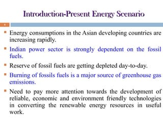
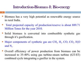
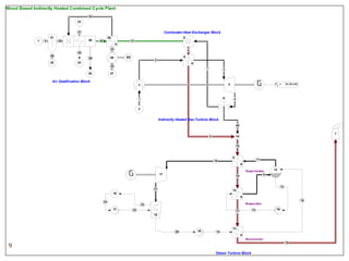
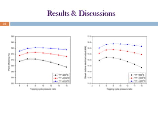
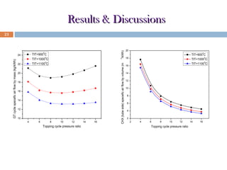
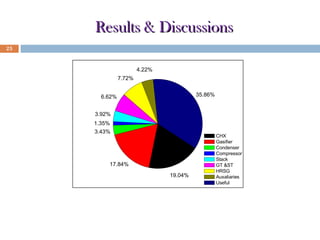
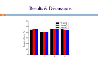
IV th International Conference on Advances in Energy Research

Presented By: P Mondal
PhD Scholar
Co-author: Dr. S Ghosh
Associate Professor
BENGAL ENGINEERING & SCIENCE UNIVERSITY, SHIBPUR
DEPARTMENT OF MECHANICAL ENGINEERING
HOWRAH-711103, W.B.
Overview
Introduction and perspective
Schematic of the proposed plant
Model development
Results and discussions
Conclusions
INTRODUCTION
AND
PERSPECTIVE
Introduction-Present Energy Scenario
4



Energy consumptions in the Asian developing countries are
increasing rapidly.



Indian power sector is strongly dependent on the fossil
fuels.



Reserve of fossil fuels are getting depleted day-to-day.



Burning of fossils fuels is a major source of greenhouse gas
emissions.



Need to pay more attention towards the development of
reliable, economic and environment friendly technologies
in converting the renewable energy resources in useful
work.
Introduction-Biomass & Bio-energy
5



Biomass has a very high potential as renewable energy source
in rural India.



Total projected capacity of production/reserve is about 889.71
Million Tones for the year 2010.



Solid biomass is converted into combustible synthetic gas
through it’s gasification.



Major components of synthetic gas are CH4, H2, CO, CO2, H2O
and N2.



Overall efficiency of power production from biomass can be
increased to 35-40% using gas turbine-steam turbine (GT-ST)
combined cycle integrating a gasifier in the system.
Introduction-Directly Heated GT Cycle
6

Problems

Tar and
Moisture

Lower in
longevity
of the GT

Particulate
Matter

Sulphur
Content

Corrosion , Erosion
and Deposition on
the turbine bladings
Introduction-Indirectly Heated GT Cycle
7

Solutions

No need of
cooling
arrangements

GT bladings
are safe from
corrosion and
erosion

Long ,
Economic and
Reliable
Operation

GT bladings
are safe from
particulate
deposition

Operates on
low cost and
dirt fuels
LAYOUT OF THE
PROPOSED
PLANT
Wood Based Indirectly Heated Combined Cycle Plant
34
23

Combustor-Heat Exchanger Block

27
1

21
5

20

25

26

30

H

5

31

33
26
22

6

28
28

29

6

2

24

H

32
25

7

3

27

Air Gasifiication Block

Pel =

4

3

9

1

30.00 kW

4

2

Indirectly Heated Gas Turbine Block
35

8

7

14
18

10

17

8

11
H
Superheater
9

16

12

12

21

15

19

H
24
11

15

Evaporator

23
22

13

17

16

10

20

18

14

13
H
Economizer
19

9
Steam Turbine Block
MODEL
DEVELOPMENT
Model Development
11

Characteristics of fuel used:
Parameter
Ultimate Analysis

Unit

Value

Mass percentage on wet basis

C

%

50

H

%

6

O

%

44

LHV (MJ/kg)

MJ/kg

16.3

Moisture

%

7.2
Model Development
12

Assumptions in the present study:


Post combustion temperature is limited to a value about 1300 0C.



The plant component operates at steady state.



No pressure and heat loss is assumed for the tubing and heat exchangers.



The compression and expansion processes are adiabatic (isentropic efficiencies of
90% for topping compressor and gas turbine, while the value is 85% for bottoming
steam turbine).



The inlet steam condition is 10 bar, 3500C. The condenser pressure is 0.1 bar.



For the HRSG, minimum pinch point temperature difference is set to15 0C. The
stack temperature is 1200C.
Thermodynamic Analyses-Energy
13

Gasifier Unit:
Gasification reaction:

CH a Ob + m(O2 + 3.76 N 2 ) → X 1H 2 + X 2CO + X 3CO2 + X 4 H 2O + X 5CH 4 + X 6 N 2

Water gas shift reaction and methane reaction:
CO + H 2O → CO2 + H 2
C + 2 H 2 = CH 4

Gasification efficiency:
ηgasi =

m p.g LHV p.g

mbiomass LHVbiomass

Assumptions:


Tar formation is not considered in this model.



The bed temperature of the gasifier is set to 8000C and the oxidant (air)/biomass ratio xOF is 1.8
Thermodynamic Analyses-Energy
14

CHX unit:
Combustion equation:
X 1 H 2 + X 2CO + X 3CO2 + X 4 H 2O + X 5CH 4 + X 6 N 2 + m ′(O2 + 3.76 N 2 ) →
X 7 CO2 + X 8 H 2O + ( X 6 + 3.76m′) N 2 + X 9O2

Post combustion temperature:
o

∑ X j ( h fj
j

+ ∆h) producergas + ∑ X j (h o + ∆h)air = ∑ X j (h o + ∆h) fluegas
fj
fj
j

j

Heat exchanging:
4.76m' (∆ h)air = X g ( ∆ h) f .g .m
Where Xg represents the number of moles of hot exhaust gases leaving the combustor
X g = X 6 + X 7 + X 8 + X 9 + 3.76m′
Thermodynamic Analyses-Energy
15

Combined cycle unit:
Compressor:
wc = c p,a (Tc,o - Tc,i )

Gas turbine:
wGT = c p,a (TGT,i -TGT,o )

Net GT output:
wnet = ( wGT − wc )η G

Gas mixture:
m f.g,m = m f + ma
m f cΔT + m c a ΔT = m
p, f
p,a

c

ΔT

f.g,m p, f.g,m

Steam generation rate:
m f . g ,m C p. f . g , m ∆T = ms ∆h
Thermodynamic Analyses-Energy
16

Steam turbine:
wST = (hST,i - hST,o )η G

Pump:
w p = (hp,o - h p,i )ηp

Net combined output:
wnet = ( wGT − wc )ηG + ( wST − w p )

First law efficiency:
ηCC =

wnet
mbiomass LHVbiomass
Thermodynamic Analyses-Exergy
17

Thermo-mechanical exergy:
ei = (hi - ho ) - To (si - so )

Where,
hi - ho =

Ti

∫

To

c p dT

P
dT
si - so = ∫ c p
- Rln i
To
T
P
o
Ti

Fuel exergy:
Ex fuel =mbiomass LHVβ
biomass

Where multiplication factor-β ,
1.044 +0.0160
β=

H
O
H
- 0.34493 (1+0.0531 )
C
C
C
O
1 - 0.4124
C
Thermodynamic Analyses-Exergy
18

Specific chemical exergy of producer gas :
X1 + X 2

X1
ch
eH 2 +
+X 3 +X 4 +X 5 +X 6

X1 + X 2

X2
ch
eCO +
+X3 +X 4 +X5 +X 6

X1 + X 2

ch
ebiomass =

X5
ch
eCH 4
+X3 +X 4 +X5 +X 6

Exergetic efficiency:
nexergetic =

Where ,

Exout

Exin

Exin = ∑ ( Exi )in + ∑ (Wi )in
Exout = ∑ ( Exi )out + ∑ (Wi )out
RESULTS AND
DISCUSSIONS
Results & Discussions
20

Product gas composition of the gasifier
Parameter
Gas Composition( mole fraction)
H2
CO
CO2
N2
CH4
H2 O
Oxidant-fuel ratio (xOF)
LHV of product gas mixture
Gasification efficiency

Unit

Value

%
%
%
%
%
%
MJ/kg
%

20.88
26.78
6.88
40.03
0.3
4.92
1.8
5.44
80.45
Results & Discussions
21

Base case performance of the plant
Parameter

Unit

Value

Biomass flow rate

kg/hr

23.4

Topping cycle pressure ratio

-

4

C

1000

kW

30

%

75

ST cycle output

kW

15.56

Combined work output

kW

45.56

Plant efficiency

%

37.383

GT inlet temperature
GT cycle output
Percentage of valve opening to CHX

0
Results & Discussions
22

17.0

38.5

16.5

Plant efficiency (%)

38.0
37.5
37.0
36.5
36.0
0

TIT=900 C
0
TIT=1000 C
0
TIT=1100 C

35.5
35.0
4

6

8

10

12

14

16

Topping cycle pressure ratio

Fig: Variation of plant efficiency with
GT block pressure ratio.

Steam turbine electrical output (kW)

39.0

16.0
15.5
15.0
14.5
14.0
0

TIT=900 C
0
TIT=1000 C
0
TIT=1100 C

13.5
13.0
2

4

6

8

10

12

14

16

Topping cycle pressure ratio

Fig: Variation of steam turbine
electrical output with GT block
pressure ratio.
Results & Discussions
0

20
18
16
14
12
10
4

6

8

10

12

14

16

Topping cycle pressure ratio

Fig: Variation of specific air flow by
mass with pressure ratio.

CHX (tube side) specefic air flow by volume (m

22

3

TIT=900 C
0
TIT=1000 C
0
TIT=1100 C

24

GT cycle specefic air flow by mass (kg/kWh)

/kWh)

23

20
0

TIT=900 C
0
TIT=1000 C
0
TIT=1100 C

18
16
14
12
10
8
6
4
2
2

4

6

8

10

12

14

16

Topping cycle pressure ratio

Fig: Variation of CHX (tube side)
specific air flow by volume with
pressure ratio.
Results & Discussions
24

Percentage of valve opening to CHX

Turbine Inlet Temperature
(0C)

Percentage of valve opening
(%)

900
1000
1100

58
75
97
Results & Discussions
25

4.22%
7.72%
35.86%

6.62%
3.92%
1.35%
3.43%

17.84%
19.04%

CHX
Gasifier
Condenser
Compressor
Stack
GT &ST
HRSG
Auxaliaries
Useful

Fig: Component exergy loss and useful exergy of the
plant at TIT=10000C.
Results & Discussions
26

120
0

TIT=900 C
0
TIT=1000 C
0
TIT=1100 C

Exergetic efficiency (%)

100

80

60

40

20

0
1

2

3

4

1: CHX 2: Gasifier 3: HRSG 4: GT & ST
Fig: Exergetic efficiency of the plant components at different TIT’s.
CONCLUSIONS
Conclusions
28

Thermodynamic analyses of a novel configuration (biomass
based indirectly heated combined cycle ) has been carried out in
this paper.
The efficiency of the proposed plant attains a maximum at
particular pressure ratio range (6-9) and individual turbine inlet
temperature (TIT).
For a particular pressure ratio the efficiency value increases at
higher TIT.
Size of the topping cycle components as well as CHX unit
decreases as pressure ratio increases at individual TIT. Also the
size of the said units are getting lowered at higher TIT’s
Conclusions
29

Major exergy losses occur at the gasifier, CHX unit, GT & ST
unit and HRSG unit for the plant.
Exergy loss for the other plant components are insignificant.
The exergetic efficiency of the gasifier and the CHX unit are
lower than that of other plant components due to the chemical
reactions takes place at the said units.
The exergy efficiency value of CHX unit is above 90% for the
plant at higher TIT.
References
30

1. Syred C., Fick W., Griffiths A.J., Syred N. (2000) Cyclone gasifier and cycle
combustor for the use of biomass derived gas in the operation of a small gas turbine in
co-generation plant, Fuel, 83, pp. 2381-2392.
2. Cycle-Tempo Software, (2012) Release 5 (TU Delft) (Website: http://www.cycletempo.nl/.)
3. Datta A., Ganguli R., Sarkar L. (2010) Energy and exergy analyses of an externally
fired gas turbine (egft), cycle integrated with biomass gasifier for distributed power
generation, Energy, 35, pp. 341-350.
4. Vera D., Jurado F., Mena de B., Schories G. (2011) Comparison between externally
fired gas turbine and gasifier-gas turbine system for the olive oil industry, Energy, 36,
pp. 6720-6730.
5. Barman N.S., Ghosh S., De S. (2012) Gasification of biomass in a fixed bed
downdraft gasifier-A realistic model including tar, Bioresource Technology, 107, pp.
505-511.
6. Ghosh S., De S. (2004) First and second law performance variations of coal
gasification fuel-cell based combined cogeneration plant with varying load, Proceedings
of the Institution of Mechanical Engineers, Part A: Journal of Power and Energy,
pp. 477-485.
References
31

7. Roy P.C. (2013) Role of biomass energy for sustainable development of rural India:
case studies, International Journal of Emerging Technology and Advanced Engineering,
Special Issue 3, ICERTSD 2013, pp. 577-582.
8. Energy Statistics (2012, Nineteenth Issue), Ministry of Statistics and Programme
Implementation, Govt. of India, 2012 (Website:
http://mospi.nic.in/Mospi_New/site/home.aspx).
9. Datta A., Mondal S., Dutta Gupta S. (2008) Perspective for the direct firing of
biomass as a supplementary fuel in combined cycle power plants, International Journal
of Energy Research, 32, pp. 1241-1257.
10. Soltani S., Mahamoudi S.M.S., Yari M., Rosen M.A. (2013) Thermodynamic
analyses of an externally fired gas turbine combined cycle integrated with biomass
gasification plant, Energy Conversion and Management, 70, pp. 107-115.
11. Fracnco A., Giannini N. (2005) Perspective for the use of biomass as a fuel in
combined cycle power plants, International Journal of Thermal Sciences, 44, pp.163177.
12. Bhattacharya A., Manna D., Paul B., Datta A. (2011) Biomass integrated
gasification combined cycle power generation with supplementary biomass firing:
Energy and exergy based performance analysis, Energy, 36, pp. 2599-2610.
Pradip Mondal
PhD Scholar
Dept of Mechanical Engineering
Bengal Engineering and Science University, Shibpur
Howrah-711103, West Bengal
e-mail: mondal.pradip87@gmail.com

234 pradip

  • 1.
    IV th InternationalConference on Advances in Energy Research Presented By: P Mondal PhD Scholar Co-author: Dr. S Ghosh Associate Professor BENGAL ENGINEERING & SCIENCE UNIVERSITY, SHIBPUR DEPARTMENT OF MECHANICAL ENGINEERING HOWRAH-711103, W.B.
  • 2.
    Overview Introduction and perspective Schematicof the proposed plant Model development Results and discussions Conclusions
  • 3.
  • 4.
    Introduction-Present Energy Scenario 4  Energyconsumptions in the Asian developing countries are increasing rapidly.  Indian power sector is strongly dependent on the fossil fuels.  Reserve of fossil fuels are getting depleted day-to-day.  Burning of fossils fuels is a major source of greenhouse gas emissions.  Need to pay more attention towards the development of reliable, economic and environment friendly technologies in converting the renewable energy resources in useful work.
  • 5.
    Introduction-Biomass & Bio-energy 5  Biomasshas a very high potential as renewable energy source in rural India.  Total projected capacity of production/reserve is about 889.71 Million Tones for the year 2010.  Solid biomass is converted into combustible synthetic gas through it’s gasification.  Major components of synthetic gas are CH4, H2, CO, CO2, H2O and N2.  Overall efficiency of power production from biomass can be increased to 35-40% using gas turbine-steam turbine (GT-ST) combined cycle integrating a gasifier in the system.
  • 6.
    Introduction-Directly Heated GTCycle 6 Problems Tar and Moisture Lower in longevity of the GT Particulate Matter Sulphur Content Corrosion , Erosion and Deposition on the turbine bladings
  • 7.
    Introduction-Indirectly Heated GTCycle 7 Solutions No need of cooling arrangements GT bladings are safe from corrosion and erosion Long , Economic and Reliable Operation GT bladings are safe from particulate deposition Operates on low cost and dirt fuels
  • 8.
  • 9.
    Wood Based IndirectlyHeated Combined Cycle Plant 34 23 Combustor-Heat Exchanger Block 27 1 21 5 20 25 26 30 H 5 31 33 26 22 6 28 28 29 6 2 24 H 32 25 7 3 27 Air Gasifiication Block Pel = 4 3 9 1 30.00 kW 4 2 Indirectly Heated Gas Turbine Block 35 8 7 14 18 10 17 8 11 H Superheater 9 16 12 12 21 15 19 H 24 11 15 Evaporator 23 22 13 17 16 10 20 18 14 13 H Economizer 19 9 Steam Turbine Block
  • 10.
  • 11.
    Model Development 11 Characteristics offuel used: Parameter Ultimate Analysis Unit Value Mass percentage on wet basis C % 50 H % 6 O % 44 LHV (MJ/kg) MJ/kg 16.3 Moisture % 7.2
  • 12.
    Model Development 12 Assumptions inthe present study:  Post combustion temperature is limited to a value about 1300 0C.  The plant component operates at steady state.  No pressure and heat loss is assumed for the tubing and heat exchangers.  The compression and expansion processes are adiabatic (isentropic efficiencies of 90% for topping compressor and gas turbine, while the value is 85% for bottoming steam turbine).  The inlet steam condition is 10 bar, 3500C. The condenser pressure is 0.1 bar.  For the HRSG, minimum pinch point temperature difference is set to15 0C. The stack temperature is 1200C.
  • 13.
    Thermodynamic Analyses-Energy 13 Gasifier Unit: Gasificationreaction: CH a Ob + m(O2 + 3.76 N 2 ) → X 1H 2 + X 2CO + X 3CO2 + X 4 H 2O + X 5CH 4 + X 6 N 2 Water gas shift reaction and methane reaction: CO + H 2O → CO2 + H 2 C + 2 H 2 = CH 4 Gasification efficiency: ηgasi = m p.g LHV p.g mbiomass LHVbiomass Assumptions:  Tar formation is not considered in this model.  The bed temperature of the gasifier is set to 8000C and the oxidant (air)/biomass ratio xOF is 1.8
  • 14.
    Thermodynamic Analyses-Energy 14 CHX unit: Combustionequation: X 1 H 2 + X 2CO + X 3CO2 + X 4 H 2O + X 5CH 4 + X 6 N 2 + m ′(O2 + 3.76 N 2 ) → X 7 CO2 + X 8 H 2O + ( X 6 + 3.76m′) N 2 + X 9O2 Post combustion temperature: o ∑ X j ( h fj j + ∆h) producergas + ∑ X j (h o + ∆h)air = ∑ X j (h o + ∆h) fluegas fj fj j j Heat exchanging: 4.76m' (∆ h)air = X g ( ∆ h) f .g .m Where Xg represents the number of moles of hot exhaust gases leaving the combustor X g = X 6 + X 7 + X 8 + X 9 + 3.76m′
  • 15.
    Thermodynamic Analyses-Energy 15 Combined cycleunit: Compressor: wc = c p,a (Tc,o - Tc,i ) Gas turbine: wGT = c p,a (TGT,i -TGT,o ) Net GT output: wnet = ( wGT − wc )η G Gas mixture: m f.g,m = m f + ma m f cΔT + m c a ΔT = m p, f p,a c ΔT f.g,m p, f.g,m Steam generation rate: m f . g ,m C p. f . g , m ∆T = ms ∆h
  • 16.
    Thermodynamic Analyses-Energy 16 Steam turbine: wST= (hST,i - hST,o )η G Pump: w p = (hp,o - h p,i )ηp Net combined output: wnet = ( wGT − wc )ηG + ( wST − w p ) First law efficiency: ηCC = wnet mbiomass LHVbiomass
  • 17.
    Thermodynamic Analyses-Exergy 17 Thermo-mechanical exergy: ei= (hi - ho ) - To (si - so ) Where, hi - ho = Ti ∫ To c p dT P dT si - so = ∫ c p - Rln i To T P o Ti Fuel exergy: Ex fuel =mbiomass LHVβ biomass Where multiplication factor-β , 1.044 +0.0160 β= H O H - 0.34493 (1+0.0531 ) C C C O 1 - 0.4124 C
  • 18.
    Thermodynamic Analyses-Exergy 18 Specific chemicalexergy of producer gas : X1 + X 2 X1 ch eH 2 + +X 3 +X 4 +X 5 +X 6 X1 + X 2 X2 ch eCO + +X3 +X 4 +X5 +X 6 X1 + X 2 ch ebiomass = X5 ch eCH 4 +X3 +X 4 +X5 +X 6 Exergetic efficiency: nexergetic = Where , Exout Exin Exin = ∑ ( Exi )in + ∑ (Wi )in Exout = ∑ ( Exi )out + ∑ (Wi )out
  • 19.
  • 20.
    Results & Discussions 20 Productgas composition of the gasifier Parameter Gas Composition( mole fraction) H2 CO CO2 N2 CH4 H2 O Oxidant-fuel ratio (xOF) LHV of product gas mixture Gasification efficiency Unit Value % % % % % % MJ/kg % 20.88 26.78 6.88 40.03 0.3 4.92 1.8 5.44 80.45
  • 21.
    Results & Discussions 21 Basecase performance of the plant Parameter Unit Value Biomass flow rate kg/hr 23.4 Topping cycle pressure ratio - 4 C 1000 kW 30 % 75 ST cycle output kW 15.56 Combined work output kW 45.56 Plant efficiency % 37.383 GT inlet temperature GT cycle output Percentage of valve opening to CHX 0
  • 22.
    Results & Discussions 22 17.0 38.5 16.5 Plantefficiency (%) 38.0 37.5 37.0 36.5 36.0 0 TIT=900 C 0 TIT=1000 C 0 TIT=1100 C 35.5 35.0 4 6 8 10 12 14 16 Topping cycle pressure ratio Fig: Variation of plant efficiency with GT block pressure ratio. Steam turbine electrical output (kW) 39.0 16.0 15.5 15.0 14.5 14.0 0 TIT=900 C 0 TIT=1000 C 0 TIT=1100 C 13.5 13.0 2 4 6 8 10 12 14 16 Topping cycle pressure ratio Fig: Variation of steam turbine electrical output with GT block pressure ratio.
  • 23.
    Results & Discussions 0 20 18 16 14 12 10 4 6 8 10 12 14 16 Toppingcycle pressure ratio Fig: Variation of specific air flow by mass with pressure ratio. CHX (tube side) specefic air flow by volume (m 22 3 TIT=900 C 0 TIT=1000 C 0 TIT=1100 C 24 GT cycle specefic air flow by mass (kg/kWh) /kWh) 23 20 0 TIT=900 C 0 TIT=1000 C 0 TIT=1100 C 18 16 14 12 10 8 6 4 2 2 4 6 8 10 12 14 16 Topping cycle pressure ratio Fig: Variation of CHX (tube side) specific air flow by volume with pressure ratio.
  • 24.
    Results & Discussions 24 Percentageof valve opening to CHX Turbine Inlet Temperature (0C) Percentage of valve opening (%) 900 1000 1100 58 75 97
  • 25.
    Results & Discussions 25 4.22% 7.72% 35.86% 6.62% 3.92% 1.35% 3.43% 17.84% 19.04% CHX Gasifier Condenser Compressor Stack GT&ST HRSG Auxaliaries Useful Fig: Component exergy loss and useful exergy of the plant at TIT=10000C.
  • 26.
    Results & Discussions 26 120 0 TIT=900C 0 TIT=1000 C 0 TIT=1100 C Exergetic efficiency (%) 100 80 60 40 20 0 1 2 3 4 1: CHX 2: Gasifier 3: HRSG 4: GT & ST Fig: Exergetic efficiency of the plant components at different TIT’s.
  • 27.
  • 28.
    Conclusions 28 Thermodynamic analyses ofa novel configuration (biomass based indirectly heated combined cycle ) has been carried out in this paper. The efficiency of the proposed plant attains a maximum at particular pressure ratio range (6-9) and individual turbine inlet temperature (TIT). For a particular pressure ratio the efficiency value increases at higher TIT. Size of the topping cycle components as well as CHX unit decreases as pressure ratio increases at individual TIT. Also the size of the said units are getting lowered at higher TIT’s
  • 29.
    Conclusions 29 Major exergy lossesoccur at the gasifier, CHX unit, GT & ST unit and HRSG unit for the plant. Exergy loss for the other plant components are insignificant. The exergetic efficiency of the gasifier and the CHX unit are lower than that of other plant components due to the chemical reactions takes place at the said units. The exergy efficiency value of CHX unit is above 90% for the plant at higher TIT.
  • 30.
    References 30 1. Syred C.,Fick W., Griffiths A.J., Syred N. (2000) Cyclone gasifier and cycle combustor for the use of biomass derived gas in the operation of a small gas turbine in co-generation plant, Fuel, 83, pp. 2381-2392. 2. Cycle-Tempo Software, (2012) Release 5 (TU Delft) (Website: http://www.cycletempo.nl/.) 3. Datta A., Ganguli R., Sarkar L. (2010) Energy and exergy analyses of an externally fired gas turbine (egft), cycle integrated with biomass gasifier for distributed power generation, Energy, 35, pp. 341-350. 4. Vera D., Jurado F., Mena de B., Schories G. (2011) Comparison between externally fired gas turbine and gasifier-gas turbine system for the olive oil industry, Energy, 36, pp. 6720-6730. 5. Barman N.S., Ghosh S., De S. (2012) Gasification of biomass in a fixed bed downdraft gasifier-A realistic model including tar, Bioresource Technology, 107, pp. 505-511. 6. Ghosh S., De S. (2004) First and second law performance variations of coal gasification fuel-cell based combined cogeneration plant with varying load, Proceedings of the Institution of Mechanical Engineers, Part A: Journal of Power and Energy, pp. 477-485.
  • 31.
    References 31 7. Roy P.C.(2013) Role of biomass energy for sustainable development of rural India: case studies, International Journal of Emerging Technology and Advanced Engineering, Special Issue 3, ICERTSD 2013, pp. 577-582. 8. Energy Statistics (2012, Nineteenth Issue), Ministry of Statistics and Programme Implementation, Govt. of India, 2012 (Website: http://mospi.nic.in/Mospi_New/site/home.aspx). 9. Datta A., Mondal S., Dutta Gupta S. (2008) Perspective for the direct firing of biomass as a supplementary fuel in combined cycle power plants, International Journal of Energy Research, 32, pp. 1241-1257. 10. Soltani S., Mahamoudi S.M.S., Yari M., Rosen M.A. (2013) Thermodynamic analyses of an externally fired gas turbine combined cycle integrated with biomass gasification plant, Energy Conversion and Management, 70, pp. 107-115. 11. Fracnco A., Giannini N. (2005) Perspective for the use of biomass as a fuel in combined cycle power plants, International Journal of Thermal Sciences, 44, pp.163177. 12. Bhattacharya A., Manna D., Paul B., Datta A. (2011) Biomass integrated gasification combined cycle power generation with supplementary biomass firing: Energy and exergy based performance analysis, Energy, 36, pp. 2599-2610.
  • 32.
    Pradip Mondal PhD Scholar Deptof Mechanical Engineering Bengal Engineering and Science University, Shibpur Howrah-711103, West Bengal e-mail: mondal.pradip87@gmail.com