Downloaded 119 times

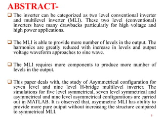


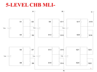


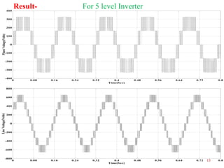
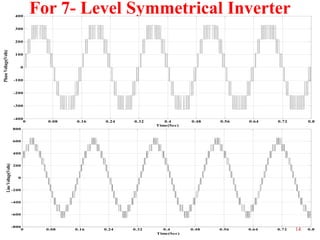

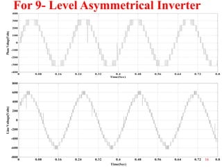
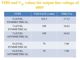
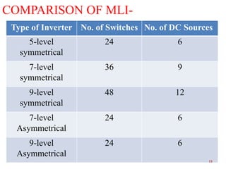


The document presents research on asymmetrical cascaded H-bridge multilevel inverters. It summarizes the structure and operation of 5-level, 7-level symmetrical, and 7-level and 9-level asymmetrical configurations. Simulation results show that asymmetrical configurations reduce harmonics without increasing components compared to symmetrical configurations. The conclusion is that asymmetrical multilevel inverters can produce more output levels without adding components by using different progression factors.


![6.[36 45]seven level modified cascaded inverter for induction motor drive app...](https://cdn.slidesharecdn.com/ss_thumbnails/6-36-45sevenlevelmodifiedcascadedinverterforinductionmotordriveapplications-111118182704-phpapp01-thumbnail.jpg?width=640&height=640&fit=bounds)