This document summarizes an electro-hydraulic braking system designed for autonomous vehicles. The system was developed to allow computer control of braking in addition to the original braking circuit for increased safety. It uses a pump and valves to permit control signals from the computer to stop the car independently of the original brakes. Tests showed the system could brake the vehicle similarly to a human driver without interfering with the existing brakes.
What is an Anti-Lock Braking System (ABS)?
History of ABS
Motivation for ABS Development
Principles for ABS Operation
ABS Components
Subaru Impreza ABS Application.
How does ABS work?
Anti-Lock Brake Types
ABS Configurations
Design Challenges
Advantages & Disadvantages
ABS Problems
What is an Anti-Lock Braking System (ABS)?
History of ABS
Motivation for ABS Development
Principles for ABS Operation
ABS Components
Subaru Impreza ABS Application.
How does ABS work?
Anti-Lock Brake Types
ABS Configurations
Design Challenges
Advantages & Disadvantages
ABS Problems
MODULE-I
Electric and Hybrid Vehicle technology: Introduction, LEV, TLEV, ULV & ZEV, Basic
components of Electric vehicles, Batteries suitable for electric vehicles, motor and controllers,
constructional features,
Basic factors to be considered for converting automobiles to electric vehicle, electric hybrid
vehicle, types - series and parallel hybrid, layouts, comparison, Power systems and control
systems, Different modes of operation for best usage. Regenerative braking,
Recent Trends in Automotive Power Plants: Stratified charged / lean burn engines –
Hydrogen Engines- Electric propulsion with cables – Magnetic track vehicles.
MODULE 11
Fuel Cells and Alternative energy systems: Introduction to fuel cells, Operational fuel cell
voltages, Proton Exchange membrane fuel cells, Alkaline Electrolyte fuel cells, Medium and
high temperature fuel cells, fuel and fuel chose, fuel processing, fuel cell stacks, Delivering
fuel cell power, Integrated Air supply and humidification concepts for fuel cell systems, A
comparison of High pressure and low pressure operation PEM Fuel cell systems, Fuel cell
Auxiliary systems,
Modern Developments in Automobiles: Air compression systems, Air powered vehicles,
Vehicle Automated Tracks: Preparation and maintenance of proper road network-National
highway network with automated roads and vehicles-Satellite control of vehicle operation for
safe and fast travel.
Module III
Modem electronic and micro control systems in automobiles: Electronically controlled
concealed headlight systems, LED and Audible warning systems Electro chromic mirrors,
automatic review mirrors, OBD II, Day time running lamps (DRL), Head up display, Travel
information systems, On board navigation system, Electronic climate control, Electronic cruise
control, Antilock braking system, Electronically controlled sunroof, Anti-theft systems,
Automatic door locks (ADL), engine management system, Electronic transmission control,
chassis control system, Integrated system
Vehicle Operation and Control: Computer Control for pollution and noise control and for fuel
economy-Transducers and operation of the vehicle like optimum speed and direction.
This ppt describes about the working of ABS and components, advantages and a short video clip explain clearly about the ABS. There also the be comparison for the car with ABS and without ABS in form of short GIF.
Active suspension System of Automobiles.Mayank khare
An active suspension system,has the capability to adjust itself continuously to changing road conditions. It "artificially" extends the design parameters of the system by constantly monitoring and adjusting itself, thereby changing its character on an ongoing basis. It's schizophrenic, if you will, but with a purpose. With advanced sensors and microprocessors feeding it information all the time, its identity remains fluid, contextual, amorphous. By changing its character to respond to varying road conditions, active suspension offers superior handling, road feel, responsiveness and safety.
Modern day automobile engines are made of many electronic and electrical components that constitute engine sensors, relays and actuators. All these electronic and electrical components work together to provide Engine Control Unit (ECU) with vital data required to govern the engine functionality effectively. Sensors send the information in very less time. Sensors used in engine are generally electro-mechanical type devices that monitor various engine parameters.
Transmission is a part of the car which connects the engine to the wheels. When car speeds up, the engine can not speed up in the same proportion, so there are gears involved which match the engine speed to the wheel speed so that we can drive faster or slower than the engine speed.
Electronic Power Steering (EPS) by Gaurav RaikarGauravRaikar3
This presentations describes electronic power steering types.
1.Hydraulic power steering system(HPS)
2.Electro-hydraulic power steering system(EHPS)
3.Electronic power system(EPS)
In the automotive industry there has been an increased emphasis on vehicle safety. Improvement in brake technology has greatly contributed to stable running of vehicles. Increased functionality has resulted in products like ABS, ESC, and brake assist. An example of the increased functionality of automotive brakes is improvement in control techniques for hydraulic brakes. Furthermore, in an effort to continue this improvement in functionality and reduction in environmental impact, automotive components manufacturers and car manufacturers are developing electromechanical brake (EMB) systems.
Many of newly developed electromechanical brake systems employ linear actuators such as ball-screws and ball-ramps (torque cams). However, when any of these linear actuators is used to develop the sufficient thrust required to brake a traveling vehicle, greater input torque is needed because the load conversion ratio with the linear actuator alone is insufficient. To design a more compact, lightweight electromechanical brake unit, the motor must be more compact. Therefore an independent reducer needs to be incorporated. Additionally, the electromechanical brake is situated in the “unsprung” section of the vehicle and will be subjected to violent vibration. Therefore it must be positively fretting-resistant.
The centerpiece of the current braking systems is a hydraulic assembly under the hood of the vehicle that brings together the electronic control unit, wheel pressure modulators, pressure reservoir, and electric pump. The interaction of mechanics and electronics is key to the success of the braking system. The microcomputer, software, sensors, valves, and electric pump work together to form the basis of the system.
Endurance Testing of Aircraft Electro-Hydraulic Actuator Using LabVIEWWaqas Tariq
In Aerospace Industry, Automated Test System at the qualification and certification laboratory improves characterization accuracy and plays a vital role to prove the airworthiness of the aircraft components. It is very helpful in achieving high quality standards of aircraft components by meeting the predefined qualification and certification test criteria. This paper outlines a comprehensive design and development of an Endurance Automated Test System for performing qualification and certification testing of Electro-Hydraulic (EH) Aircraft Actuator uses LabVIEW Graphical Test Software platform. This method is aimed at replacing the tedious and time consuming traditional method of performing the endurance testing for Aircraft Actuators.
Electro hydraulic system Components and their operationSrichandan Subudhi
After this presentation you will be knowing:
1.What are DCVs, its type and their uses
2.About Check Valves and pilot controlled check valves
3.What are solenoid actuated valves and their operation
4.What are proportional solenoid valves and their operation
5.Servo Valve Operation
6.Servo Valve Connector
An airborne wind turbine is a design concept for a wind turbine with a rotor supported in the air without a tower, thus benefiting from more mechanical and aerodynamic options.
I had done 1 month summer training on topic " AIR BRAKE SYSTEM USED IN LOCOMOTIVE " from LOCO workshop, LKO....students who are doing so....this file can help them to prepare project file...
An airborne wind turbine is a design concept for a wind turbine with a rotor supported in the air without a tower, thus benefiting from more mechanical and aerodynamic options.
Shared Steering Control between a Driver and an Automation: Stability in the ...paperpublications3
Abstract: Now-a-days the Automatic control has been increasingly implemented for vehicle control system. Especially the steering control is essential for preventing accidents. In the existing systems there is no fully automatic steering control and it has serious problems. When it is made automatic, the system complexity is more. So, the shared steering concept is used in the proposed system to avoid accidents. In this, the position of the road is found using the web camera installed in front of the vehicle which is connected to the PC installed with MATLAB. Using MATLAB the image is processed to check the road characteristics. This paper presents an advanced driver assistance system (ADAS) for lane keeping, together with an analysis of its performance and stability with respect to variations in driver behavior. The automotive ADAS proposed is designed to share control of the steering wheel with the driver in the best possible way. Its development was derived from an H2-Preview optimization control problem, which is based on a global driver–vehicle–road (DVR) system. The DVR model makes use of a cybernetic driver model to take into account any driver–vehicle interactions. Such a formulation allows 1) Considering driver assistance cooperation criteria in the control synthesis, 2) improving the performance of the assistance as a cooperative copilot, and 3) analyzing the stability of the whole system in the presence of driver model uncertainty. The developed assistance system improved lane-keeping performance and reduced the risk of a lane departure accident. Good results were obtained using several criteria for human–machine cooperation. Poor stability situations were successfully avoided due to the robustness of the whole system, in spite of a large range of driver model uncertainty.
Optimization of automobile active suspension system using minimal orderIJECEIAES
This paper presents an analysis and design of linear quadratic regulator for reduced order full car suspension model incorporating the dynamics of the actuator to improve system performance, aims at benefiting: Ride comfort, long life of vehicle, and stability of vehicle. Vehicle’s road holding or handling and braking for good active safety and driving pleasure and keeping vehicle occupants comfortable and reasonably well isolated from road noise, bumps, and vibrations are become a key research area conducted by many researchers around the globe. Different researchers were tested effectiveness of different controllers for different vehicle model without considering the actuator dynamics. In this paper full vehicle model was reduced to a minimal order using minimal realization technique. The entire system responses were simulated in MATLAB/Simulink environment. The effectiveness of linear quadratic regulator controller was compared for the system model with and without actuator dynamics for different road profiles. The simulation results were indicated that percentage reduction in the peak value of vertical and horizontal velocity for the linear quadratic regulator with actuator dynamics relative to linear quadratic regulator without actuator dynamics was 28.57%. Overall simulation results were demonstrated that proposed control scheme has able to improve the effectiveness of the car model for both ride comfort and stability.
People using old second hand cars in cities, particularly novice drivers engage irrelevant gears; this in turn leads to fuel wastage and importing more petrol and diesel. One simple solution is to educate and alert the drivers. In the current paper we explain how to design a low cost, add-on type of s assembly unit which can be fitted on any existing vehicle.
Modeling of Dynamical System Piloted by Discrete Subsystem Based on Bond Grap...IJECEIAES
This paper is a contribution to the analysis and modeling of a mechatronic system with dynamic behavior that is controlled by a digital computer. In this paper, a bibliographic research on mechatronic systems is presented by specifying a case study of the Anti-lock Braking System (ABS). Then, a methodology of systemic modeling of the ABS system based on two methods Structured Analysis Design Technique (SADT) and bond graph (BG) is proposed. The model created is validated with three software programs: CarSim, 20 Sim and Simulink.
Fuzzy rules incorporated skyhook theory based vehicular suspension design for...IJERA Editor
The vehicle suspension system supports and isolate the vehicle body and payload from road vibrations due to surface roughness by maintaining a controllable damping traction force between tires and road surface. In modern luxury vehicles semi active suspension system are offering both the reliability and accuracy that has enhanced the passenger ride comfort with less power demand. In this paper we have proposed the design of a hybrid control system having a combination of skyhook theory with fuzzy logic control and applied on a semi-active vehicle suspension system for its ride comfort enhancement. A two degree of freedom dynamic model is simulated using Matlab/Simulink for a vehicle equipped with semi-active suspension system with focused on the passenger‟s ride comfort performance.
Universal Motors (UM) are normally used for driving portable apparatus such as hand tool machines, vacuum cleaners and most domestic apparatus. The importance of UM is due to its own advantages such as high starting torque, very powerful in relation to its small size, having a variable speed; and lower cost. So, this paper focus on UM speed control under variable loading conditions. A mathematical model for UM is designed. Two controllers are proposed for controlling the motor speed, output rate controller and output reset controller. Ant Colony Optimization (ACO) is proposed for tuning the controller’s parameters due to its impact on solving different optimization problems. It possesses fast convergence, minimum algorithm parameters required, lower consecution time and give optimal results without needing large number of iterations. The results are compared and discussed accurately, which show the proposed tuning technique work well and give optimal results for both controllers.
Advancement in Suspension System: - A Reviewdbpublications
The purpose of presenting this review paper is to provide in-depth information about suspension system. It explains the comforts and safety of the passenger. It illustrates the importance of the suspension system in automobile. Vehicle suspensions systems typically rated by its ability to provide good road handling and improve passenger comfort. It also says the improvement that has been taken place in the suspension system for a better ride and driver comfort. The foremost suspension was Bose electromagnetic suspension. The advancement that has been used in the suspension system is for cars. The three technologies that had made cars even better than first that is: - 1. DRC (dynamic ride control), 2. Magnetic Dampers (AUDI R8), 3.Active Curve Tilting. Further it illustrates the specification and causes of the invention and it also describes the electromagnetic active suspensions. The future trends of automotive suspensions are due to simple structure, high-bandwidth, accurate and flexible force control, high ride quality, good handling performance, and energy regeneration. It says the application and better enrolment of suspension system.
Linear Control Technique for Anti-Lock Braking SystemIJERA Editor
Antilock braking systems are used in modern cars to prevent the wheels from locking after brakes are applied. The dynamics of the controller needed for antilock braking system depends on various factors. The vehicle model often is in nonlinear form. Controller needs to provide a controlled torque necessary to maintain optimum value of the wheel slip ratio. The slip ratio is represented in terms of vehicle speed and wheel rotation.
In present work first of all system dynamic equations are explained and a slip ratio is expressed in terms of system variables namely vehicle linear velocity and angular velocity of the wheel. By applying a bias braking force system, response is obtained using Simulink models. Using the linear control strategies like PI-type the effectiveness of maintaining desired slip ratio is tested. It is always observed that a steady state error of 10% occurring in all the control system models.
Design and analysis of a new brake-by-wire system using machine learning IJECEIAES
One of the main aims of the recent research on brake-by-wire systems is to decrease mechanical components. In this paper, we propose replacing the brake pedal with a driving wheel that is fully covered by pressure braking batch sensors. The new mechanism for braking translates pressure exerted through the driver’s hands on the driving wheel to a corresponding electrical signal. A proposed design for the pressure braking batch (PBB) is made out of a mesh of conducting threads separated by a resistive sheet. To the best of our knowledge, this idea has not been raised before in other research papers. Different people have different muscle strengths and so the problem of identifying the intention of the user when pressing the PBB is tackled. For this aim, a new dataset of its kind is created by several volunteers. From each volunteer, age, gender, body mass index (BMI), and maximum pressure exerted on the driving wheel are collected. Using Weka software, the detection accuracy is calculated for a new volunteer to know the intention of his/her pressure on PBB. Among the three algorithms tried, the regression tree gives the best results in predicting the class of the pressure exerted by the volunteers.
Development of Russian Driverless Electric VehicleIJAAS Team
This article overviews the history of development of driverless vehicles both in Russia and the World. Foreign experience of development of driverless vehicles, including electric traction, is analyzed. Main stages of creation of experimental NAMI driverless electric vehicle are revised. Main engineering solutions are described concerning development of advanced NAMI driverless electric vehicle, its major components and control systems. Projects aimed at environmental safety of passengers in NAMI driverless electric vehicle are exemplified. Results of bench scale and running tests of NAMI driverless electric vehicle are summarized. Major advantages of driverless energy efficient and environmentally clean transport are demonstrated.
The Art of the Pitch: WordPress Relationships and SalesLaura Byrne
Clients don’t know what they don’t know. What web solutions are right for them? How does WordPress come into the picture? How do you make sure you understand scope and timeline? What do you do if sometime changes?
All these questions and more will be explored as we talk about matching clients’ needs with what your agency offers without pulling teeth or pulling your hair out. Practical tips, and strategies for successful relationship building that leads to closing the deal.
PHP Frameworks: I want to break free (IPC Berlin 2024)Ralf Eggert
In this presentation, we examine the challenges and limitations of relying too heavily on PHP frameworks in web development. We discuss the history of PHP and its frameworks to understand how this dependence has evolved. The focus will be on providing concrete tips and strategies to reduce reliance on these frameworks, based on real-world examples and practical considerations. The goal is to equip developers with the skills and knowledge to create more flexible and future-proof web applications. We'll explore the importance of maintaining autonomy in a rapidly changing tech landscape and how to make informed decisions in PHP development.
This talk is aimed at encouraging a more independent approach to using PHP frameworks, moving towards a more flexible and future-proof approach to PHP development.
UiPath Test Automation using UiPath Test Suite series, part 3DianaGray10
Welcome to UiPath Test Automation using UiPath Test Suite series part 3. In this session, we will cover desktop automation along with UI automation.
Topics covered:
UI automation Introduction,
UI automation Sample
Desktop automation flow
Pradeep Chinnala, Senior Consultant Automation Developer @WonderBotz and UiPath MVP
Deepak Rai, Automation Practice Lead, Boundaryless Group and UiPath MVP
JMeter webinar - integration with InfluxDB and GrafanaRTTS
Watch this recorded webinar about real-time monitoring of application performance. See how to integrate Apache JMeter, the open-source leader in performance testing, with InfluxDB, the open-source time-series database, and Grafana, the open-source analytics and visualization application.
In this webinar, we will review the benefits of leveraging InfluxDB and Grafana when executing load tests and demonstrate how these tools are used to visualize performance metrics.
Length: 30 minutes
Session Overview
-------------------------------------------
During this webinar, we will cover the following topics while demonstrating the integrations of JMeter, InfluxDB and Grafana:
- What out-of-the-box solutions are available for real-time monitoring JMeter tests?
- What are the benefits of integrating InfluxDB and Grafana into the load testing stack?
- Which features are provided by Grafana?
- Demonstration of InfluxDB and Grafana using a practice web application
To view the webinar recording, go to:
https://www.rttsweb.com/jmeter-integration-webinar
UiPath Test Automation using UiPath Test Suite series, part 4DianaGray10
Welcome to UiPath Test Automation using UiPath Test Suite series part 4. In this session, we will cover Test Manager overview along with SAP heatmap.
The UiPath Test Manager overview with SAP heatmap webinar offers a concise yet comprehensive exploration of the role of a Test Manager within SAP environments, coupled with the utilization of heatmaps for effective testing strategies.
Participants will gain insights into the responsibilities, challenges, and best practices associated with test management in SAP projects. Additionally, the webinar delves into the significance of heatmaps as a visual aid for identifying testing priorities, areas of risk, and resource allocation within SAP landscapes. Through this session, attendees can expect to enhance their understanding of test management principles while learning practical approaches to optimize testing processes in SAP environments using heatmap visualization techniques
What will you get from this session?
1. Insights into SAP testing best practices
2. Heatmap utilization for testing
3. Optimization of testing processes
4. Demo
Topics covered:
Execution from the test manager
Orchestrator execution result
Defect reporting
SAP heatmap example with demo
Speaker:
Deepak Rai, Automation Practice Lead, Boundaryless Group and UiPath MVP
Builder.ai Founder Sachin Dev Duggal's Strategic Approach to Create an Innova...Ramesh Iyer
In today's fast-changing business world, Companies that adapt and embrace new ideas often need help to keep up with the competition. However, fostering a culture of innovation takes much work. It takes vision, leadership and willingness to take risks in the right proportion. Sachin Dev Duggal, co-founder of Builder.ai, has perfected the art of this balance, creating a company culture where creativity and growth are nurtured at each stage.
Dev Dives: Train smarter, not harder – active learning and UiPath LLMs for do...UiPathCommunity
💥 Speed, accuracy, and scaling – discover the superpowers of GenAI in action with UiPath Document Understanding and Communications Mining™:
See how to accelerate model training and optimize model performance with active learning
Learn about the latest enhancements to out-of-the-box document processing – with little to no training required
Get an exclusive demo of the new family of UiPath LLMs – GenAI models specialized for processing different types of documents and messages
This is a hands-on session specifically designed for automation developers and AI enthusiasts seeking to enhance their knowledge in leveraging the latest intelligent document processing capabilities offered by UiPath.
Speakers:
👨🏫 Andras Palfi, Senior Product Manager, UiPath
👩🏫 Lenka Dulovicova, Product Program Manager, UiPath
Software Delivery At the Speed of AI: Inflectra Invests In AI-Powered QualityInflectra
In this insightful webinar, Inflectra explores how artificial intelligence (AI) is transforming software development and testing. Discover how AI-powered tools are revolutionizing every stage of the software development lifecycle (SDLC), from design and prototyping to testing, deployment, and monitoring.
Learn about:
• The Future of Testing: How AI is shifting testing towards verification, analysis, and higher-level skills, while reducing repetitive tasks.
• Test Automation: How AI-powered test case generation, optimization, and self-healing tests are making testing more efficient and effective.
• Visual Testing: Explore the emerging capabilities of AI in visual testing and how it's set to revolutionize UI verification.
• Inflectra's AI Solutions: See demonstrations of Inflectra's cutting-edge AI tools like the ChatGPT plugin and Azure Open AI platform, designed to streamline your testing process.
Whether you're a developer, tester, or QA professional, this webinar will give you valuable insights into how AI is shaping the future of software delivery.
Accelerate your Kubernetes clusters with Varnish CachingThijs Feryn
A presentation about the usage and availability of Varnish on Kubernetes. This talk explores the capabilities of Varnish caching and shows how to use the Varnish Helm chart to deploy it to Kubernetes.
This presentation was delivered at K8SUG Singapore. See https://feryn.eu/presentations/accelerate-your-kubernetes-clusters-with-varnish-caching-k8sug-singapore-28-2024 for more details.
2. V. MILANÉS et al.
during large braking processes. Jung (Jung, 2008) has brake actuator in parallel in order to generate additional
developed a program to analyze different variables brake pressure in the pneumatic brake system of a bus,
(pressure, efficiency, and pedal travel) associated with and Bu (Bu, 2007) developed a pneumatic brake used to
the braking of a vehicle. accurately halt buses in a station.
In a parallel line of work, different controllers for the The AUTOPIA project has been working on the
braking system have been developed. Lignon (Lignon, development of automatic vehicles for over ten years.
2006) uses a robust control in order to eliminate While the long term goal of achieving an automatic car
friction-induced vibration to obtain stability under all may be unreachable in the near future, the systems that
operating conditions. Maciuca has designed a non- have been developed for automatic driving have uses as
smooth controller (Maciuca, 1997) and an adaptive Advanced Driver Assistance Systems (ADAS). The
controller (Maciuca, 1998) to be applied to the control present communication describes the implementation of
of brake systems in an automated highway environment. a new automatic braking system design. It is an electro-
Hong (Hong, 2006) designs a wheel slip controller hydraulic system consisting of a pump and various
based on the sliding mode control method that is able to valves allowing the control computer to stop the car. It
control the braking force more precisely, and can be is assembled in coexistence with the original circuit for
readily adapted to different vehicles. Park (Park, 2006) the sake of robustness and to permit the two systems to
proposes a different system for the hydraulic brake halt the car independently. The goal is to have an
system based on a magneto-rheological brake design. automatic system capable of activating the brake of a
Kang (Kang, 2004) designs an emergency braking car by emulating a human driver while not interfering
control system for short distances of cars in platooning. with the already existing braking system.
With respect to experimental results, Gerdes (Gerdes, The paper is organized as follows. Section 2 presents
1997) tested a combined engine and brake controller for the design of the automatic brake system. Section 3
automated highway vehicles based on the idea of explains the system's installation in our Citroën C3
multiple-surface sliding control in a car. Kim (Kim, Pluriel. Section 4 describes the tests performed to
1996) used the control of an original brake system by evaluate the system and compare it with a human driver.
means of an actuator. Naranjo (Naranjo, 2006) applied Section 5 presents the integration of the brake with a
an encoder coupled to a dc motor in the original circuit fuzzy control system, and Section 6 gives some
to obtain an automatic braking system pulling on the concluding remarks.
brake pedal. Song (Song, 2005) connected an electrical
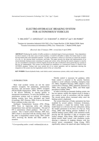
Figure 1. The braking system design.
3. ELECTRO-HYDRAULIC BRAKING SYSTEM FOR AUTONOMOUS VEHICLES
2. BRAKING SYSTEMS DESIGNED proportional pilot, being even in the worst case at most
10 ms.
The AUTOPIA C3 Pluriel was already automated, Following the design of the hydraulic and electronic
but with only the steering wheel and accelerator components, the system needs to be plugged into the
controlled. Speed control was good as long as sudden existing car braking system. To this end, a shuttle valve
changes in speed were not required. Thus, the necessary is installed to form the junction between the two
next step was to design and implement a braking system. systems. This valve permits flow from either of two
This system would have to be capable of operating as a inlet ports to a common outlet. A free-floating metal
minimum at the AUTOPIA control sampling rate, which ball shuttles back-and-forth according to the relative
was set by the GPS at 5 Hz. pressure at the two inlets. Flow from the higher pressure
The main prerequisite was to obtain a brake by wire inlet through the valve moves the ball to close the
system in coexistence with the original braking system. opposite inlet. This valve is thus responsible for the
The solution decided on was to design a hydraulic switching between the two braking systems. The model
system equipped with electronic components to permit selected was the Hawe Hydraulic WV 6-S. It was
handling by computer generated signals through an chosen because the smallness of the flow through a
input/output device. braking system permits one to select the valve of least
Before proceeding with the design, it was necessary diameter which also has the smallest floating ball, thus
to determine the maximum braking pressure in order to minimizing the switching time. The valve is mounted
avoid excessive system stress. This datum was so that the ball under gravity maintains the standard
determined experimentally by means of a manometer. A braking system open when the electro-hydraulic system
wheel was removed, and a manometer was connected in is switched off.
lieu of the brake shoe. A pressure of 160 bars was The shuttle valve introduces a delay associated with
measured when the brake pedal was completely pressed the movement of the metal ball between the two inlets.
down. The delay time calculated for the selected model was
The hydraulic system consists of a one-litre capacity less than 1 ms for the minimum pressure of 10 bars.
brake fluid tank that includes a gear pump and coupling The connection between the shuttle valve and the
to a 350-watt, 12-volt supply, dc motor. A pressure electro-hydraulic braking system is through the output
limiter tube whose value is fixed at 160 bars is added in of the spool directional valve which is connected to one
order to protect the car elements involved in the braking of the inputs of the shuttle valve.
process. This system permits one to obtain the Figure 1 shows the design scheme of the braking
maximum pressure that the original braking system is system. The Citroën C3 Pluriel includes a safety system
able to apply on the wheels. Electronic components are based on a duplicated braking signal. Therefore, two
needed to regulate this pressure as required by the shuttle valves are used to switch between the
computer. To this end, two electronic components are conventional and the electro-hydraulic braking systems.
included. One is used to regulate the pressure between 0 The outputs of the two shuttle valves are connected to
and the maximum value, and the other to transmit this the ABS inputs. Finally, the ABS performs the
pressure from the pump to the wheels. In order to distribution of the braking.
regulate the flow of the pressure, an electro-proportional Figure 2 shows the shuttle valves assembled in the
pilot is installed with a nominal pressure between 12 car. One of the goals was to maintain the original brake
and 250 bars. The control voltage varies between 0 and circuit unchanged. For this reason, the shuttle valves are
10 volts. The electro-proportional pilot yields a non-null installed as closely as possible to the ABS. One can see
minimum pressure, and hence will always exert some in the figure the two inputs of each shuttle valve. The
small pressure on the wheels. The second element, a lower input is connected to the automatic electro-
spool directional valve, is used to resolve this problem. hydraulic braking system, and the upper input to the
It is normally open, and is only closed when the original system.
proportional pilot is actuated. The system described is designed to operate built into
These two elements cause delays that cannot be the AUTOPIA control system which has a sampling
disregarded if good behaviour of the system is desired. period of 200 ms. The design constraints of the braking
At the first sampling period after brake actuation is system were that it should not introduce significant
requested, a signal is sent simultaneously to both valves, delays. The greatest delay appears on initiation of the
and the actual delay corresponds to that of the slower automatic brake, and is the sum of the shuttle valve and
element – the spool directional valve whose switching the spool directional valve delays, the result being
time is about 30 ms. For subsequent sampling periods, 31 ms. In the following sampling periods, there only
the spool directional valve is already closed and the exist the delays in the electro-proportional pilot, with
delay corresponds only to that of the electro- values less than 10 ms.
4. V. MILANÉS et al.
battery through the dc motor's accessible terminals so
that it can be switched on by the same manual switch
and at the same time as the dc motor.
Finally, the pump includes two outputs. One is
divided into two and connected to the shuttle valves.
The other is installed to measure the pressure with a
manometer. The manual switch installed in the
dashboard activates a relay that connects the power
supply to the dc motor. A DIN rail is used to fix the
CAN bus module and the relay. Figure 3 shows the
distribution of each element under the trunk.
Several problems had to be solved. Initially, the fluid
tank of the pump was closed by means of a vent plug,
and the system worked well. But when the car was
stationary, the brake fluid passed little by little from the
Figure 2. Locations of the shuttle valves. original brake fluid tank of the car into the fluid tank of
the pump. This was due to the fundamental hydrostatics:
The automatic system operates as follows. It is turned the place where we had put the pump was lower than
on by means of a manual switch installed in the the fluid brake tank of the car. Therefore, the brake fluid
dashboard. The dc motor is started by means of a relay passed through the shuttle valves and the tank
that is activated when the switch is turned on. As long overflowed through the vent plug. The solution to this
as the spool directional valve is open, a 10-bar pressure problem was to fill the tank to the limit and use an
appears through the electro-proportional pilot and the impervious plug to avoid overflow. This posed a new
flow is driven back to the tank. When the spool problem: when the pump was disconnected, there
directional valve is closed, the pressure is applied to the remained a small pressure in the circuit. This pressure
shuttle valves and pushes their metal balls to the upper increased and exerted a force on the brake shoes, and
position to allow the brake fluid to circulate towards the eventually the car became permanently braked. The
brake shoes. From this moment onwards, the braking solution adopted was to communicate the two tanks by
can be regulated by means of the electro-proportional means of a tube. A perforation was made in the
pilot. impervious plug to allow a tube to be inserted into the
tank of the pump. Another perforation in the vent plug
3. IMPLEMENTATION OF THE BRAKING of the original tank was made to communicate the two
SYSTEM tanks. In that way, the necessary air vent for the pump
was supplied by the original tank. The tank of the pump
After constructing the braking system, we needed to was filled to the limit, and the overflow produced
decide on a place within the car in which to place it. The returned to the circuit by means of the tube. The tube
choice was to install the system under the trunk in the installed in the pump can be seen in Figure 3.
place reserved for the spare wheel. The compact design
allows the use of this location where the pump is
protected against collisions, and damage that may be
caused by the driver is avoided. The spare wheel is now
located at the same place under the chassis.
The pump dc motor is connected to a 12-volt
auxiliary battery. This battery is fixed to the chassis by
means of an elastic strap, and can be recharged with a
socket in the lateral wall of the car that is directly
connected to the car battery.
The auxiliary battery feeds another device as well as
the dc motor. A CAN bus module is used to control the
spool directional valve and the electro-proportional pilot
by means of an on-board PC. This module consists of a
6-ampere relay output that is used to feed the spool
directional valve, and a computer controlled analogue Figure 3. Location of the electro-hydraulic braking
output that is connected to the electro-proportional pilot. system.
The CAN module voltage supply is connected to the
5. ELECTRO-HYDRAULIC BRAKING SYSTEM FOR AUTONOMOUS VEHICLES
stopped so that different responses can be studied. The
top plot of the figure corresponds to no braking force
being applied, and shows a slow decrease in speed. At
around second 24, a change in slope can be observed
that is due to the reduction in the gearbox. The middle
plot shows the speed reduction when the human driver
executes “soft” braking. In this case, around fifty metres
are needed to stop the car. The idea is to try to identify
habitual driver action while the driver is attentive to
traffic. The bottom plot illustrates a case of “hard”
Figure 4. Private driving circuit at the IAI facilities. braking, the idea being to identify an unexpected
incident on the road requiring hard braking.
4. BRAKING SYSTEM TEST Figure 6 shows the results of automatic braking with
different tests carried out in order to compare their
results with those of the manual response shown in
The system was implemented in a Citroën C3 Pluriel
Figure 5. As in the previous tests, the first part of each
car. Several tests were performed to evaluate its
trial was done in automatic mode. The experiments
behaviour in different situations, with very good results.
were carried out by activating the electro-proportional
Figure 4 is a map of the private driving circuit at the
pilot at different sets of values.
IAI facilities. This circuit represents an inner-city area,
The electro-hydraulic pump is limited to 160 bars,
with a combination of straight road segments, curves,
and when it is working at this pressure the electro-
and 90° intersections. The longest straight-road
proportional pilot is totally open (100%). Figure 7
segment was used to carry out the tests since their main
shows the experimentally determined relationship
purpose was to observe the behaviour of the new
between the opening percentage of the electro-
braking system.
proportional pilot and the pressure supplied by the pump.
At each end of this stretch there are traffic
One observes that the relationship between the two
roundabouts, and the car is initially located at one of
variables is close to linear. The system designed thus
them. The car is accelerated until the braking point to a
exerts a pressure on the wheels that is linearly related to
speed of 46 kilometres per hour. The distance covered is
the control variable which is generated with an analogue
around one hundred metres. During this time, the car is
output whose value ranges from 0 to 10 volts.
driven automatically, and the speed reference is
The pressure percentages, i.e., openings of the
introduced by means of software commands.
electro-proportional pilot, used in the tests were the
When the car reaches the braking point (Figure 4), a
following: 10%, corresponding to very soft braking;
new speed reference of zero kilometres per hour is
20%, with a response similar to that of the manual soft
assigned. From this moment on, only friction forces are
braking but with a more uniform decrease in speed;
acting on the car, and the braking force can be evaluated.
30%, where the car's behaviour is comparable to that of
First, manual tests were performed to determine the
the manual hard braking; and finally 40%,
car's response to braking (Figure 5). The plots show the
corresponding to very hard braking to simulate an
variation of speed with time along the road. The car
emergency stop. The braking in this last case is stronger
accelerates during the first 13 seconds in automatic
that what a human driver would consider “hard” braking.
mode. The changes in slope in this interval are due to
Values greater than 40% were not used because they
the automatic gearbox. Then the acceleration is
were considered uncomfortable for passengers.
Figure 5. Manual braking tests. Figure 6. Automatic braking tests.
6. V. MILANÉS et al.
Figure 7. Relationship between the electro-proportional
pilot and the pressure.
The results showed the electro-hydraulic braking
system to present good behaviour, and even to have a
better response than the manual system thanks to the
linearization of the decrease in speed due to the constant
braking reference.
5. AUTOMATIC CONTROL OF BRAKING
Figure 8. Targets for accelerator and brake on a track.
After the implementation and testing of the system,
controllers. One observes that the brake signal is
the following step was to incorporate it into the
greatest when a large decrease in speed is requested.
automatic vehicle. The AUTOPIA project's Citröen C3
The variations in speed shown in the plot when the
Pluriel was already controlled longitudinally and
target speed is reached were small, about ±2.5 km/h,
laterally, but only the accelerator was used to control the
and imperceptible to the car's occupants.
speed so that the behaviour was still not sufficiently
satisfactory.
Optimal longitudinal control of the vehicle requires
cooperation between throttle and brake pedal. The 6. CONCLUSIONS
AUTOPIA group had already implemented a braking
system in two Citroën Berlingo vans in which the brake This paper has described the design and
pedal was controlled by means of a motor that moved implementation of an electro-hydraulic braking system.
the pedal via a pulley. Since this method was too error- A pump governed by means of three valves was
prone, the present novel way of controlling the brake designed to perform the control. One of these valves
was developed. However, the fuzzy-logic based was used to limit the pressure, another to allow or avoid
controllers used in the Citroën Berlingo vans (Naranjo, pressure circulation, and the third was an electro-
2006) were easily transferred to the Citroën C3 Pluriel proportional pilot to control the pressure of the brake
because they yield normalized output values between 0 fluid.
and 1, where 0 means no braking at all and 1 maximum Some problems arose associated with the brake fluid
pull. pressure. They were resolved using a tube to
The automatic system's behaviour shown in Figure 6 communicate the tank of the pump and the car's brake
allows one to evaluate the braking response to different fluid tank. A CAN bus module was used to perform the
target values and match it with that of the human driver control of the system by means of software commands,
(Figure 5). Thus, the upper limit of the fuzzy controller and a relay connected to a manual switch in the
was set to 40% of the maximum pressure of the pump. dashboard was implemented to start the system.
Figure 8 shows the data of an automatic driving Various tests of the designed system were carried out
experiment around the private circuit at the IAI facility. to verify its correct operation, yielding good results.
The curves in the circuit force the changes in speed. The Experimental trials were conducted to determine how
upper plot shows the comparison between the real speed the system behaves in imitating driver actions in
and the target speed for 100 seconds, and the lower plot different situations. The automatic system was shown to
the output values of the brake and throttle fuzzy achieve linear reductions in speed in stopping the car –
7. ELECTRO-HYDRAULIC BRAKING SYSTEM FOR AUTONOMOUS VEHICLES
one of the objectives in providing comfortable and safe Li Z., Wang K., Li L., Wang F (2006). A Review on
braking. Vision-Based Pedestrian Detection for Intelligent
The electro-hydraulic braking system was installed in Vehicles. IEEE International Conference on
the AUTOPIA automatic control car, and the Vehicular Electronics and Safety 57-62.
experiments performed showed the behaviour to be Liang H., Chong K., No T., Yi S (2003). Vehicle
good, with good speed control, and good subjective Longitudinal Brake Control Using Variable
rating of the system by the car's passengers. Parameter Sliding Control. Control Engineering
The results strongly suggest that an automatic Practice 11, 403-411.
collision-avoidance system can be used if an electro- Lignon S., Sinou J-J., Jézéquel L (2006). Stability
hydraulic braking system is allowed to work at 100% of analysis and μ-synthesis control of brake systems.
its strength. This would thus offer a possible solution Journal of Sound and Vibration 1073-1087.
for the reduction of car accidents on roads as a Maciuca D., Hedrick J.K (1997). Nonsmooth Dynamic
complement to obstacle detection systems. Surface Control of Non-Lipschitz Nonlinear Systems
with Application to Brake Control. Proceedings of
ACKNOWLEDGEMENT− This work was carried out with the 1997 IEEE International Conference on Control
the support of TRANSITO (TRA2008-06602-C03-01) project Applications 711-716.
from Plan Nacional, GUIADE (P 9/08) project from Maciuca D., Hedrick J.K (1998). Nonsmooth Estimation
Ministerio de Fomento and MARTA project (CENIT- and Adaptative Control with Application to
20072006).
Automotive Brake Torque. Proceedings of the
American Control Conference 2253-2257.
REFERENCES Naranjo J.E., González C., García R., de Pedro T (2006).
ACC+Stop&go maneuvers with throttle and brake
Bu F., Tan H. (2007). Pneumatic Brake Control for fuzzy control. IEEE Trans. on Intelligent
Precision Stopping of Heavy-Duty Vehicles. IEEE Transportation Systems 7,2, 213-225.
Trans. on Control System Technology 15, 1, 53-64. Naranjo J.E., González C., García R., de Pedro T.,
Celentano G., Iervolino R., Porreca S., Fontana V. Haber, R.E (2005). Power-steering control
(2003). Car Brake System Modeling for Longitudinal architecture for automatic driving. IEEE Trans. on
Control Design. IEEE Conference on Control Intelligent Transportation Systems 6, 4, 406-415.
Applications – Proceedings; 1 25-30. Park E.J., Stoikov D., Falcao L., Suleman A (2006). A
Collado J.M., Hilario C., de la Escalera A., Armingol performance Evaluation of an Automotive
J.M (2004). Model Based Vehicle Detection for Magnetorheological Brake Design with a Sliding
Intelligent Vehicles. IEEE Intelligent Vehicles Mode Controller. Mechatronics 16, 405-416.
Symposium 572-577. Petersen A., Barrett R., Morrison S. (2006). Driver-
Cummings P., Grossman D.C (2007). Antilock Brakes Training and Emergency Brake Performance in Cars
and the Risk of Driver Injury in a Crash: A Case- with Antilock Braking Systems. Safety Science 44,
Control Study. Accident Analysis &Prevention 39, 905-917.
995-10. Ryu J. H., Kim C. S., Lee S. H., Lee M. H. (2007) H∞
Gerdes J.C., Hedrick J.K (1997). Vehicle Speed and Lateral Control of an Autonomous Vehicle using the
Spacing Control Via Coordinated Throttle and Brake RTK-DGPS. International Journal of Automotive
Actuation. Control Eng. Practice 5, 11, 1607-1614. Technology 8, 5, 583-591.
Hong D., Yoon P., Kang H., Hwang I., Huh K (2006). Song B., Hedrick J. K (2004). Design and Experimental
Wheel Slip Control Systems Utilizing the Estimated Implementation of Longitudinal Control for
Tire Force. Proceedings of the 2006 American Automated Transit Buses. Proceeding of the 2004
Control Conference 5873-5878. American Control Conference 2751-2756.
Jung S. P., Jun K. J, Park T. WYoon., J. H. (2008). Song G., Jiang M., Zhao G (2006). The Research of an
Development Of The Brake System Design Program Intelligent Braking Control System. 7th IEEE
For A Vehicle, International Journal of Automotive International Conference on Computer Aided
Technology 9, 1, 45-51. Industrial Design and Conceptual Design .
Kang Y., Hedrick J. K. (2004). Emergency Braking Song J (2005). Performance Evaluation of a Hybrid
Control Of A Platoon Using String Stable Controller. Electric Brake System with a Sliding Mode
International Journal of Automotive Technology; 5, 2, Controller. Mechatronics 15, 339-358.
89-94. Wang F., Herget C., Zeng D (2005). Guest Editorial
Kim H., Dickerson J., Kosko B (1996). Fuzzy Throttle Developing and Improving Transportation Systems:
and Brake Control for Platoons of Smart Cars. Fuzzy The Structure and Operation of IEEE Intelligent
Sets and Systems 84, 209-234.
8. V. MILANÉS et al.
Transportation System Society. IEEE Trans. on World Health Organization (2004). World Report on
Intelligent Transportation System, 6, 3, 261-264. Road Traffic Injury Prevention.
Wang J., Schroedl S., Mezger K., Ortloff R., Joos A., Yi J., Alvarez L., Horowitz R (2002). Adaptative
Passegger T (2005). “Lane Keeping Based on Emergency Braking Control with Underestimation of
Location Technology”. IEEE Trans. on Intelligent Friction Coefficient. IEEE Trans. on Control Systems
Transportation Systems 6,3, 351-356. Technology 10, 3, 381-392.