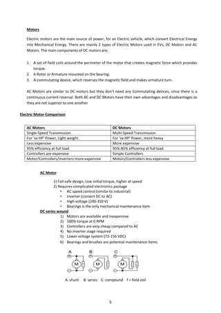
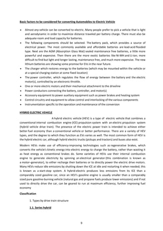
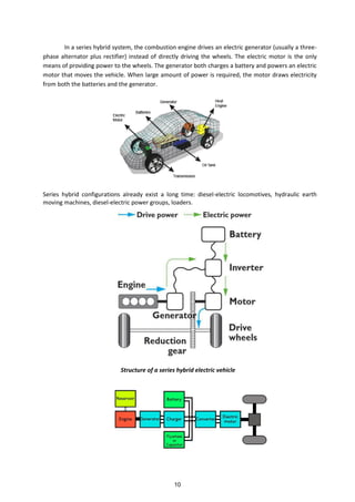
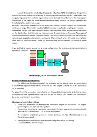
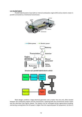
This document serves as a comprehensive guide on modern automotive technology, focusing on electric and hybrid vehicles for B.Tech mechanical engineering students. It covers various topics including electric vehicle components, fuel cells, evolving automotive systems, emission standards, and the benefits of electric cars over internal combustion engines. The text emphasizes the importance of transitioning to cleaner energy sources and the technical aspects involved in converting conventional vehicles to electric or hybrid formats.


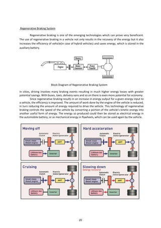
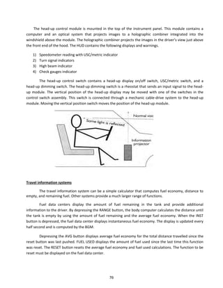
![Regenerative braking refers to a process in which a portion of the kinetic energy of the vehicle
is stored by a short term storage system. Energy normally dissipated in the brakes is directed by a
power transmission system to the auxiliary battery during deceleration. The energy that is stored by
the vehicle is converted back into kinetic energy and used whenever the vehicle is to be accelerated.
The magnitude of the portion available for energy storage varies according to the type of storage,
drive train efficiency, drive cycle and inertia weight. The effect of regenerative brakes is less at lower
speeds as compared to that at higher speeds of vehicle. So the friction brakes are needed in a
situation of regenerative brake failure, to stop the vehicle completely
Working of Regenerative Braking using Electric Motor
The working of the regenerative braking system depends upon the working principle of an
electric motor, which is the important component of the system. Generally the electric motor, is
actuated when electric current is passed through it. But, when some external force is used to actuate
the motor (that is during the braking process) then it behaves as a generator and generates electricity.
That is, whenever a motor is run in one direction the electric energy gets converted into mechanical
energy, which is used to accelerate the vehicle and whenever the motor is run in opposite direction it
functions as a generator, which converts mechanical energy into electrical
energy. This makes it possible to employ the rotational force of the driving axle to turn the electric
motors, thus regenerating electric energy for storage in the battery and simultaneously slowing the
car with the regenerative resistance of the electric motors [2]. This electricity is then used for
recharging the battery
Advantages
Better fuel economy.
Reduced CO2 emissions.
Approximately 30% saving in fuel consumption.
The lower operating and environment cost of the vehicle with regenerative braking system.
Increase of overall energy efficiency of a vehicle
Increases vehicle range
Cuts down on pollution related to electricity generation
Increases the lifespan of friction braking systems
Less use of traditional mechanical brakes leads to less wear over time
Disadvantages
Added complexity of brake control system
Only works for wheels connected to motors
Most vehicle operation is done in 2WD
Friction brakes are still necessary
Safety
Motor braking power decreases as the kinetic energy of the vehicle decreases
21](https://image.slidesharecdn.com/newmat-150925151252-lva1-app6891/85/MODERN-AUTOMOTIVE-TECHNOLOGY-21-320.jpg)