Downloaded 488 times


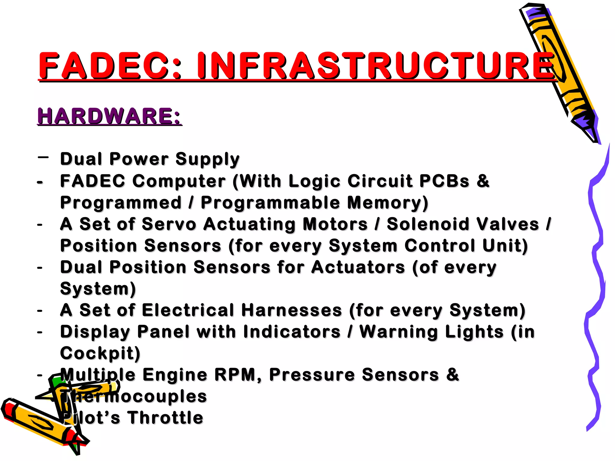
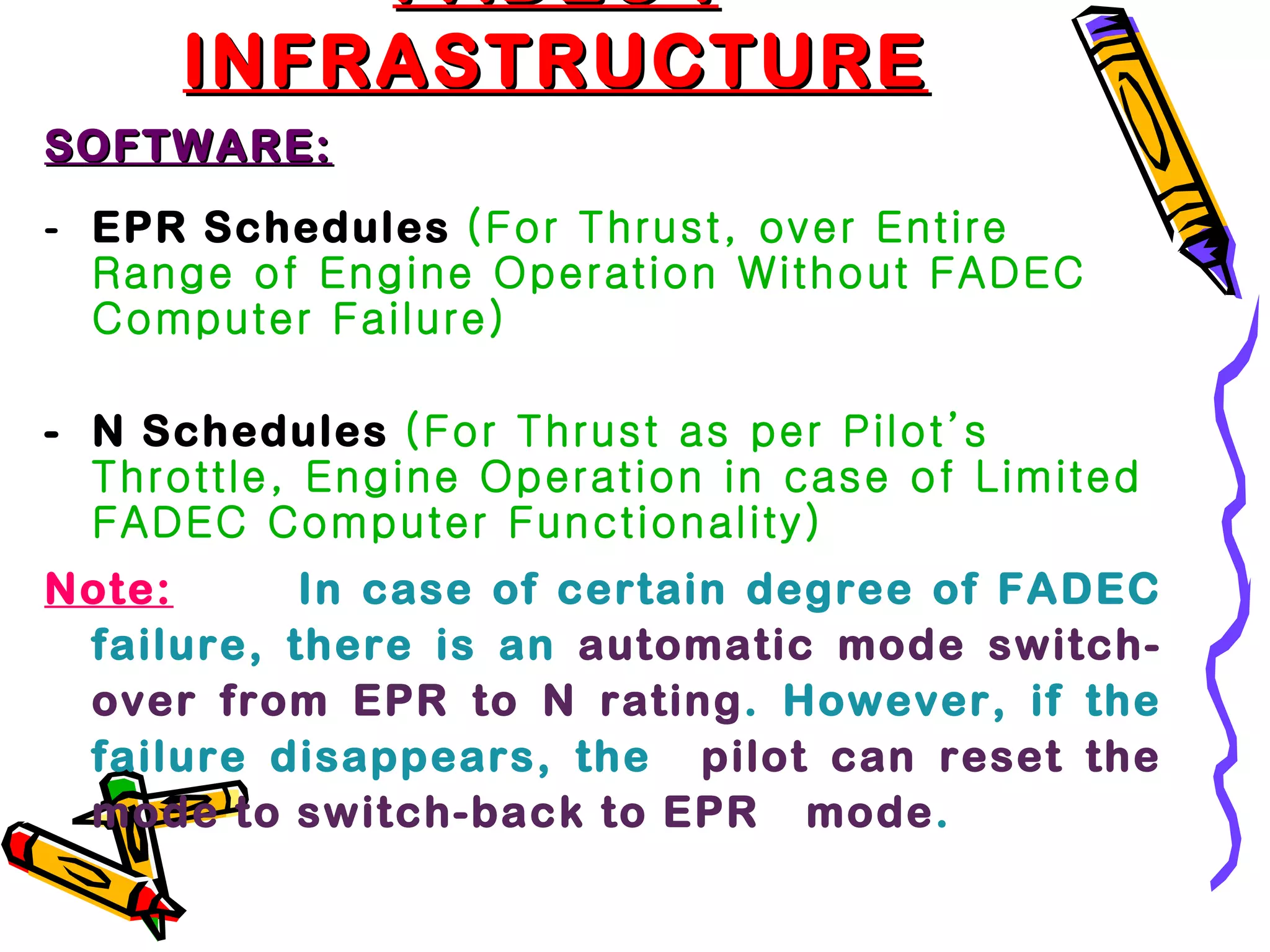

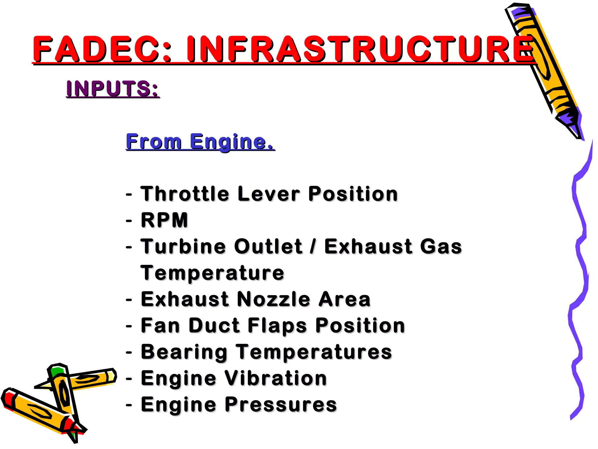


FADEC, or Full Authority Digital Engine Control, is a digital electronic control system that can autonomously control all aspects of aircraft engine performance. It receives data from multiple sensors, processes the data using control laws 70 times per second, and computes appropriate settings for parameters like fuel flow. FADEC allows for optimized and precise engine control, lowering pilot workload and improving reliability and efficiency.