Download as PDF, PPTX


![Thixothropyandanti-thixc›tr»py
600-
300 -
200 -
Shearing stress
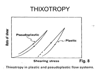
fig,20-4. Thixovopy in plastic and pseudoplsstic flow systems.
100 -
p gg jgq j$q 200 250 30D 35D
shaming stress (dynes/ C f¥3
)
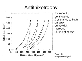
Fig, 20-é. Rheogram of magnesia jyjggpjg g|j OW]Ij g BnñthiXOtf0 IC
behavior. ThB fTl8terial s shesred at rapeeted increasing andthefl
decreasing rates of shear. At 5t6ge d , furthef cycling no long6£
increased the consistency, and the upcurves anddowncurVBS C0In-
cided.lFromC.W.thong,S.P,Eriksen,andJ.W.tflt0Sl0/,J.Am.
Pharm.Assoc.SCi.E4,49,54?,1960,Withpermission.)](https://image.slidesharecdn.com/2-240129055953-84687788/85/2-RHEOLOGY-pdf-52-320.jpg)
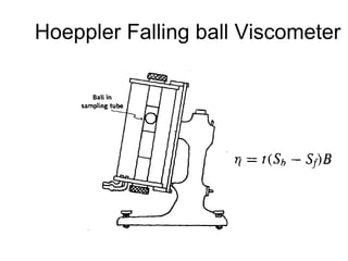
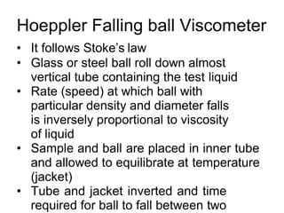
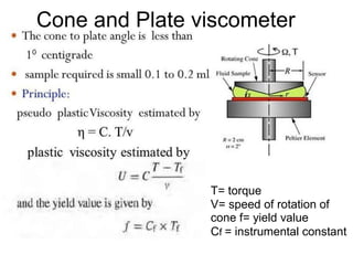
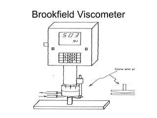
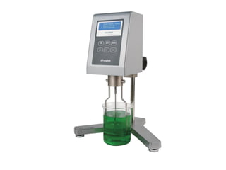
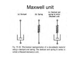

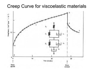
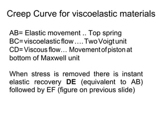
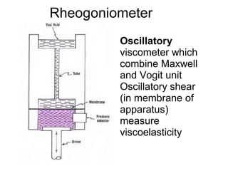


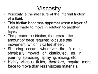
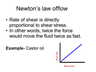
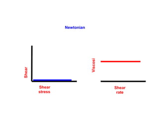
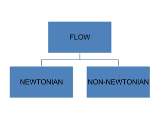
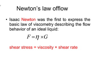
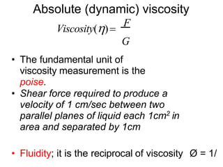
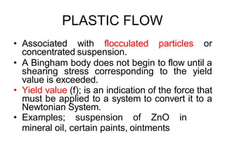
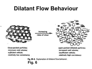
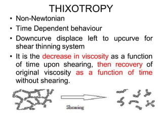
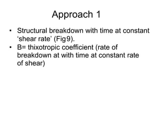
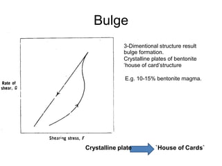
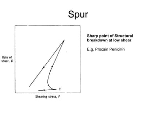
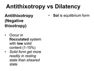
This document discusses rheology and viscosity measurement techniques. It covers key topics like: 1) Newtonian and non-Newtonian flow, including plastic, pseudoplastic and dilatant systems. 2) Measurement of viscosity using viscometers like capillary, falling sphere and rotational viscometers. 3) Phenomena like thixotropy, antithixotropy and their significance in formulations. The document provides an overview of important rheological concepts and methods to characterize the flow behavior and viscosity of formulations.


