Downloaded 116 times
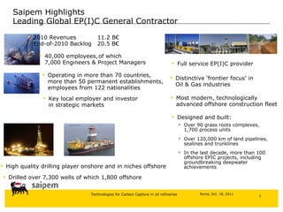
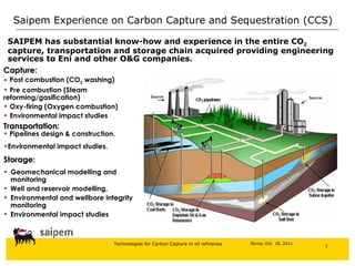
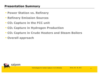
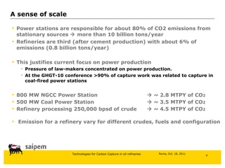
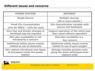
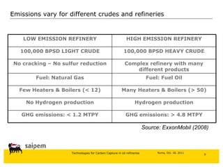
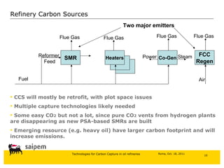
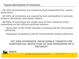
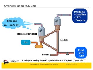
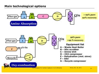
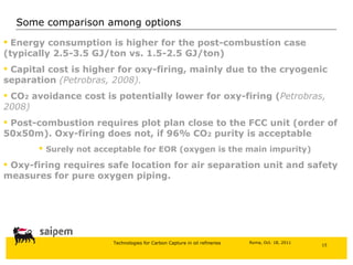
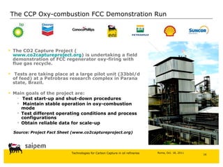
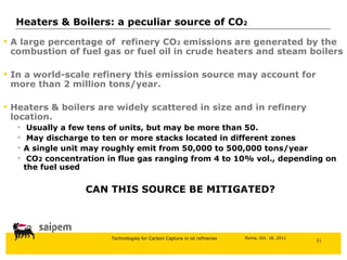
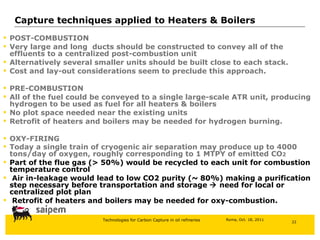
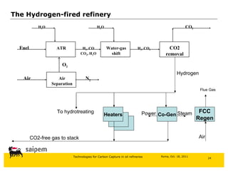
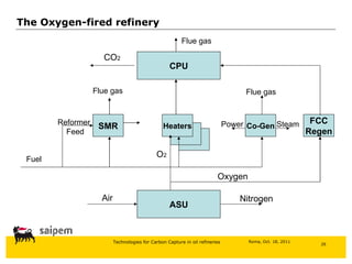
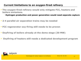

Saipem has experience providing engineering services for carbon capture, transportation, and storage projects for oil and gas companies. This includes designing pipelines, conducting environmental impact studies, and modeling wells and reservoirs. The document then discusses differences between capturing carbon from power stations versus refineries, sources of emissions in refineries, and options for capturing carbon from fluid catalytic cracking units, hydrogen production plants, and heaters/boilers in refineries. It concludes by outlining two overall approaches - converting a refinery to run on hydrogen or using oxygen combustion.


