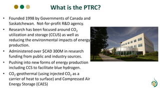
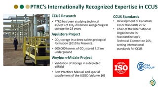
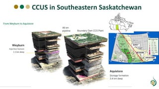
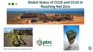
Norm Sacuta, Director of Communications
Brittney Musleh, Business Development Officer
Introduction to Carbon Capture and Storage
Our Presenters
Norm Sacuta
MA, MFA.
Director of Communications,
Petroleum Technology Research
Centre
Brittney Musleh
BBA, Cert. Non-Profit Lifecycle Consulting
Business Development Officer,
Petroleum Technology Research Centre
What is the PTRC?
• Founded 1998 by Governments of Canada and
Saskatchewan. Not-for-profit R&D agency.
• Research has been focused around CO2
utilization and storage (CCUS) as well as
reducing the environmental impacts of energy
production.
• Administered over $CAD 300M in research
funding from public and industry sources.
• Pushing into new forms of energy production
including CCS to facilitate blue hydrogen.
• CO2-geothermal (using injected CO2 as a
carrier of heat to surface) and Compressed Air
Energy Storage (CAES)
PTRC’s Internationally Recognized Expertise in CCUS
CCUS Research
• PTRC has been studying technical
aspects of CO2 utilization and geological
storage for 23 years
Aquistore Project
• CO2 storage in a deep saline geological
formation (2010 to Present).
• 600,000 tonnes of CO2 stored 3.2 km
underground
Weyburn-Midale Project
• Validation of storage in a depleted
oilfield
• Best Practices Manual and special
supplement of the IJGGC (Volume 16)
CCUS Standards
• Development of Canadian
CCUS Standards 2012
• Chair of the International
Organization for
Standardization’s
Technical Committee 265,
setting international
standards for CCUS
CCUS in Southeastern Saskatchewan
Course Outline
• Global state of CCS and the role of CCS in
reaching net-zero emissions
• Overview of capture technologies
• Overview of transport options
• Risk assessment and storage site
characterization
• CO2-enhanced oil recovery
• Measuring, monitoring and verifying CO2
storage
• Public and stakeholder engagement
• Closure and post closure of CO2 storage sites
Global Status of CCUS and CCUS in
Reaching Net Zero
Gorgon (Australia); Weyburn and Aquistore (Canada)
Role of CCS in Reaching Net-Zero
https://www.lse.ac.uk/granthaminstitute/explainers/what-technology-do-we-need-to-cut-carbon-emissions/
Operational CCUS Projects by Storage Type
0
5
10
15
20
Asia-Pacific USA Canada Europe S America Middle East
Total capture rates Mt/year across all projects >0.5Mt/year
Dedicated Associated
Operational CCUS Projects by Capture Source
0
5
10
15
Asia-Pacific USA Canada Europe S America Middle East
Total capture rates Mt/year across all projects >0.5Mt/year
Gas Processing Fertilizer Coal gasification Power Iron and Steel Steam methane reformer Ethanol
Operational Projects – Americas
Project Capture type Year started Nominal annual rate
Mt/yr
Storage type
Great Plains, USA Coal gasifier 2000 3.0 Associated
Shute Creek, USA Gas processing 2010 7.0 Associated
Illinois Industrial, USA Ethanol 2017 1.0 Dedicated
Air Products, USA Steam methane
reformer
2013 1.0 Associated
Century Plant, USA Gas processing 2010 5.0 Associated
Boundary Dam, Canada Coal fired power
Post Combustion
2014 1.0 Associated plus
Dedicated
Shell Quest, Canada Steam methane
reformer
2015 1.0 Dedicated
Alberta Carbon Trunk
Line, Canada
Fertilizer plant,
refinery, others
2020 1.3 Associated
Santos Basin, Brazil Gas processing 2008 8.7 Associated
Operational Projects – Rest of World
Project Capture type Year started Nominal annual rate
Mt/yr
Storage type
Sleipner, Norway Gas processing 1996 0.9 Dedicated
Gorgon, Australia Gas processing 2019 3.4 Dedicated
Qilu-Shengli, China Fertilizer plant 2022 1.0 Associated
Qatar LNG Gas processing 2019 2.1 Associated
OTHER NOTABLE PROJECTS:
Utmanyah, Saudi
Arabia
Gas processing 2015 0.8 Associated
Abu Dhabi Iron and steel 2016 0.8 Associated
Snohvit, Norway Gas processing 2008 0.7 Dedicated
U.S. financial Incentives Driving Deployment
Storage Type Operational
capture rate in
U.S. 2023
(Mt/yr)
Predicted 2030
capture rate in
U.S. 2030
(Mt/yr)
Dedicated 1 90
Associated 20 30
Unspecified 40
TOTAL 21 160
• Increase in operational capacity
has, to date, been gradual
• Predicted surge in project
numbers driven by 45Q tax
legislation
• Note:
• Numbers estimated to 1
significant figure
• 2030 numbers based on public
announcements
Scale of Deployment Required
40 large-scale CCS projects -
combined capture capacity of
approximately 71 Mtpa*:
• 22 projects in operation or
construction (40 Mtpa)
• 6 projects in advanced
planning (6 Mtpa)
• 12 projects in earlier stages of
planning (25 Mtpa)
OECD
Non-OECD
~4,000 Mtpa of CO2
captured by CCS by 2040
(IEA 450 Scenario)**
40 Mtpa
Global Status of CCS
(Global CCS Institute, 2017)
*Mtpa = million tonnes per annum
**Source: IEA, Energy Technology Perspectives (2016).
Research Priorities
• Capture research trends
• Gas-fired power
generation
• Industrial sources
• Direct Air Capture
• Hybrid technology systems
• Transport research
• limited need as technology
is essentially proven
• Storage research priorities are
changing
• Some fundamental, pore-scale
research is ongoing
• Focus shifting to applied field
research to support project
Recycle CO2 pipe at
Weyburn facility
Current and Emerging Technologies for
Carbon Capture
Special thanks to Dr. Hussam Ibrahim of
University of Regina’s CETRI
Introduction
There are currently three main types
of capture technologies:
• Pre-combustion
• Post-combustion
• Oxyfuel combustion
Pre combustion: Kemper County Energy Facility
Post combustion: Boundary Dam SaskPower
Left: Allam-Fetvedt Cycle demonstration plant
(Oxy-combustion) in La Porte, Texas, NET POWER
Pre-Combustion Capture
• Pre-combustion capture is often
used in integrated gasification
combined cycle (IGCC) power
plants.
• In this process, coal or other fossil
fuels are converted into a gas
mixture of hydrogen and carbon
monoxide, known as syngas.
• The syngas is then burned to
generate electricity, while the
carbon dioxide is separated and
captured.
Post Combustion Capture
• Post-combustion capture is
the most widely used
capture technology, as it can
be retrofitted onto existing
power plants.
• This process involves
capturing carbon dioxide
from the flue gas after the
fuel has been burned,
typically using solvents or
membranes.
Shell Consolv Process Figure from Shell
Oxyfuel Combustion
• Oxyfuel combustion involves burning fuel in pure oxygen
instead of air, which produces a flue gas consisting mainly of
carbon dioxide and water vapor.
• This makes it easier to capture the carbon dioxide, as there
are fewer other gases present.
Emerging Capture Technologies
• There are also several emerging
capture technologies that are still in
the research and development stage
• catalyst-aided novel solvents-based
capture, which uses catalytically
enhanced novel solvent blends to
selectively separate carbon dioxide
from other gases.
• membrane-based capture and direct
air capture, which involves capturing
CO2 directly from the atmosphere
using special filters or chemicals.
• DAC: Direct Air Capture
Direct Air Capture Schematic
CO2 Transportation Options
Transport Types
• Pipelines = predominant
established option for long
distance transportation
• Increasing U.S. interest in rail
• Tankers (both short and long
distance)
• Trucks (short distance transport of
smaller quantities)
• Ship for offshore e.g. Northern
Lights project, Norway (used for
intercontinental transport of CO2)
Photo: Aquistore CCS Project, Saskatchewan, Canada
Ship Transport of CO2
https://norlights.com/
• In Europe on shore
storage has been banned
in many countries due to
public perception issues
• Ship transport using
tankers similar to natural
gas transport
• Equinor already has two
offshore projects (Sleipner
and Snohvit) but these are
platform based for CO2
and not ship based)
Land Transport of CO2
Photo from: TOMCO Systems
https://tomcosystems.com/product/co2-transportation/
• Land transportation of CO2 via
tanker trucks is most often
associated with pilot injection
projects for EOR or small utilization
efforts like fertilizer or cement
manufacturing
• Most utilization efforts outside of
EOR require smaller amounts of
CO2. Pipeline access would be
expensive (unless the pipelines are
near to these industrial uses)
• CO2 sources would need to have
specially fitted compression and
loading stations for ground
transport
Pipelines
Three primary types of pipelines for CO2
• Gathering line
• Trunk line
• Distribution line
Integrity Challenges with CO2 pipeline
• Corrosion both external and internal
• Water accumulation
• CO2 and H2O put into high pressure,
more CO2 can dissolve in the water (
soda)
• CO2+H2O H2CO3 carbonic acid
• Carbonic acid is corrosive , PH goes
down
Pipelines
Requirements (EPA standards) :
• Dehydrate the CO2 (dry CO2 consisting less than 50ppm
of water)
• Construct or soak CO2 pipeline with non-corrodible
materials such as polymers and fiber glass
• Water dropout traps – collect and drain excess fluids
• Pipeline exposed to the surface may be wrapped in
insulation to protect against or minimize phase change
and pressure issues resulting from changes in
atmospheric conditions
Can we use existing hydrocarbon pipelines?
• Integrity challenges
• Internal corrosion
• Cracking
• Multiple feeders depending on sources
• CO2 needs to be transported at 700 PSI higher
than natural gas therefore CO2 pipeline walls have
to be thicker than other types of pipeline
Pipelines: Repurposing Existing Infrastructure
Best approach to a safe conversion of
existing pipeline to CO2
• Good understanding of integrity of pipeline is a
must
• Operate CO2 in a dense phase
• Understand historical services to deploy proper
inspection strategies
• Pipeline material and fracture toughness
• Monitor metal loss and corrosion and fracture
Risk Management for CO2 Storage
Purpose of Risk Management
The purpose of risk management is to ensure that
the risk scenarios involved in CO2 storage project
are effectively managed and reduced to an
acceptable level.
Risk Management for CO2 Storage
Risk Management
(Containment and
Storage Performance)
• Risk Assessment
• Risk Identification, Analysis, and
Evaluation
• Risk Mitigation
• Treating, Monitoring, and
Reviewing/Reevaluating
Project Values & Objectives
• Articulate the objectives of the project and define the scope,
conditions, and criteria for the process for risk management.
• Identify the appropriate elements of concern for the project.
• Often defined by the values of the organization
Risk Evaluation Criteria
Identify the appropriate elements of concern for the project and establish risk
evaluation criteria for each element of concern based on the scope and objectives
of the project.
Evaluation Criteria
Criteria against which
each risk is evaluated
and distinguished as
acceptable, tolerable, or
unacceptable.
• Acceptable Risk
• Tolerable Risk
• Unacceptable Risk
The Risk Assessment Workshop
• Gathering experts to debate risks
• Structured around predetermined
risk scenarios (FEPs)
• Experts are ranked and represent
best the different aspects of the
project
• Timing of workshop is key in the
overall project workflow
• How much data is required vs. how
much data do you have
Ranking Risks in Risk Matrix
Risk Analysis & Evaluation
Features, Events and Processes (FEPS)
• Risk scenarios for each identified
threat
• Likelihood of each scenario
• Severity of potential
consequences
• Uncertainties associated with
likelihood and severity
• Measures to reduce or manage
uncertainties
• Risk controls to prevent or
mitigate identified risk scenarios
• Measures for timely
implementation of risk mitigation
• Data requirements and modelling
to support risk analysis
Risk
Analysis
Meteor hits your injection well and storage location
• Impact: high/catastrophic
• Likelihood of scenario: extremely low almost zero
Does the project need a plan for this FEP?
CCUS
CO2 Enhanced Oil Recovery
Oilfield Production - Lifecycle
• Primary Production -
Natural depletion of the
reservoir
• Secondary recovery –
putting energy back into
the reservoir
• Enhanced Oil Recovery
– changing the chemical
and physical properties
of reservoir fluids
Reservoir energy continues to
decline until insufficient energy exists
to force enough oil into the well to
warrant continued production.
Secondary Recovery
• Waterflooding most
common
• Simplicity
• Availability
• Cost
• Efficiency determined by
fluid/rock properties,
reservoir heterogeneity
and placement of wells
• Optimized traditionally by
updating reservoir models
using historical data
Enhanced Oil Recovery –
Solvent Injection Methods
• A solvent can mix with the
oil, form a homogeneous
mixture, and carry the oil
away from the reservoir.
• CO2, propane, methane……
CO2 Injection
• Is miscible with crude oil
• When the injected CO2 and
residual oil are miscible, the
CO2 dissolves in the oil, it
swells the oil and reduces
its viscosity
Diagram courtesy of DOE
Case Study – Weyburn
Largest CO2 EOR project in
Canada
• OOIP 1.4 Bbbls
• 160 Mbbls incremental
Outstanding EOR response
World’s largest geological CO2
sequestration project
• 42 million tonnes stored
to date
• Approximately 6000Tpd
from Beulah
• Another 2000Tpd from
Boundary Dam
Weyburn Seismic Studies
WAG in Action at Weyburn
• WAG in action
• Control valves allow for
the periodic changeover
from CO2 to water
injection
• Wells are “wagged” on a
roughly monthly time
scale Well
Water
CO2
Weyburn Oil Production
PTRC’S CCS RESEARCH – DISSEMINATION
AND CAPACITY BUILDING
Weyburn Findings
Measurement Monitoring and
Verification (MMV) of Injected CO2
Manages risks identified by the project’s risk management plan
03
02
01
Collect data needed to verify and update models and simulations
04 Enable the potential transfer for long-term liability
05
Demonstrate containment and conformance of injected CO2
Objectives of the Monitoring Program
Meet any regulatory requirements that are set out in legislation
Slide 1
Aquistore Example Dr. Rick Chalaturnyk, University of Alberta
Pre-Injection Monitoring
MMV installation at Aquistore
InSAR Reflector
Gravimeter
5.5 km
5.5 km
2.5 km
2.5 km
Injection Monitoring: Seismic Imaging
Plume Monitoring
Seismic Survey Requires the Following Equipment :
• Energy source (Dynamite shots, Vibroseis vehicles, permanent seismic
source)
• Receiver ( geophone)
• Recorder
• Processors
• Navigation system
• Planning –need a permit
• Source placement
• Data acquisition
• Data processing
• Interpretation
• Reporting
• Injection Rates
• Wellhead Pressure
• Surface Pressure
• CO2 Temperature at Surface
• CO2 Sensor at Surface
• Gas Chromatograph
• Shallow Groundwater
• Soil Gas
• Passive Seismic
Surface/Near Surface Monitoring ($)
• Bottom Hole Pressure &Temp
• Reservoir Saturation Tool Logging
• Reservoir Model/Simulations
• Pressure Falloff Test
Reservoir/Plume Monitoring ($$$)
• Pressure Testing of Casing/Annulus
• Cement Bond Log
• Injection Summary
• Corrosion Integrity
• Mechanical Integrity Testing
Wellbore Monitoring ($)
Selecting the right
MMV technology
for your CCS project
matters!
Aquistore Monitoring Program
Guidance Documents on MMV
I. ISO Standards and guidelines provide framework for ensuring the accuracy
and completeness of MMV activities
II. Binational standards- Guideline-MMV and reporting (development of
performance indicators and reporting formats) joint initiative between US
and Canada ( guidelines covers capture, transport and storage) – developed
by IEA
III. Canadian standards
IV. NETL- BPM
V. Regulator
Stakeholder Engagement
Public Outreach
Why Outreach?
Local communities are very specific for each project with unique needs
• People must feel their regionally specific concerns are being met
• Communities must be involved as a project is being planned, not
informed after decisions have been made
All CCS projects globally are tied to each other
• Global concerns tied to climate change
• What happens in one project will affect another
• Early projects have responsibilities to educate and inform
Carbon Capture and Storage is a suite of complex technologies
• Understanding these are important
• Misunderstanding builds distrust and fear
Wrong or is it?
Right
One of the purposes of effective CCS communications is to
provide clear, scientific detail where needed. This means,
for example, the storage images should be to scale.
Image – Drawing to Scale
TLA’s
CO2 fate
aquifer
Structural trapping
well heads
corrosion
Phase change
Language – Words Matter
Pipeline Opposition
• Pipelines have been sited through
indigenous lands without consultation
• Rural communities without consent or
minimal consent, minimal information
leading to confusion
• Pipeline right of way can take infringe on
property surface rights
• Confusion about CO2 versus hydrocarbons
and natural gas transport (seen as same
dangers)
Capture Measurement
and monitoring
Injection
wells
Subsurface
and seismic
CCS around
the world
Stakeholder
Introduction
Pipelines: The Denbury Leak 2020 Lessons Learned
Incident occurred on the Denbury Gulf
Coast CO2 Pipeline in Sataria
Mississippi, February 22, 2020
• Incident was not a human induced rupture of
the line, but one caused after heavy rain and
mudslides, leading to axial strain on the
pipeline
• Because CO2 is supercritical (liquid state) for
transport, small leakages usually immediately
turn to gas and dissipate.
• But the location was low lying, near a small
town; there was little wind
• CO2 is heavier than air and did not dissipate as
would normally be expected
• Pipeline operators are expected to prepare
atmospheric models in anticipation of leaks
Photo US Department of Transport Accident Investigation Division
Main failure seen as public
engagement and an effective public
outreach and emergency response plan
“Improved public engagement efforts to ensure public
and emergency responder awareness of nearby CO2
pipeline and pipeline facilities and what to do if a CO2
release occurs. This is especially important for
communities in low-lying areas, with certain
topographical features such as rivers and valleys.”
Photo US Department of Transport Accident Investigation Division
Impacts of leak:
• 45 people taken to local hospital with
symptoms of excessive CO2 exposure
• Two people retained for observation for two
days
• 200 people evacuated from area
• 21,873 barrels of CO2 gas released
• Evacuation radius was .25 miles
• Pressure drop was notices at 7:07 pm
• Leak verified at 8:46 and valve closed.
Pipelines: The Denbury Leak 2020 Lessons Learned
The Case of Accusations of a Leak at Weyburn-Midale
When the Project Story Stops Being About Your Project
Soil Gas Concentrations
Carbon-14 Isotope
The Importance of MMV Data and Science
Media After Interviews and Statements from PTRC
Closure and Post-Closure
of CO2 Storage Sites
Criteria for Site Closure
Site closure criteria should focus on:
• Observed CO2 plume dispersion and future
expansion of the plume.
• Reservoir pressure and future evolution of it.
• Formation fluid compositional changes resulted
from the project and implications for future fluid
movement.
• Condition of the wells, and their closure and
abandonment.
• Removal of surface facilities and equipment
associated with the storage project.
• Applicable regulations.
Aquistore MMV station including, water well sampling, soil gas
ports, INSAR reflector and passive seismic monitoring geophones
Post Closure
When site closure is complete:
• No need for future interventions
should be anticipated.
• The storage facility should be
suitable for other uses.
• Post-closure requirements are set
by regulatory authorities to ensure
long-term safety and permanence
of CO2 storage.
Anticipated CO2 plume to 2030 Decatur post injection MMV
plan submitted to EPA
Summary
•Cessation of injection does not mean the storage
site is closed.
•Closure plan and criteria for site closure should be
developed by the operator.
•Once closure is complete, no future interventions
should be anticipated.
•Some countries have prescriptive post closure
regulations.
Thank you!
https://ptrc.ca

OLADE-Slide-Deck-compressed para ver.pdf

  • 1.
    Norm Sacuta, Directorof Communications Brittney Musleh, Business Development Officer Introduction to Carbon Capture and Storage
  • 2.
    Our Presenters Norm Sacuta MA,MFA. Director of Communications, Petroleum Technology Research Centre Brittney Musleh BBA, Cert. Non-Profit Lifecycle Consulting Business Development Officer, Petroleum Technology Research Centre
  • 3.
    What is thePTRC? • Founded 1998 by Governments of Canada and Saskatchewan. Not-for-profit R&D agency. • Research has been focused around CO2 utilization and storage (CCUS) as well as reducing the environmental impacts of energy production. • Administered over $CAD 300M in research funding from public and industry sources. • Pushing into new forms of energy production including CCS to facilitate blue hydrogen. • CO2-geothermal (using injected CO2 as a carrier of heat to surface) and Compressed Air Energy Storage (CAES)
  • 4.
    PTRC’s Internationally RecognizedExpertise in CCUS CCUS Research • PTRC has been studying technical aspects of CO2 utilization and geological storage for 23 years Aquistore Project • CO2 storage in a deep saline geological formation (2010 to Present). • 600,000 tonnes of CO2 stored 3.2 km underground Weyburn-Midale Project • Validation of storage in a depleted oilfield • Best Practices Manual and special supplement of the IJGGC (Volume 16) CCUS Standards • Development of Canadian CCUS Standards 2012 • Chair of the International Organization for Standardization’s Technical Committee 265, setting international standards for CCUS
  • 5.
  • 6.
    Course Outline • Globalstate of CCS and the role of CCS in reaching net-zero emissions • Overview of capture technologies • Overview of transport options • Risk assessment and storage site characterization • CO2-enhanced oil recovery • Measuring, monitoring and verifying CO2 storage • Public and stakeholder engagement • Closure and post closure of CO2 storage sites
  • 7.
    Global Status ofCCUS and CCUS in Reaching Net Zero Gorgon (Australia); Weyburn and Aquistore (Canada)
  • 8.
    Role of CCSin Reaching Net-Zero https://www.lse.ac.uk/granthaminstitute/explainers/what-technology-do-we-need-to-cut-carbon-emissions/
  • 9.
    Operational CCUS Projectsby Storage Type 0 5 10 15 20 Asia-Pacific USA Canada Europe S America Middle East Total capture rates Mt/year across all projects >0.5Mt/year Dedicated Associated
  • 10.
    Operational CCUS Projectsby Capture Source 0 5 10 15 Asia-Pacific USA Canada Europe S America Middle East Total capture rates Mt/year across all projects >0.5Mt/year Gas Processing Fertilizer Coal gasification Power Iron and Steel Steam methane reformer Ethanol
  • 11.
    Operational Projects –Americas Project Capture type Year started Nominal annual rate Mt/yr Storage type Great Plains, USA Coal gasifier 2000 3.0 Associated Shute Creek, USA Gas processing 2010 7.0 Associated Illinois Industrial, USA Ethanol 2017 1.0 Dedicated Air Products, USA Steam methane reformer 2013 1.0 Associated Century Plant, USA Gas processing 2010 5.0 Associated Boundary Dam, Canada Coal fired power Post Combustion 2014 1.0 Associated plus Dedicated Shell Quest, Canada Steam methane reformer 2015 1.0 Dedicated Alberta Carbon Trunk Line, Canada Fertilizer plant, refinery, others 2020 1.3 Associated Santos Basin, Brazil Gas processing 2008 8.7 Associated
  • 12.
    Operational Projects –Rest of World Project Capture type Year started Nominal annual rate Mt/yr Storage type Sleipner, Norway Gas processing 1996 0.9 Dedicated Gorgon, Australia Gas processing 2019 3.4 Dedicated Qilu-Shengli, China Fertilizer plant 2022 1.0 Associated Qatar LNG Gas processing 2019 2.1 Associated OTHER NOTABLE PROJECTS: Utmanyah, Saudi Arabia Gas processing 2015 0.8 Associated Abu Dhabi Iron and steel 2016 0.8 Associated Snohvit, Norway Gas processing 2008 0.7 Dedicated
  • 13.
    U.S. financial IncentivesDriving Deployment Storage Type Operational capture rate in U.S. 2023 (Mt/yr) Predicted 2030 capture rate in U.S. 2030 (Mt/yr) Dedicated 1 90 Associated 20 30 Unspecified 40 TOTAL 21 160 • Increase in operational capacity has, to date, been gradual • Predicted surge in project numbers driven by 45Q tax legislation • Note: • Numbers estimated to 1 significant figure • 2030 numbers based on public announcements
  • 14.
    Scale of DeploymentRequired 40 large-scale CCS projects - combined capture capacity of approximately 71 Mtpa*: • 22 projects in operation or construction (40 Mtpa) • 6 projects in advanced planning (6 Mtpa) • 12 projects in earlier stages of planning (25 Mtpa) OECD Non-OECD ~4,000 Mtpa of CO2 captured by CCS by 2040 (IEA 450 Scenario)** 40 Mtpa Global Status of CCS (Global CCS Institute, 2017) *Mtpa = million tonnes per annum **Source: IEA, Energy Technology Perspectives (2016).
  • 15.
    Research Priorities • Captureresearch trends • Gas-fired power generation • Industrial sources • Direct Air Capture • Hybrid technology systems • Transport research • limited need as technology is essentially proven • Storage research priorities are changing • Some fundamental, pore-scale research is ongoing • Focus shifting to applied field research to support project Recycle CO2 pipe at Weyburn facility
  • 16.
    Current and EmergingTechnologies for Carbon Capture Special thanks to Dr. Hussam Ibrahim of University of Regina’s CETRI
  • 17.
    Introduction There are currentlythree main types of capture technologies: • Pre-combustion • Post-combustion • Oxyfuel combustion Pre combustion: Kemper County Energy Facility Post combustion: Boundary Dam SaskPower Left: Allam-Fetvedt Cycle demonstration plant (Oxy-combustion) in La Porte, Texas, NET POWER
  • 18.
    Pre-Combustion Capture • Pre-combustioncapture is often used in integrated gasification combined cycle (IGCC) power plants. • In this process, coal or other fossil fuels are converted into a gas mixture of hydrogen and carbon monoxide, known as syngas. • The syngas is then burned to generate electricity, while the carbon dioxide is separated and captured.
  • 19.
    Post Combustion Capture •Post-combustion capture is the most widely used capture technology, as it can be retrofitted onto existing power plants. • This process involves capturing carbon dioxide from the flue gas after the fuel has been burned, typically using solvents or membranes. Shell Consolv Process Figure from Shell
  • 20.
    Oxyfuel Combustion • Oxyfuelcombustion involves burning fuel in pure oxygen instead of air, which produces a flue gas consisting mainly of carbon dioxide and water vapor. • This makes it easier to capture the carbon dioxide, as there are fewer other gases present.
  • 21.
    Emerging Capture Technologies •There are also several emerging capture technologies that are still in the research and development stage • catalyst-aided novel solvents-based capture, which uses catalytically enhanced novel solvent blends to selectively separate carbon dioxide from other gases. • membrane-based capture and direct air capture, which involves capturing CO2 directly from the atmosphere using special filters or chemicals. • DAC: Direct Air Capture Direct Air Capture Schematic
  • 22.
  • 23.
    Transport Types • Pipelines= predominant established option for long distance transportation • Increasing U.S. interest in rail • Tankers (both short and long distance) • Trucks (short distance transport of smaller quantities) • Ship for offshore e.g. Northern Lights project, Norway (used for intercontinental transport of CO2) Photo: Aquistore CCS Project, Saskatchewan, Canada
  • 24.
    Ship Transport ofCO2 https://norlights.com/ • In Europe on shore storage has been banned in many countries due to public perception issues • Ship transport using tankers similar to natural gas transport • Equinor already has two offshore projects (Sleipner and Snohvit) but these are platform based for CO2 and not ship based)
  • 25.
    Land Transport ofCO2 Photo from: TOMCO Systems https://tomcosystems.com/product/co2-transportation/ • Land transportation of CO2 via tanker trucks is most often associated with pilot injection projects for EOR or small utilization efforts like fertilizer or cement manufacturing • Most utilization efforts outside of EOR require smaller amounts of CO2. Pipeline access would be expensive (unless the pipelines are near to these industrial uses) • CO2 sources would need to have specially fitted compression and loading stations for ground transport
  • 26.
    Pipelines Three primary typesof pipelines for CO2 • Gathering line • Trunk line • Distribution line Integrity Challenges with CO2 pipeline • Corrosion both external and internal • Water accumulation • CO2 and H2O put into high pressure, more CO2 can dissolve in the water ( soda) • CO2+H2O H2CO3 carbonic acid • Carbonic acid is corrosive , PH goes down
  • 27.
    Pipelines Requirements (EPA standards): • Dehydrate the CO2 (dry CO2 consisting less than 50ppm of water) • Construct or soak CO2 pipeline with non-corrodible materials such as polymers and fiber glass • Water dropout traps – collect and drain excess fluids • Pipeline exposed to the surface may be wrapped in insulation to protect against or minimize phase change and pressure issues resulting from changes in atmospheric conditions
  • 28.
    Can we useexisting hydrocarbon pipelines? • Integrity challenges • Internal corrosion • Cracking • Multiple feeders depending on sources • CO2 needs to be transported at 700 PSI higher than natural gas therefore CO2 pipeline walls have to be thicker than other types of pipeline Pipelines: Repurposing Existing Infrastructure Best approach to a safe conversion of existing pipeline to CO2 • Good understanding of integrity of pipeline is a must • Operate CO2 in a dense phase • Understand historical services to deploy proper inspection strategies • Pipeline material and fracture toughness • Monitor metal loss and corrosion and fracture
  • 29.
  • 30.
    Purpose of RiskManagement The purpose of risk management is to ensure that the risk scenarios involved in CO2 storage project are effectively managed and reduced to an acceptable level.
  • 31.
    Risk Management forCO2 Storage Risk Management (Containment and Storage Performance) • Risk Assessment • Risk Identification, Analysis, and Evaluation • Risk Mitigation • Treating, Monitoring, and Reviewing/Reevaluating
  • 32.
    Project Values &Objectives • Articulate the objectives of the project and define the scope, conditions, and criteria for the process for risk management. • Identify the appropriate elements of concern for the project. • Often defined by the values of the organization
  • 33.
    Risk Evaluation Criteria Identifythe appropriate elements of concern for the project and establish risk evaluation criteria for each element of concern based on the scope and objectives of the project. Evaluation Criteria Criteria against which each risk is evaluated and distinguished as acceptable, tolerable, or unacceptable. • Acceptable Risk • Tolerable Risk • Unacceptable Risk
  • 34.
    The Risk AssessmentWorkshop • Gathering experts to debate risks • Structured around predetermined risk scenarios (FEPs) • Experts are ranked and represent best the different aspects of the project • Timing of workshop is key in the overall project workflow • How much data is required vs. how much data do you have
  • 35.
    Ranking Risks inRisk Matrix
  • 36.
    Risk Analysis &Evaluation Features, Events and Processes (FEPS) • Risk scenarios for each identified threat • Likelihood of each scenario • Severity of potential consequences • Uncertainties associated with likelihood and severity • Measures to reduce or manage uncertainties • Risk controls to prevent or mitigate identified risk scenarios • Measures for timely implementation of risk mitigation • Data requirements and modelling to support risk analysis Risk Analysis Meteor hits your injection well and storage location • Impact: high/catastrophic • Likelihood of scenario: extremely low almost zero Does the project need a plan for this FEP?
  • 37.
  • 38.
    Oilfield Production -Lifecycle • Primary Production - Natural depletion of the reservoir • Secondary recovery – putting energy back into the reservoir • Enhanced Oil Recovery – changing the chemical and physical properties of reservoir fluids Reservoir energy continues to decline until insufficient energy exists to force enough oil into the well to warrant continued production.
  • 39.
    Secondary Recovery • Waterfloodingmost common • Simplicity • Availability • Cost • Efficiency determined by fluid/rock properties, reservoir heterogeneity and placement of wells • Optimized traditionally by updating reservoir models using historical data
  • 40.
    Enhanced Oil Recovery– Solvent Injection Methods • A solvent can mix with the oil, form a homogeneous mixture, and carry the oil away from the reservoir. • CO2, propane, methane…… CO2 Injection • Is miscible with crude oil • When the injected CO2 and residual oil are miscible, the CO2 dissolves in the oil, it swells the oil and reduces its viscosity Diagram courtesy of DOE
  • 41.
    Case Study –Weyburn Largest CO2 EOR project in Canada • OOIP 1.4 Bbbls • 160 Mbbls incremental Outstanding EOR response World’s largest geological CO2 sequestration project • 42 million tonnes stored to date • Approximately 6000Tpd from Beulah • Another 2000Tpd from Boundary Dam
  • 42.
  • 43.
    WAG in Actionat Weyburn • WAG in action • Control valves allow for the periodic changeover from CO2 to water injection • Wells are “wagged” on a roughly monthly time scale Well Water CO2
  • 44.
  • 45.
    PTRC’S CCS RESEARCH– DISSEMINATION AND CAPACITY BUILDING Weyburn Findings
  • 46.
  • 47.
    Manages risks identifiedby the project’s risk management plan 03 02 01 Collect data needed to verify and update models and simulations 04 Enable the potential transfer for long-term liability 05 Demonstrate containment and conformance of injected CO2 Objectives of the Monitoring Program Meet any regulatory requirements that are set out in legislation
  • 48.
    Slide 1 Aquistore ExampleDr. Rick Chalaturnyk, University of Alberta Pre-Injection Monitoring
  • 49.
    MMV installation atAquistore InSAR Reflector Gravimeter 5.5 km 5.5 km 2.5 km 2.5 km
  • 50.
    Injection Monitoring: SeismicImaging Plume Monitoring Seismic Survey Requires the Following Equipment : • Energy source (Dynamite shots, Vibroseis vehicles, permanent seismic source) • Receiver ( geophone) • Recorder • Processors • Navigation system • Planning –need a permit • Source placement • Data acquisition • Data processing • Interpretation • Reporting
  • 51.
    • Injection Rates •Wellhead Pressure • Surface Pressure • CO2 Temperature at Surface • CO2 Sensor at Surface • Gas Chromatograph • Shallow Groundwater • Soil Gas • Passive Seismic Surface/Near Surface Monitoring ($) • Bottom Hole Pressure &Temp • Reservoir Saturation Tool Logging • Reservoir Model/Simulations • Pressure Falloff Test Reservoir/Plume Monitoring ($$$) • Pressure Testing of Casing/Annulus • Cement Bond Log • Injection Summary • Corrosion Integrity • Mechanical Integrity Testing Wellbore Monitoring ($) Selecting the right MMV technology for your CCS project matters! Aquistore Monitoring Program
  • 52.
    Guidance Documents onMMV I. ISO Standards and guidelines provide framework for ensuring the accuracy and completeness of MMV activities II. Binational standards- Guideline-MMV and reporting (development of performance indicators and reporting formats) joint initiative between US and Canada ( guidelines covers capture, transport and storage) – developed by IEA III. Canadian standards IV. NETL- BPM V. Regulator
  • 53.
  • 54.
    Why Outreach? Local communitiesare very specific for each project with unique needs • People must feel their regionally specific concerns are being met • Communities must be involved as a project is being planned, not informed after decisions have been made All CCS projects globally are tied to each other • Global concerns tied to climate change • What happens in one project will affect another • Early projects have responsibilities to educate and inform Carbon Capture and Storage is a suite of complex technologies • Understanding these are important • Misunderstanding builds distrust and fear
  • 55.
    Wrong or isit? Right One of the purposes of effective CCS communications is to provide clear, scientific detail where needed. This means, for example, the storage images should be to scale. Image – Drawing to Scale
  • 56.
    TLA’s CO2 fate aquifer Structural trapping wellheads corrosion Phase change Language – Words Matter
  • 57.
    Pipeline Opposition • Pipelineshave been sited through indigenous lands without consultation • Rural communities without consent or minimal consent, minimal information leading to confusion • Pipeline right of way can take infringe on property surface rights • Confusion about CO2 versus hydrocarbons and natural gas transport (seen as same dangers) Capture Measurement and monitoring Injection wells Subsurface and seismic CCS around the world Stakeholder Introduction
  • 58.
    Pipelines: The DenburyLeak 2020 Lessons Learned Incident occurred on the Denbury Gulf Coast CO2 Pipeline in Sataria Mississippi, February 22, 2020 • Incident was not a human induced rupture of the line, but one caused after heavy rain and mudslides, leading to axial strain on the pipeline • Because CO2 is supercritical (liquid state) for transport, small leakages usually immediately turn to gas and dissipate. • But the location was low lying, near a small town; there was little wind • CO2 is heavier than air and did not dissipate as would normally be expected • Pipeline operators are expected to prepare atmospheric models in anticipation of leaks Photo US Department of Transport Accident Investigation Division
  • 59.
    Main failure seenas public engagement and an effective public outreach and emergency response plan “Improved public engagement efforts to ensure public and emergency responder awareness of nearby CO2 pipeline and pipeline facilities and what to do if a CO2 release occurs. This is especially important for communities in low-lying areas, with certain topographical features such as rivers and valleys.” Photo US Department of Transport Accident Investigation Division Impacts of leak: • 45 people taken to local hospital with symptoms of excessive CO2 exposure • Two people retained for observation for two days • 200 people evacuated from area • 21,873 barrels of CO2 gas released • Evacuation radius was .25 miles • Pressure drop was notices at 7:07 pm • Leak verified at 8:46 and valve closed. Pipelines: The Denbury Leak 2020 Lessons Learned
  • 60.
    The Case ofAccusations of a Leak at Weyburn-Midale When the Project Story Stops Being About Your Project
  • 61.
    Soil Gas Concentrations Carbon-14Isotope The Importance of MMV Data and Science
  • 62.
    Media After Interviewsand Statements from PTRC
  • 63.
    Closure and Post-Closure ofCO2 Storage Sites
  • 64.
    Criteria for SiteClosure Site closure criteria should focus on: • Observed CO2 plume dispersion and future expansion of the plume. • Reservoir pressure and future evolution of it. • Formation fluid compositional changes resulted from the project and implications for future fluid movement. • Condition of the wells, and their closure and abandonment. • Removal of surface facilities and equipment associated with the storage project. • Applicable regulations. Aquistore MMV station including, water well sampling, soil gas ports, INSAR reflector and passive seismic monitoring geophones
  • 65.
    Post Closure When siteclosure is complete: • No need for future interventions should be anticipated. • The storage facility should be suitable for other uses. • Post-closure requirements are set by regulatory authorities to ensure long-term safety and permanence of CO2 storage. Anticipated CO2 plume to 2030 Decatur post injection MMV plan submitted to EPA
  • 66.
    Summary •Cessation of injectiondoes not mean the storage site is closed. •Closure plan and criteria for site closure should be developed by the operator. •Once closure is complete, no future interventions should be anticipated. •Some countries have prescriptive post closure regulations.
  • 67.