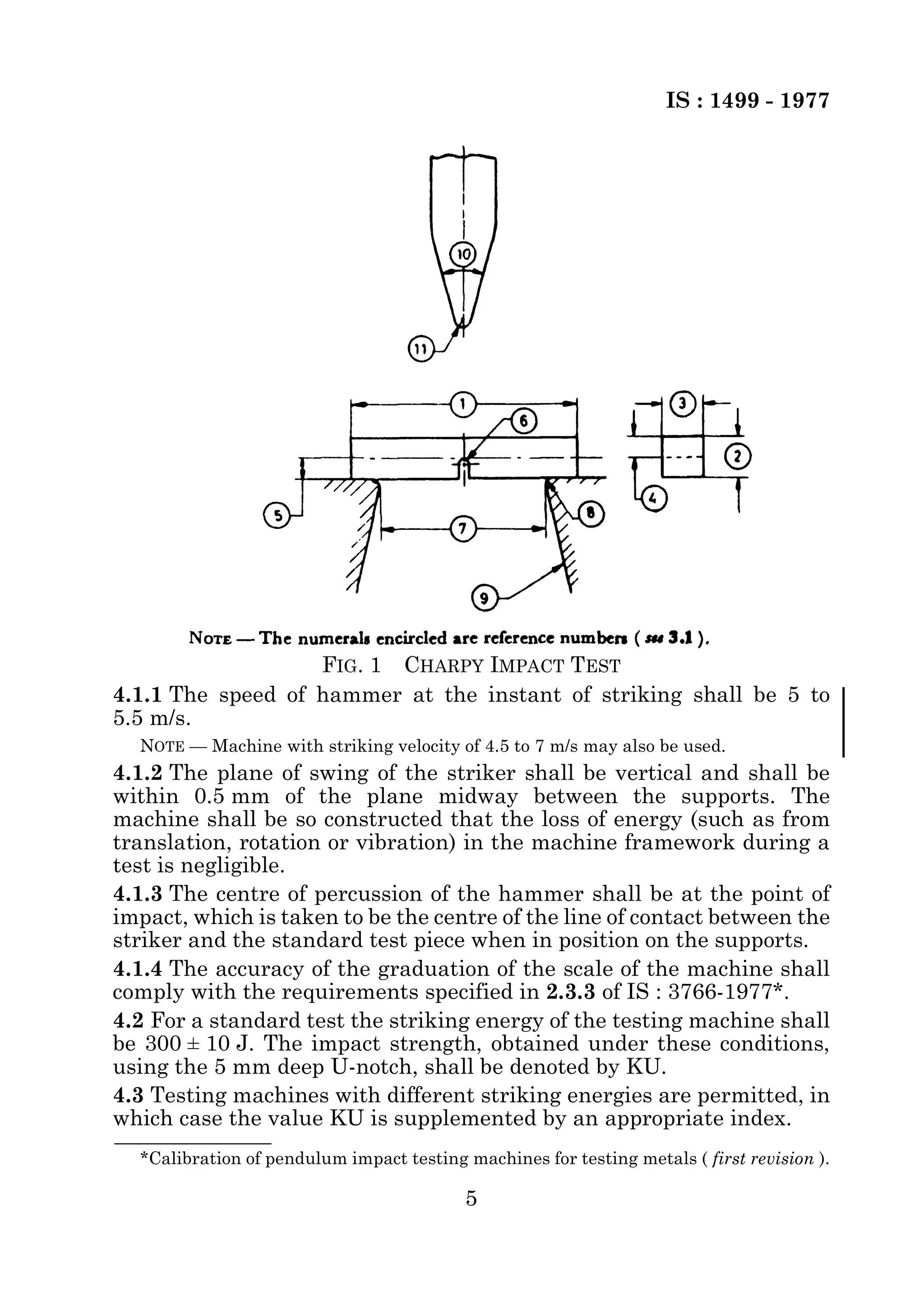
© BIS 2003 
B U R E A U O F I N D I A N S T A N D A R D S 
MANAK BHAVAN, 9 BAHADUR SHAH ZAFAR MARG 
NEW DELHI 110002 
IS : 1499 - 1977 
(Reaffirmed 1999) 
Edition 2.1 
(1980-06) 
Price Group 2 
Indian Standard 
METHOD FOR CHARPY IMPACT TEST 
(U-NOTCH) FOR METALS 
( First Revision ) 
(Incorporating Amendment No. 1) 
UDC 620.178.746.22:669
IS : 1499 - 1977 
Indian Standard 
METHOD FOR CHARPY IMPACT TEST 
(U-NOTCH) FOR METALS 
( First Revision ) 
Methods of Physical Tests Sectional Committee, SMDC 3 
Chairman Representing 
SHRI P. K. CHAKRAVARTY Tata Iron & Steel Co Limited, Jamshedpur 
DR A. S. BHADURI National Test House, Calcutta 
SHRI R. N. BOSE Hindustan Aeronautics Ltd, Bangalore 
SHRI R. N. DATTA Ministry of Defence (DGOF) 
Ministry of Railways 
SHRI D. DUTTA The Indian Tube Co Ltd, Jamshedpur 
SHRI P. K. GANGOPADHYAY Ministry of Defence (DGI) 
SHRI D. K. MUKHERJEE ( Alternate ) 
SHRI N. T. GEORGE Ministry of Defence (R & D) 
SHRI A. K. GUHA Directorate General of Supplies & Disposals 
SHRI M. K. DAS GUPTA National Physical Laboratory (CSIR), New Delhi 
SHRI S. B. IDNANI Blue Star Limited, Bombay 
SHRI S. V. KULKARNI Fuel Instruments & Engineer Pvt Ltd, Ichalkaranji 
SHRI V. M. KULKARNI Usha Martin Black (Wire Ropes) Ltd, Calcutta 
SHRI M. C. KUMARASWAMY Tata Iron & Steel Co Ltd, Jamshedpur 
DR D. M. LAKHIANI The Indian Iron & Steel Co Ltd, Burnpur 
SHRI K. S. LAKSHMINARAYAN Avery India Ltd, Calcutta 
© BIS 2003 
SHRI B. C. BISWAS ( Alternate ) 
DR M. K. MADHEKAR ( Alternate ) 
SHRI D. Y. MOGHE ( Alternate ) 
DEPUTY DIRECTOR (MET)-II, 
RDSO, LUCKNOW 
ASSISTANT DIRECTOR (MET), 
RDSO, LUCKNOW ( Alternate ) 
SHRI G. R. K. MURTY ( Alternate ) 
SHRI P. C. MUSTAFI ( Alternate ) 
SHRI A. L. CHADHA ( Alternate ) 
SHRI J. V. KULKARNI ( Alternate ) 
DR A. CHAKRABORTY ( Alternate ) 
DR T. MUKHERJEE ( Alternate ) 
SHRI R. DUTTA ( Alternate ) 
SHRI R. D. SHARMA ( Alternate ) 
BUREAU OF INDIAN STANDARDS 
Members 
( Continued on page 2 ) 
This publication is protected under the Indian Copyright Act (XIV of 1957) and 
reproduction in whole or in part by any means except with written permission of the 
publisher shall be deemed to be an infringement of copyright under the said Act.
IS : 1499 - 1977 
2 
( Continued from page 1 ) 
Members Representing 
SHRI Y. L. MIDHA Indian Sugar & General Engineering Corporation, 
Yamunanagar 
SHRI MADAN SHARMA ( Alternate ) 
SHRI R. A. PADMANABHAN Central Mechanical Engineering Research Institute 
(CSIR), Durgapur 
SHRI N. A. PRABHU M. N. Dastur & Co (P) Ltd, Calcutta 
SHRI M. PRASAD Hindustan Steel Ltd, Ranchi 
SHRI D. P. GHOSH ( Alternate ) 
SHRI S. RADHAKRISHNAN National Aeronautical Laboratory (CSIR) Bangalore 
DR M. L. BHATIA ( Alternate ) 
SHRI N. V. RAGHAVAN Mining & Allied Machinery Corpn Ltd, Durgapur 
SHRI S. KUMAR ( Alternate ) 
REPRESENTATIVE Union Carbide India Limited, Calcutta 
SHRI F. C. SHARMA Directorate General of Civil Aviation 
SHRI K. C. SRIVASTAVA Bharat Steel Tubes Limited, Ganuar 
SHRI H. K. TANEJA Indian Register of Shipping, Bombay 
SHRI V. N. PANDEY ( Alternate ) 
SHRI A. UMAMAHESWARAN Directorate General of Technical Development 
DR VED PRAKASH National Metallurgical Laboratory (CSIR), 
Jamshedpur 
DR D. J. CHAKRAVARTI ( Alternate ) 
SHRI H. C. VERMA Associated Instrument Manufacturers’ (India) Pvt 
Ltd, New Delhi 
SHRI O. P. CHUGH ( Alternate ) 
SHRI C. R. RAMA RAO, 
Director (Struc & Met) 
Director General, ISI ( Ex-officio Member ) 
Secretary 
SHRI B. MUKHERJI 
Deputy Director (Metals), ISI
IS : 1499 - 1977 
Indian Standard 
METHOD FOR CHARPY IMPACT TEST 
(U-NOTCH) FOR METALS 
( First Revision ) 
0. F O R E W O R D 
0.1 This Indian Standard (First Revision) was adopted by the Indian 
Standards Institution on 15 November 1977, after the draft finalized 
by the Methods of Physical Tests Sectional Committee had been 
approved by the Structural and Metals Division Council. 
0.2 This standard was first published in 1959. Since then considerable 
work has been done by ISO on this subject. Consequently this revision 
has been prepared on the basis of the International Standard 
ISO 83-1976 Steel-Charpy Impact Test (U-Notch). Assistance has also 
been derived from BS 131 : Part 3 : 1972 Methods for notched bar 
tests: Part 3 The charpy U-notch impact test on metals. 
0.3 The following major modifications have been incorporated in this 
revision: 
a) Scope of the standard have been modified to include all metals. 
b) In addition to the standard test piece, two subsidiary test pieces 
having a width of 7.5 mm or 5 mm have been specified. Any of 
these test pieces may be used when the standard test piece 
cannot be obtained from the material. 
c) In accordance with the decision taken at the ISO level, the impact 
energy is expressed in joules and is not related to the 
cross-sectional area of the material under the notch. 
0.4 This edition 2.1 incorporates Amendment No. 1 (June 1980). Side 
bar indicates modification of the text as the result of incorporation of 
the amendment. 
0.5 In reporting the result of a test made in accordance with this 
standard, if the final value, observed or calculated, is to be rounded off, 
it shall be done in accordance with IS : 2-1960*. 
1. SCOPE 
1.1 This standard specifies the conditions for carrying out the charpy 
impact test (U-notch) for determining the impact strength of metals. 
*Rules for rounding off numerical values ( revised ). 
3
IS : 1499 - 1977 
2. PRINCIPLE OF TEST 
2.1 The test consists of measuring the energy absorbed in breaking by 
one blow from a swinging hammer, under prescribed conditions, a test 
piece U-notched in the middle and supported at each end. 
3. REFERENCE NUMBERS 
3.1 The following reference numbers have been used in this standard 
( see Fig. 1 ): 
Reference Number Designation 
1 Length of test piece 
2 Thickness of test piece 
3 Width of test piece 
4 Thickness of test piece minus 
4. TESTING MACHINE 
4.1 The testing machine shall be constructed and installed steady and 
rigid. The dimensions of the machine shall be as follows: 
4 
depth of notch 
5 Depth of notch 
6 Radius of curvature of base of 
notch 
7 Distance between supports 
8 Radius of curvature of supports 
9 Taper of supports 
10 Angle at tip of hammer 
11 Radius of curvature of the tip of 
hammer 
Ref No. Item Dimension 
7 Distance between 
supports 
40.0 
8 Radius of curvature of 
supports 
1.0 
9 Taper of supports 1 ± 0.1 in 5 slope 
10 Angle at tip of hammer 30° ± 1° 
11 Radius of curvature of 
the tip of hammer 
2.0 
+0.5 
–0 mm 
+0.5 
–0 mm 
+0.5 
–0 mm
IS : 1499 - 1977 
FIG. 1 CHARPY IMPACT TEST 
4.1.1 The speed of hammer at the instant of striking shall be 5 to 
5.5 m/s. 
NOTE — Machine with striking velocity of 4.5 to 7 m/s may also be used. 
4.1.2 The plane of swing of the striker shall be vertical and shall be 
within 0.5 mm of the plane midway between the supports. The 
machine shall be so constructed that the loss of energy (such as from 
translation, rotation or vibration) in the machine framework during a 
test is negligible. 
4.1.3 The centre of percussion of the hammer shall be at the point of 
impact, which is taken to be the centre of the line of contact between the 
striker and the standard test piece when in position on the supports. 
4.1.4 The accuracy of the graduation of the scale of the machine shall 
comply with the requirements specified in 2.3.3 of IS : 3766-1977*. 
4.2 For a standard test the striking energy of the testing machine shall 
be 300 ± 10 J. The impact strength, obtained under these conditions, 
using the 5 mm deep U-notch, shall be denoted by KU. 
4.3 Testing machines with different striking energies are permitted, in 
which case the value KU is supplemented by an appropriate index. 
*Calibration of pendulum impact testing machines for testing metals ( first revision ). 
5
IS : 1499 - 1977 
4.4 For a test, in which a standard test piece, with a notch other than 5 
mm deep, is used, the symbol KU shall be supplemented by indices 
denoting both the striking energy of the machine and the depth of the 
notch. 
Examples: 
a) KU 100/3 : striking energy 100 J, 3 mm deep notch. 
b) KU 300/3 : normal striking energy, 3 mm deep notch. 
4.5 The testing machine shall be verified in accordance with 
IS : 3766-1972* and shall comply with the relevant requirements of 
that standard. 
5. TEST PIECE 
5.1 The test piece shall be machined all over and shall be 55.00 mm 
long and in the centre of the length of one face there shall be a U-notch 
of specified depth with 1 mm root radius. The standard test piece and 
the subsidiary test pieces shall have dimensions and tolerances 
specified in Table 1. 
TABLE 1 DIMENSIONS AND TOLERANCES OF FERROUS AND 
NON-FERROUS TEST PIECES 
( Clauses 5.1 and 6.1 ) 
 
*Calibration of pendulum impact testing machines for testing metals ( first revision ). 
6 
SL 
NO. 
ITEM NOMINAL 
DIMENSION 
MACHINING TOLERANCES 
Ferrous Test 
Pieces 
Non-ferrous 
Test Pieces 
(1) (2) (3) (4) (5) 
mm mm mm 
i) Length 55 ± 0.60 ± 0.5 
ii) Width: 
Standard test piece 10 ± 0.11 ± 0.05 
Subsidiary test pieces 7.5 ± 0.11 ± 0.05 
5 ± 0.05 ± 0.025 
iii) Thickness 10 ± 0.11 ± 0.05 
iv) Root radius of notch 1.0 ± 0.07 ± 0.07 
v) Depth below notch 8 (2 mm notch) 
7 (3 mm notch) 
5 (5 mm notch) 
± 0.09 
± 0.09 
± 0.09 
± 0.05 
± 0.05 
± 0.05 
vi) Distance of centre of notch from 
ends of test piece 
27.5 ± 0.42 ± 0.25 
vii) Angle between plane of 
symmetry of notch and 
longitudinal axis of test piece 
90° ± 2° ± 2°
IS : 1499 - 1977 
5.1.1 The standard test piece shall be of square cross-section 
10 mm × 10 mm. Where the standard test piece cannot be obtained 
from the material, one of the subsidiary test pieces, having a 
rectangular cross-section shall be used with the notch cut in one of the 
narrower faces. 
NOTE — It is emphasized that only results on test pieces of identical dimensions 
should be compared as no satisfactory correlation between results obtained from 
different sizes of test pieces has been established. 
5.2 The notch may be made by any machining method. The notch shall 
be carefully prepared so that no grooves appear at the base of the 
notch. 
6. TEST PROCEDURE 
6.1 Position of Test Piece — The test piece shall lie squarely against 
the supports with the plane of symmetry of the notch within 0.5 mm of 
the plane of swing of the striker. In order to achieve this, where an end 
stop is used to position the test piece in the machine, it may be 
necessary to machine the test piece length to tolerances closer than 
those given in Table 1. 
6.2 Temperature of Test — The temperature of the test piece at the 
moment of breaking shall not differ from the specified temperature by 
more than ± 2°C, unless some other tolerance is agreed. If the 
temperature of testing is not specified, it shall be taken as 27°C subject 
to the above tolerance. In all cases, including when the test is required 
to be carried out at ambient temperature, the test temperature shall 
be recorded. 
6.2.1 When the impact properties are determined at specified sub-zero 
temperatures or at specified temperature up to 200°C, the test piece 
shall be brought to an appropriate temperature by immersion in a 
bath. In all cases the period of immersion of the test piece and the 
appliances in the bath at the required temperature shall be not less 
than 10 minutes and the test piece shall be broken within 6 seconds 
from the time of removal from bath. 
NOTE — For tests at temperatures within the range 20 to 100°C, an oil bath is to be 
preferred to a water bath. 
6.2.2 For test at temperatures above 200°C, the test piece shall be 
heated in an oven or salt bath, sufficient time at the required 
temperature being allowed for the test piece to reach this temperature. 
The test piece shall be broken within 6 seconds from the time of 
removal from bath or oven. 
6.3 Number of Tests — Unless otherwise stated in the relevant 
material specification, an impact test shall consist of three specimens 
taken from a single test coupon or test location, the average value of 
which shall comply with the specified minimum with not more than 
7
IS : 1499 - 1977 
one value being below the specified minimum, but in no case less than 
either two-thirds of the specified minimum value or 7 Joules, 
whichever is greater. If more than one value is below the specified 
minimum, or if any one value is less than the greater of 7 Joules or 
two-thirds of the specified minimum, a retest of three additional 
specimens shall be made, each of which should have a value equal to or 
exceeding the specified minimum. 
6.4 Unbroken Test Piece — If during the test, the test piece is not 
completely broken, the impact value obtained is indefinite. The test 
report should state that the test piece was not broken by striking 
energy of the testing machine. 
8
Bureau of Indian Standards 
BIS is a statutory institution established under the Bureau of Indian Standards Act, 1986 to promote 
harmonious development of the activities of standardization, marking and quality certification of 
goods and attending to connected matters in the country. 
Copyright 
BIS has the copyright of all its publications. No part of these publications may be reproduced in any 
form without the prior permission in writing of BIS. This does not preclude the free use, in the course 
of implementing the standard, of necessary details, such as symbols and sizes, type or grade 
designations. Enquiries relating to copyright be addressed to the Director (Publications), BIS. 
Review of Indian Standards 
Amendments are issued to standards as the need arises on the basis of comments. Standards are also 
reviewed periodically; a standard along with amendments is reaffirmed when such review indicates 
that no changes are needed; if the review indicates that changes are needed, it is taken up for 
revision. Users of Indian Standards should ascertain that they are in possession of the latest 
amendments or edition by referring to the latest issue of ‘BIS Catalogue’ and ‘Standards : Monthly 
Additions’. 
This Indian Standard has been developed by Technical Committee : SMDC 3 
Amendments Issued Since Publication 
Amend No. Date of Issue 
Amd. No. 1 June 1980 
BUREAU OF INDIAN STANDARDS 
Headquarters: 
Manak Bhavan, 9 Bahadur Shah Zafar Marg, New Delhi 110002. 
Telephones: 323 01 31, 323 33 75, 323 94 02 
Telegrams: Manaksanstha 
(Common to all offices) 
Regional Offices: Telephone 
Central : Manak Bhavan, 9 Bahadur Shah Zafar Marg 
NEW DELHI 110002 
323 76 17 
323 38 41 
Eastern : 1/14 C. I. T. Scheme VII M, V. I. P. Road, Kankurgachi 
KOLKATA 700054 
   
337 84 99, 337 85 61 
337 86 26, 337 91 20 
   
Northern : SCO 335-336, Sector 34-A, CHANDIGARH 160022 60 38 43 
60 20 25 
   
Southern : C. I. T. Campus, IV Cross Road, CHENNAI 600113 235 02 16, 235 04 42 
235 15 19, 235 23 15 
Western : Manakalaya, E9 MIDC, Marol, Andheri (East) 
MUMBAI 400093 
832 92 95, 832 78 58 
832 78 91, 832 78 92 
   
   
Branches : AHMEDABAD. BANGALORE. BHOPAL. BHUBANESHWAR. COIMBATORE. 
FARIDABAD. GHAZIABAD. GUWAHATI. HYDERABAD. JAIPUR. KANPUR. LUCKNOW. 
NAGPUR. NALAGARH. PATNA. PUNE. RAJKOT. THIRUVANANTHAPURAM. 
VISHAKHAPATNAM

1499 charpy impact tes

  • 1.
    © BIS 2003 B U R E A U O F I N D I A N S T A N D A R D S MANAK BHAVAN, 9 BAHADUR SHAH ZAFAR MARG NEW DELHI 110002 IS : 1499 - 1977 (Reaffirmed 1999) Edition 2.1 (1980-06) Price Group 2 Indian Standard METHOD FOR CHARPY IMPACT TEST (U-NOTCH) FOR METALS ( First Revision ) (Incorporating Amendment No. 1) UDC 620.178.746.22:669
  • 2.
    IS : 1499- 1977 Indian Standard METHOD FOR CHARPY IMPACT TEST (U-NOTCH) FOR METALS ( First Revision ) Methods of Physical Tests Sectional Committee, SMDC 3 Chairman Representing SHRI P. K. CHAKRAVARTY Tata Iron & Steel Co Limited, Jamshedpur DR A. S. BHADURI National Test House, Calcutta SHRI R. N. BOSE Hindustan Aeronautics Ltd, Bangalore SHRI R. N. DATTA Ministry of Defence (DGOF) Ministry of Railways SHRI D. DUTTA The Indian Tube Co Ltd, Jamshedpur SHRI P. K. GANGOPADHYAY Ministry of Defence (DGI) SHRI D. K. MUKHERJEE ( Alternate ) SHRI N. T. GEORGE Ministry of Defence (R & D) SHRI A. K. GUHA Directorate General of Supplies & Disposals SHRI M. K. DAS GUPTA National Physical Laboratory (CSIR), New Delhi SHRI S. B. IDNANI Blue Star Limited, Bombay SHRI S. V. KULKARNI Fuel Instruments & Engineer Pvt Ltd, Ichalkaranji SHRI V. M. KULKARNI Usha Martin Black (Wire Ropes) Ltd, Calcutta SHRI M. C. KUMARASWAMY Tata Iron & Steel Co Ltd, Jamshedpur DR D. M. LAKHIANI The Indian Iron & Steel Co Ltd, Burnpur SHRI K. S. LAKSHMINARAYAN Avery India Ltd, Calcutta © BIS 2003 SHRI B. C. BISWAS ( Alternate ) DR M. K. MADHEKAR ( Alternate ) SHRI D. Y. MOGHE ( Alternate ) DEPUTY DIRECTOR (MET)-II, RDSO, LUCKNOW ASSISTANT DIRECTOR (MET), RDSO, LUCKNOW ( Alternate ) SHRI G. R. K. MURTY ( Alternate ) SHRI P. C. MUSTAFI ( Alternate ) SHRI A. L. CHADHA ( Alternate ) SHRI J. V. KULKARNI ( Alternate ) DR A. CHAKRABORTY ( Alternate ) DR T. MUKHERJEE ( Alternate ) SHRI R. DUTTA ( Alternate ) SHRI R. D. SHARMA ( Alternate ) BUREAU OF INDIAN STANDARDS Members ( Continued on page 2 ) This publication is protected under the Indian Copyright Act (XIV of 1957) and reproduction in whole or in part by any means except with written permission of the publisher shall be deemed to be an infringement of copyright under the said Act.
  • 3.
    IS : 1499- 1977 2 ( Continued from page 1 ) Members Representing SHRI Y. L. MIDHA Indian Sugar & General Engineering Corporation, Yamunanagar SHRI MADAN SHARMA ( Alternate ) SHRI R. A. PADMANABHAN Central Mechanical Engineering Research Institute (CSIR), Durgapur SHRI N. A. PRABHU M. N. Dastur & Co (P) Ltd, Calcutta SHRI M. PRASAD Hindustan Steel Ltd, Ranchi SHRI D. P. GHOSH ( Alternate ) SHRI S. RADHAKRISHNAN National Aeronautical Laboratory (CSIR) Bangalore DR M. L. BHATIA ( Alternate ) SHRI N. V. RAGHAVAN Mining & Allied Machinery Corpn Ltd, Durgapur SHRI S. KUMAR ( Alternate ) REPRESENTATIVE Union Carbide India Limited, Calcutta SHRI F. C. SHARMA Directorate General of Civil Aviation SHRI K. C. SRIVASTAVA Bharat Steel Tubes Limited, Ganuar SHRI H. K. TANEJA Indian Register of Shipping, Bombay SHRI V. N. PANDEY ( Alternate ) SHRI A. UMAMAHESWARAN Directorate General of Technical Development DR VED PRAKASH National Metallurgical Laboratory (CSIR), Jamshedpur DR D. J. CHAKRAVARTI ( Alternate ) SHRI H. C. VERMA Associated Instrument Manufacturers’ (India) Pvt Ltd, New Delhi SHRI O. P. CHUGH ( Alternate ) SHRI C. R. RAMA RAO, Director (Struc & Met) Director General, ISI ( Ex-officio Member ) Secretary SHRI B. MUKHERJI Deputy Director (Metals), ISI
  • 4.
    IS : 1499- 1977 Indian Standard METHOD FOR CHARPY IMPACT TEST (U-NOTCH) FOR METALS ( First Revision ) 0. F O R E W O R D 0.1 This Indian Standard (First Revision) was adopted by the Indian Standards Institution on 15 November 1977, after the draft finalized by the Methods of Physical Tests Sectional Committee had been approved by the Structural and Metals Division Council. 0.2 This standard was first published in 1959. Since then considerable work has been done by ISO on this subject. Consequently this revision has been prepared on the basis of the International Standard ISO 83-1976 Steel-Charpy Impact Test (U-Notch). Assistance has also been derived from BS 131 : Part 3 : 1972 Methods for notched bar tests: Part 3 The charpy U-notch impact test on metals. 0.3 The following major modifications have been incorporated in this revision: a) Scope of the standard have been modified to include all metals. b) In addition to the standard test piece, two subsidiary test pieces having a width of 7.5 mm or 5 mm have been specified. Any of these test pieces may be used when the standard test piece cannot be obtained from the material. c) In accordance with the decision taken at the ISO level, the impact energy is expressed in joules and is not related to the cross-sectional area of the material under the notch. 0.4 This edition 2.1 incorporates Amendment No. 1 (June 1980). Side bar indicates modification of the text as the result of incorporation of the amendment. 0.5 In reporting the result of a test made in accordance with this standard, if the final value, observed or calculated, is to be rounded off, it shall be done in accordance with IS : 2-1960*. 1. SCOPE 1.1 This standard specifies the conditions for carrying out the charpy impact test (U-notch) for determining the impact strength of metals. *Rules for rounding off numerical values ( revised ). 3
  • 5.
    IS : 1499- 1977 2. PRINCIPLE OF TEST 2.1 The test consists of measuring the energy absorbed in breaking by one blow from a swinging hammer, under prescribed conditions, a test piece U-notched in the middle and supported at each end. 3. REFERENCE NUMBERS 3.1 The following reference numbers have been used in this standard ( see Fig. 1 ): Reference Number Designation 1 Length of test piece 2 Thickness of test piece 3 Width of test piece 4 Thickness of test piece minus 4. TESTING MACHINE 4.1 The testing machine shall be constructed and installed steady and rigid. The dimensions of the machine shall be as follows: 4 depth of notch 5 Depth of notch 6 Radius of curvature of base of notch 7 Distance between supports 8 Radius of curvature of supports 9 Taper of supports 10 Angle at tip of hammer 11 Radius of curvature of the tip of hammer Ref No. Item Dimension 7 Distance between supports 40.0 8 Radius of curvature of supports 1.0 9 Taper of supports 1 ± 0.1 in 5 slope 10 Angle at tip of hammer 30° ± 1° 11 Radius of curvature of the tip of hammer 2.0 +0.5 –0 mm +0.5 –0 mm +0.5 –0 mm
  • 6.
    IS : 1499- 1977 FIG. 1 CHARPY IMPACT TEST 4.1.1 The speed of hammer at the instant of striking shall be 5 to 5.5 m/s. NOTE — Machine with striking velocity of 4.5 to 7 m/s may also be used. 4.1.2 The plane of swing of the striker shall be vertical and shall be within 0.5 mm of the plane midway between the supports. The machine shall be so constructed that the loss of energy (such as from translation, rotation or vibration) in the machine framework during a test is negligible. 4.1.3 The centre of percussion of the hammer shall be at the point of impact, which is taken to be the centre of the line of contact between the striker and the standard test piece when in position on the supports. 4.1.4 The accuracy of the graduation of the scale of the machine shall comply with the requirements specified in 2.3.3 of IS : 3766-1977*. 4.2 For a standard test the striking energy of the testing machine shall be 300 ± 10 J. The impact strength, obtained under these conditions, using the 5 mm deep U-notch, shall be denoted by KU. 4.3 Testing machines with different striking energies are permitted, in which case the value KU is supplemented by an appropriate index. *Calibration of pendulum impact testing machines for testing metals ( first revision ). 5
  • 7.
    IS : 1499- 1977 4.4 For a test, in which a standard test piece, with a notch other than 5 mm deep, is used, the symbol KU shall be supplemented by indices denoting both the striking energy of the machine and the depth of the notch. Examples: a) KU 100/3 : striking energy 100 J, 3 mm deep notch. b) KU 300/3 : normal striking energy, 3 mm deep notch. 4.5 The testing machine shall be verified in accordance with IS : 3766-1972* and shall comply with the relevant requirements of that standard. 5. TEST PIECE 5.1 The test piece shall be machined all over and shall be 55.00 mm long and in the centre of the length of one face there shall be a U-notch of specified depth with 1 mm root radius. The standard test piece and the subsidiary test pieces shall have dimensions and tolerances specified in Table 1. TABLE 1 DIMENSIONS AND TOLERANCES OF FERROUS AND NON-FERROUS TEST PIECES ( Clauses 5.1 and 6.1 )  *Calibration of pendulum impact testing machines for testing metals ( first revision ). 6 SL NO. ITEM NOMINAL DIMENSION MACHINING TOLERANCES Ferrous Test Pieces Non-ferrous Test Pieces (1) (2) (3) (4) (5) mm mm mm i) Length 55 ± 0.60 ± 0.5 ii) Width: Standard test piece 10 ± 0.11 ± 0.05 Subsidiary test pieces 7.5 ± 0.11 ± 0.05 5 ± 0.05 ± 0.025 iii) Thickness 10 ± 0.11 ± 0.05 iv) Root radius of notch 1.0 ± 0.07 ± 0.07 v) Depth below notch 8 (2 mm notch) 7 (3 mm notch) 5 (5 mm notch) ± 0.09 ± 0.09 ± 0.09 ± 0.05 ± 0.05 ± 0.05 vi) Distance of centre of notch from ends of test piece 27.5 ± 0.42 ± 0.25 vii) Angle between plane of symmetry of notch and longitudinal axis of test piece 90° ± 2° ± 2°
  • 8.
    IS : 1499- 1977 5.1.1 The standard test piece shall be of square cross-section 10 mm × 10 mm. Where the standard test piece cannot be obtained from the material, one of the subsidiary test pieces, having a rectangular cross-section shall be used with the notch cut in one of the narrower faces. NOTE — It is emphasized that only results on test pieces of identical dimensions should be compared as no satisfactory correlation between results obtained from different sizes of test pieces has been established. 5.2 The notch may be made by any machining method. The notch shall be carefully prepared so that no grooves appear at the base of the notch. 6. TEST PROCEDURE 6.1 Position of Test Piece — The test piece shall lie squarely against the supports with the plane of symmetry of the notch within 0.5 mm of the plane of swing of the striker. In order to achieve this, where an end stop is used to position the test piece in the machine, it may be necessary to machine the test piece length to tolerances closer than those given in Table 1. 6.2 Temperature of Test — The temperature of the test piece at the moment of breaking shall not differ from the specified temperature by more than ± 2°C, unless some other tolerance is agreed. If the temperature of testing is not specified, it shall be taken as 27°C subject to the above tolerance. In all cases, including when the test is required to be carried out at ambient temperature, the test temperature shall be recorded. 6.2.1 When the impact properties are determined at specified sub-zero temperatures or at specified temperature up to 200°C, the test piece shall be brought to an appropriate temperature by immersion in a bath. In all cases the period of immersion of the test piece and the appliances in the bath at the required temperature shall be not less than 10 minutes and the test piece shall be broken within 6 seconds from the time of removal from bath. NOTE — For tests at temperatures within the range 20 to 100°C, an oil bath is to be preferred to a water bath. 6.2.2 For test at temperatures above 200°C, the test piece shall be heated in an oven or salt bath, sufficient time at the required temperature being allowed for the test piece to reach this temperature. The test piece shall be broken within 6 seconds from the time of removal from bath or oven. 6.3 Number of Tests — Unless otherwise stated in the relevant material specification, an impact test shall consist of three specimens taken from a single test coupon or test location, the average value of which shall comply with the specified minimum with not more than 7
  • 9.
    IS : 1499- 1977 one value being below the specified minimum, but in no case less than either two-thirds of the specified minimum value or 7 Joules, whichever is greater. If more than one value is below the specified minimum, or if any one value is less than the greater of 7 Joules or two-thirds of the specified minimum, a retest of three additional specimens shall be made, each of which should have a value equal to or exceeding the specified minimum. 6.4 Unbroken Test Piece — If during the test, the test piece is not completely broken, the impact value obtained is indefinite. The test report should state that the test piece was not broken by striking energy of the testing machine. 8
  • 10.
    Bureau of IndianStandards BIS is a statutory institution established under the Bureau of Indian Standards Act, 1986 to promote harmonious development of the activities of standardization, marking and quality certification of goods and attending to connected matters in the country. Copyright BIS has the copyright of all its publications. No part of these publications may be reproduced in any form without the prior permission in writing of BIS. This does not preclude the free use, in the course of implementing the standard, of necessary details, such as symbols and sizes, type or grade designations. Enquiries relating to copyright be addressed to the Director (Publications), BIS. Review of Indian Standards Amendments are issued to standards as the need arises on the basis of comments. Standards are also reviewed periodically; a standard along with amendments is reaffirmed when such review indicates that no changes are needed; if the review indicates that changes are needed, it is taken up for revision. Users of Indian Standards should ascertain that they are in possession of the latest amendments or edition by referring to the latest issue of ‘BIS Catalogue’ and ‘Standards : Monthly Additions’. This Indian Standard has been developed by Technical Committee : SMDC 3 Amendments Issued Since Publication Amend No. Date of Issue Amd. No. 1 June 1980 BUREAU OF INDIAN STANDARDS Headquarters: Manak Bhavan, 9 Bahadur Shah Zafar Marg, New Delhi 110002. Telephones: 323 01 31, 323 33 75, 323 94 02 Telegrams: Manaksanstha (Common to all offices) Regional Offices: Telephone Central : Manak Bhavan, 9 Bahadur Shah Zafar Marg NEW DELHI 110002 323 76 17 323 38 41 Eastern : 1/14 C. I. T. Scheme VII M, V. I. P. Road, Kankurgachi KOLKATA 700054    337 84 99, 337 85 61 337 86 26, 337 91 20    Northern : SCO 335-336, Sector 34-A, CHANDIGARH 160022 60 38 43 60 20 25    Southern : C. I. T. Campus, IV Cross Road, CHENNAI 600113 235 02 16, 235 04 42 235 15 19, 235 23 15 Western : Manakalaya, E9 MIDC, Marol, Andheri (East) MUMBAI 400093 832 92 95, 832 78 58 832 78 91, 832 78 92       Branches : AHMEDABAD. BANGALORE. BHOPAL. BHUBANESHWAR. COIMBATORE. FARIDABAD. GHAZIABAD. GUWAHATI. HYDERABAD. JAIPUR. KANPUR. LUCKNOW. NAGPUR. NALAGARH. PATNA. PUNE. RAJKOT. THIRUVANANTHAPURAM. VISHAKHAPATNAM