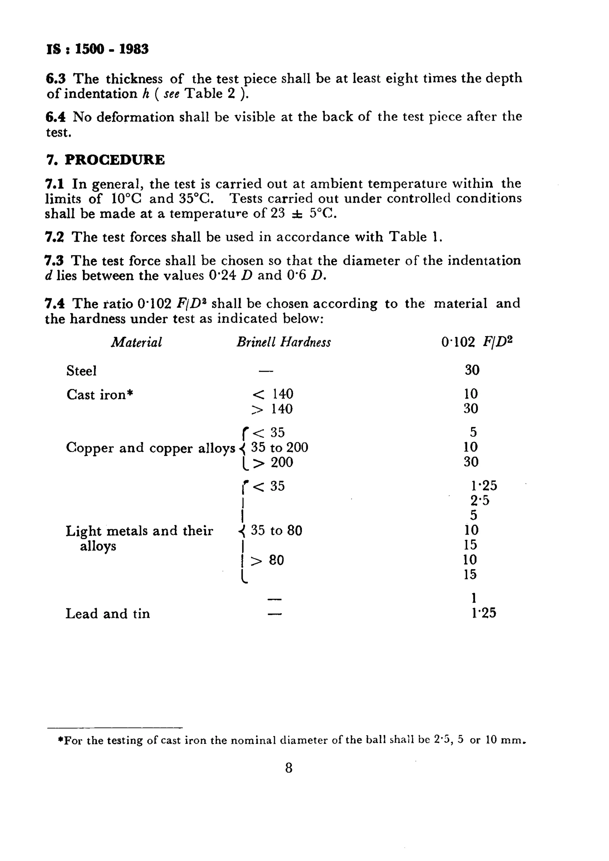
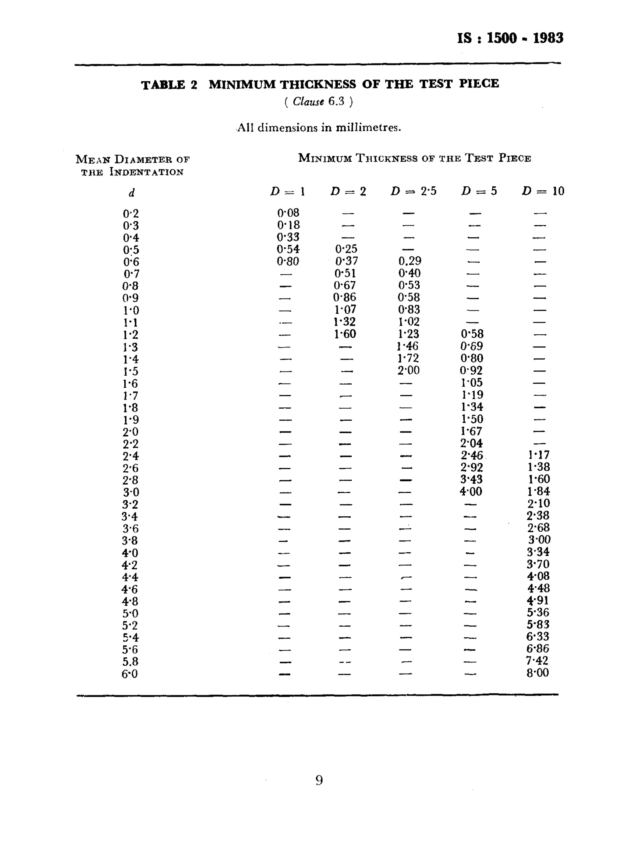
IS : 1500 - 1983 
(Reaffirmed 1996) 
Indian Standard 
METI-iOD FOR 
BRINELL HARDNESS TEST FOR 
METALLIC MATERIALS 
( Second Revision ) 
ThirRde print AUGUST 1997 
UDC 669 : 620.178.152.22 
0 Copyright 1983 
BUREAU OF INDIAN STANDARDS 
MANAK BHAVAN, 9 BAHADUR SHAH ZAFAR MARG 
NEW DELHI 110002 
Gr 3 November 1983~
IS : 1500 - 1983 
Indian Standard 
METHOD FOR 
BRINELL HARDNESS TEST FOR 
METALLIC MATERIALS 
( Second Revision ) 
Methods of Physical Tests Sectional Committee, SMIX 3 
Chairmar~ R+resentin,~ 
SHRI P. K. CIIAKItAVAaTY The Tata Iron & Steel Co Ltd,,Jamshedpur 
Members 
SHRI R. K. ABROL Bharat Steel Tuhcs Ltd, Ganaur 
SHRI KA??WAI,JIT SINCH ARORA ( Alternate ) 
S~IRI SUJIT KUMAR BASU M. N. Dastur & Co (I’) Ltd, Calcutta 
SHRI S. SEN GWPTA ( Alfernnte ) 
DR A. CHAKKABORTY Usha Martin Black ( Wire Ropes ) Ltd, Calcutta 
SHRI H. MAHESWARY ( Alternate ) 
SHRI K. K. CHEKIAN Indian Aluminium Co Ltd, Calcutta 
SHRI PANKAJ DE ( Altern& ) 
SHRI 0. P. CIWGR Associated Instrument Manufacturers’ ( India ) 
Private Ltd, New Delhi 
SHRI V. N. NANDA ( Alternate ) 
Da R. P. DAMBAI. Indian Telephone Industries Ltd, Bangalore 
SHIU N. NAG EAJ ( Allmale ) 
SHRI M. K. DAS 6 UPTA National Physical Laboratory ( CSIR ), New Delhi 
DEPUTY DIRECTOR ( MET-:! ), Ministry of Railways 
RDSO, Luch-NOW 
ASSISTANT RES. OFFICER 
( MET-~ ), RDSO, LUCKNOW ( Altrrnate ) 
SHRI D. DUTTA The Indian Tube Co Ltd, Jamshedpur 
SRRI C. B. LUNAWAT ( Alternate ) 
SHRI J. G. EI~RY Steel .Luthority of India Ltd ( Bokaro Steel Plant ) 
SHRI K. G. GARC Directorate General of Technical Development 
and Production ( Air ), New Delhi 
SRRI P. RAGIIOTIIAMA RAO ( Akmatc ) 
SHRI A. GHOSH National Test House, Calcutta 
SHRI D. S. MAJU~ZDAR ( Alternate ) 
S~nr S. A. HAQUE Tata Iron and Steel Co Ltd, Jamshedpur 
SHRI A. S. WALIA ( Alternate) 
SHEI S. B. Inas~r Blue Star Limited. Bornhay 
SI~RI G. S. SUTI ( Altrrnntc ) 
Smr s. v. KUI.ICAI:NI Fuel Instrumrnts & Engineers Pvt Ltd, Ichalkaranji 
Srra~J. V. K~L~<ARNI ( Allernafe ) 
( Conlinzceodn p ap 2 ) 
reproduction in whole or in part by any means except with written permimion of tbe 
oublishrr shall be deemed to be an infringement of copyright under the said Act, 
~. --.
Is:uoo-1983 
( Continued from page 1 ) 
Members 
SARIS. KUMAR 
Representing 
Mining & Allied Machinery Corporation Ltd, 
Durgapur 
SHRI K. S. L.U~SHMINARAYAN Avery India Ltd, Calcutta 
SHRI R. D. SHARMA ( Alternale ) 
SHRI S. R. MAZTJMDAH. Ministry of Defence ( DGI ) 
SHRI A. K. CHAKROBOKTY ( Alternote ) 
SHRI R. A. PADMANABHAN Central Mechanical Engineering Research Institute 
( CSIK ), Durgapur 
SHRI M. PRASAD SteeI Authority of India Ltd, Ranchi 
SHRI N. GOP~LAKRISHNA( Alternate ) 
SHRI S. RADHAKRISHNAN National. Aeronautical Laboratory ( CSIR )> 
Bangalore 
DR V. SRINIVASAN ( Alternate ) 
SHRI R. N. S~HA Directorate General of Supplies and Disposals, 
New Delhi 
SHRI S. K. PANDEY ( Alternate ) 
SHRI D. N. SARKAR Ministry of Defence ( DGOF ) 
SHRI A. R. BASU ( Alternate ) 
SARI F. C. SHAHMA Directorate General of Civil Aviation, New Delhi 
SHRI K. SWAMIAPPAN Ministry of Defencc ( R & D ) 
SHRI II. K. TANEJA Indian Register of Shipping, Bombay 
SHRI V. N. PANDEY ( Alternate ) 
DR V. RAO National Metallurgical Laboratory ( CSIR ), 
Jamshedpur 
Dn D. J. CHAKRAVARTI ( Alternate ) 
SHRI K. RAGHAVENDRAN, Director General, IS1 ( Ex-o&io Member ) 
Director ( Strut & Met ) 
Secretary 
SHRI S. K. GUPT~ 
Deputy Director ( Metals ), IS1 
2
IS:1500 - 1983 
Indian Standard 
METHOD FOR 
BRINELL HARDNESS TEST FOR 
METALLIC MATERIALS 
( Second Revision ) 
0. FOREWORD 
0.1 This Indiau Standard ( Second Revision ) was adopted by the Indian 
Standards Institution on 27 June 1983, after the draft finalized by the 
Methods of Physical Tests Sectional Committee had been approved by 
the Structural and Metals Division Council. 
0.2 This standard was first published in 1959, and then revised 
in 1968. Subsequently, it was decided to revise the standard once more 
so as to have a single reference Indian Standard on method for Brine11 
hardness test for metallic materials, amalgamating three other Indian 
Standards on the subject. 
0.2.1 This standard thus supersedes the following Indian Standards: 
IS : 1789-1961 Method for Brine11 hardness test for grey cast iron 
IS : 1790-1961 Method for Brine11 hardness test for light metals 
and their alloys 
IS : 3054-1965 Method for Brine11 hardness test for copper and 
copper alloys 
0.3 Tables 1 to 5 for Brine11 hardness values for different ball diameters 
and test loads as were given in the previous version of this standard 
( IS : 1500-1968 ) have now been deleted from this standard as the same 
values have been covered in IS : 10588-1983*. However, the load to be 
applied to different types of metals have been incorporated in this revised 
standard, along with the adoption of SI Units. 
0.4 This standar,d is based on IS0 6506-1981 ‘Metallic materials- 
Hardness test - Brine11 test’, prepared by International Organization 
fbr Standardization. 
*Table: of Brine11 hardness vAlues for use in tests made of flat surfaces. 
3
IS:1500-1983 
0.5 In reporting the result of a test or analysis made in accordance with 
this standard, if the final value, observed or calculated, is to be rounded 
off, it shall be done in accordance with IS : 2-1960*. 
1. SCOPE 
1.1 This standard specifies the method for the Brine11 hardness test for 
metallic materials. 
2. PRINCIPLE OF TEST 
2.1 The Brine11 hardness is proportional to the quotient obtaired by 
dividing the test force by the curved surface area of the indentation 
which is assumed IO be spherical and of diameter equal to that of the 
ball. 
2.2 In actual practice an indenter ( hardened steel ball or hard metal ball 
with diameter D ) is forced into the surface of a test piece and the 
diameter of the indentation d left in the surface after removal of the test 
force F is measured. 
3. GENERAL 
3.1 The steel ball indenter is used for materials with a Brine11 hardness 
not exceeding 450. 
3.2 The hard metal ball indenter is used for materials with a Brine11 
hardness not exceeding 650. 
NOTE - The values obtained using a steel ball or a hard metal ball are significantly 
different for hardnesses above 350. 
4. SYMBOLS AND DESIGNATtONS 
4.1 The following symbols have been used in this standard: 
Symbols ( see Fig. 1 and 2 ) Designation 
D Diameter, in millimetres, of the ball 
F Test force, in newtons 
d Mean diameter, in millimetres, of 
the indentation 
h Depth in millimetres, of the indenta-tion 
=D--D2-d’ 
2 
‘Rules for rounding off numerical values ( revised ). 
4
HBS 
I&V 
IS : 1588 - 1983 
Brine11 hardness 
= Constant X 
Test force 
Surface area of indentation 
= 0,102 x - 2F 
_-- 
x D(D - d D"- - da) 
1 
NOTE - COWAnt = + = p 9806 65 
= 0.102 
F 7 
i 
0 
__+-- 
/ , 
’ ,;,. 
FIG. 1 PRINCIPLE OF TEST 
I cl 
_- -- 
@ 
FIG. 2 MEASUREMENT OF 
INDENTATION 
5
IS : 1500 - 1983 
4.2 The Brine11 hardness is denoted by the following symbols; 
a) HBS in cases where a steel ball is used; and 
b) HBW in cases where a hardmetal ball is used. 
NOTE - In previous standards, in case when a steel ball was used, the Brine11 
hardness was denoted by HB. 
4.3 The symbol HBS or HHW is preceded by the hardness value and 
supplemented by an index indicating the te>t conditions, in the following 
order: 
a) Diameter of the ball, in millimetres; 
b) A figure representing the test force ( see Table 1 ); and 
c) Duration of loading, 
time ( see 7.6 ). 
in seconds, if different from the specified 
Examples: 
350 HBS 5/750 = Brine11 hardness of 350 determined with a steel 
ball of 5 mm diameter and with a test force of 7.355 kN applied for 
10 to 15 seconds. 
600 HBW l/30/20 = Brine11 hardness of 600 determined with a 
hard metal ball of 1 mm diameter and with a test force of 294.2 N 
applied for 20 seconds. 
5. APPARATUS 
5.1 Testing machine, capable of applying the predetermined test force or 
forces within the range of 9.807 N to 29.42 KN, in accordance with 
IS : 2281-1968*. 
5.2 Indenter - Indenter is a hardened and polished steel ball or hard 
metal ball, as specified in IS : 2281-1968*. 
5.3 Measuring Device - Measuring device as specified in IS : 2281- 
1968*. 
6. TEST PIECE 
6.1 The test shall be carried out on a surface which is smooth and even, 
free from oxide scale, foreign matter and, in particular, coniljletely free 
from lubricants. 
6.2 Preparation shall be carried out in such a way that any alteration of 
the surface for example due to heat or cold working, is minimized. 
*Method for verilication of Brine11 hardness testing machints ( jrsl rcrision ), 
6
IS : 1500 - 1983 
TABLE 1 TEST FORCES FOR DETERMINATION OF BRINELL 
HARDNESS VALUES 
( Clauses 4.3 and 7.2 ) 
HARDNESS SYMBOL BALL 
L)IAMETER 
D 
HBS ( HBW ) 10/3 000 
HBS ( HBW ) 10/l 500 
HBS ( HBW ) 10/l 000 
HBS ( HBW ) lo/500 
HBS ( HBW ) IO/250 
HBS ( HBW ) lo/l25 
HBS ( HBW ) lO/lOO 
HBS ( HBW ) 5/750 
HBS ( HBW ) 5/250 
HBS ( HBW ) 5/125 
HBS ( HBW ) 5/62.5 
HBS ( HBW ) 5/31’25 
HBS ( HBW ) 5/25 
HBS ( HBW ) 2’5/187’5 
HBS ( HBW ) 2.5/62*5 
HBS ( HBW ) 2*5/31*25 
HBS ( HBW ) 2’5/15*625 
HBS ( HBW ) 2.5/7.812 5 
HBS ( HBW ) 2.5/6.25 
HBS ( HBW ) 2/120 
HBS ( HBW ) 2/k 
HBS ( HBW ) 2/20 
HBS ( HBW ) 2/10 
HBS ( HBW ) 2/5 
HBS ( HBW ) 2/4 
HBS ( HBW ) l/30 
HBS (HBW ) l/IO 
HBS (HBW) l/5 
HBS ( HBW ) l/2*5 
HBS ( HBW ) l/l’25 
HBS(HBW) l/l 
O-102 F 
G 
TEST FORCE 
F 
NOMINAL 
VALUE 
10 30 29.42 kN 
10 15 1471 kN 
10 10 9.807 kN 
10 5 4.903 kN 
10 2.5 2’452 kN 
10 l-25 1.226 kN 
10 1 980.7 N 
5 30 7-355 kN 
5 10 2’452 kN 
5 5 I.226 kN 
5 2.5 612.9 N 
5 1.25 306’5 N 
5 1 245.2 N 
2-5 30 l-839 kN 
2.5 10 612.9 N 
25 5 306.5 N 
2.5 2.5 153.2 N 
2-5 1.25 76.61 N 
2.5 1 61.29 N 
2 30 I.177 kN 
2 10 3923 N 
2 5 196-l N 
2 2.5 98.07 N 
2 1.25 4903 .N 
2 1 39’23 N 
1 30 2942 N 
1 10 98.07 N 
1 5 4903 N 
1 2.5 2+52 N 
1 1.25 12.26 N 
1 1 9.807 N 
7
6.3 The thickness of the test piece shall be at least eight times the depth 
of indentation h ( see Table 2 ). 
6.4 No deformation shall be visible at the back of the test piece after the 
test. 
7. PROCEDURE 
7.1 In general, the test is carried out at ambient temperature within the 
limits of 10°C and 35°C. Tests carried out under controlled conditions 
shall be made at a temperature of 23 f 5°C. 
7.2 The test forces shall be used in accordance with Table 1. 
7.3 The test force shall be chosen so that the diameter of the indentation 
d lies between the values 0.24 D and 0.6 D. 
7.4 The ratio 0.102 F/Da shall be chosen according to the material and 
the hardness under test as indicated below: 
Material Brine11 Hardness 0.102 F/D2 
Steel 
Cast iron* 
- 
< 140 
> 140 
(< 35 
Copper and copper alloys ( 35 to 200 
I> 200 
I’< 35 
1 
Light metals and their < 35 to 80 
alloys 1, 80 
Lead and tin 
30 
10 
30 
5 
10 
30 
1.25 
2.5 
5 
10 
15 
10 
15 
- 1 
- 1.25 
*For the testing of cast iron the nominal diameter of the ball shail be 2.5, 5 or 10 mm. 
8
IS : 1500 - 1983 
TABLE 2 
MEAN DIAMETER OF 
THE INDENTATION 
d 
0.2 
0.3 
;:“; 
0;6 
0’7 
0.8 
0.9 
1.0 
1.1 
1.2 
I.3 
1’4 
1’5 
1.6 
1.7 
1’8 
1.9 
$0 
2’2 
5.2 
5.4 
5.6 
5.8 
6.0 
MINIMUM THICKNESS OF THE TEST PIECE 
( Clause 6.3 ) 
AI1 dimensions in millimetres. 
MINIMUM THICKNESS OF THE TEST PIECE 
D=l 
0.08 
0.18 
0.33 
0.54 
0.80 
- 
- 
- 
- 
.- 
- 
- 
- 
- 
- 
- 
- 
- 
- 
- 
- 
- 
- 
- 
- 
- 
- 
- 
- 
- 
- 
- 
- 
- 
- 
- 
- 
- 
- 
D=2 D = 2.5 D=5 D = 10 
- 
- 
- 
- 
- 
o-25 
0’37 
0.51 
0.67 
0.86 
1.07 
1.32 
1.60 
- 
- 
- 
- 
- 
- 
- 
- 
- 
- 
- 
- 
- 
- 
- 
- 
- 
- 
- 
- 
- 
- 
- 
- 
- 
-- 
- 
0.29 
0.40 
0.53 
058 
083 
I.02 
1.23 
1.46 
1.72 
2’00 
- 
- 
- 
- 
- 
- 
- 
- 
- 
- 
- 
- 
- 
- 
- 
- 
- 
- 
- 
- 
- 
- 
- 
- 
- 
- 
- 
- 
- 
- 
- 
0.58 
0.69 
0.80 
0.92 
1.05 
1’19 
1’34 
1.50 
I.67 
2.04 
22:z 
3.43 
kO0 
- 
__ 
- 
- 
- 
- 
- 
- 
- 
- 
- 
- 
- 
- 
- 
- 
- 
- 
- 
- 
- 
- 
- 
- 
- 
- 
- 
- 
- 
- 
- 
- 
- 
l-17 
1.38 
1.60 
1.84 
2.10 
2.38 
2.68 
3.00 
3.34 
3.70 
4.08 
448 
4.91 
5.36 
5’83 
6.33 
6.86 
7.42 
8.00 
9
IS : 1500 - 1983 
7.5 The test piece shall be placed on a rigid support. The contact 
surfaces shall he clean and free from foreign matter ( scale, oil, dirt, etc ). 
It is important that the test piece lies firmly on the support so that 
displacement cannot occur during the test. 
7.6 Bring the indenter into contact with the test surface and apply the 
test force in a direction perpendicular to the surface. Without shock or 
vibration, until the applied force attains the specified value. The time 
from the initial application of force until the full test force is reached 
shall not be les:; than 2 seconds nor greater than 8 seconds. Maintain 
the test force for 10 to 15 seconds. 
7.6.1 For certain materials it may be necessary to maintain the test 
force for a longer duration than specified in 7.6, The Min duration 
should be specified in the relevant material specification, when required. 
7.7 Throughout the test, the apparatus shall be protected from shock or 
vibration. 
7.8 T’he dislancc between the centre of any indentation and the edge of 
the test piece shall be at least 2.5 times the mean diameter of the inden-tation 
in the ca:e of steel, cast iron, copper and copper alloys and at least 
three times the mean diameter of the indentation in the case of light 
metals, lead and tin and their alloys. 
7.8.1 The distance between the centres of two adjacent indentations 
shall be at least four times the mean diameter of the indentation in the 
case of -teeI, cast iron, copper and copper alloys and at least six times 
the mean diameter of the indentation in the case of light metals, lead 
and tin and their alloys. 
7.9 Measure the diameter of each indentation in the plane of surface in 
two directions at right angles. The arithmetic mean of the two readings 
shall be taken for the calculation of the Rrinell hardness. 
8. TEST REPORT 
8.1 The test report shall include the following information: 
a) Reference to this standard; 
b) All details necessary for identification of the test sample; 
c) The result obtained; 
d) All operations not specified by this standard, or regarded as 
optional; 
e) Details of any occurrence which may have affected the result. 
NOUS 1 - There is no general process of accurately converting Brine11 hardness 
into other scales of hardness or into tensile strength. These conversions therefore 
should be avoided, unless a reliable basis for the conversion can be obtained by 
comparison tests. 
NOTE 2 - It should be noted that for anisotropic materials, for example, those 
which have been heavily cold-worked, there will be a difference between the lengths 
of the two diameters of the indentation. The specification for the product may 
indicate limits for such differences. 
10
BUREAU OF INDIAN STANDARDS 
Headqliartets: 
Manak Bhavan, 9 Bahadur Shah Zafar Marg. NEW DELHI 110002 
Telephones: 323 0131, 323 3375, 323 9402 
Fax : 91 113234062, 91 113239399, 91 113239382 
Telegrams : Manaksanstha 
(Common to all Offices) 
Central Laboratory: Telephone 
Plot No. 2019, Site IV, Sahibabad Industrial Area, SAHIBABAD 201010 0-77 00 32 
Regional Offices: 
Central : Manak Bhavan, 9 Bahadur Shah Zafar Marg. NEW DELHI 110002 323 76 17 
*Eastern : 1114 CIT Scheme VII M, V.I.P. Road, Maniktola. CALCUTTA700054 337 86 62 
Northern : SC0 335-336, Sector 34-A, CHANDIGARH 160022 60 38 43 
Southern : C.I.T. Campus, IV Cross Road, CHENNAI 600113 235 23 15 
twestern : Manakalaya, E9 Behind Mar01 Telephone Exchange, Andheri (East), 832 92 95 
MUMBAI 400093 Branch Offices: 
‘Pushpak’, Nurmohamed Shaikh Marg. Khanpur, AHMEDABAD 380001 
SPeenya Industrial Area, 1 st Stage, Bangalore - Tumkur Road, 
5501348 839 49 55 
BANGALORE 560058 
Gangotri Complex, 5th Floor, Bhadbhada Road, T. T. Nagar. BHOPAL 462003 55 40 21 
Plot No. 62-63, Unit VI, Ganga Nagar, BHUBANESHWAR 751001 40 38 27 
Kalaikathir Buildings, 670 Avinashi Road, COIMBATORE 641037 21 01 41 
Plot No. 43, Sector 16 A, Mathura Road, FARIDABAD 121001 8-28 88 01 
Savitri Complex, 116 G. T. Road, GHAZIABAD 201001 8-71 19 96 
.53/5 Ward No. 29, R. G. Barua Road, 5th By-lane, GUWAHATI 781003 54 11 37 
58-58C. L. N. Gupta Marg. Nampally Station Road, HYDERABAD 500001 20 10 83 
E-52, Chitaranjan Marg, C-Scheme, JAIPUR 302001 37 29 25 
1171418 B, Sarvodaya Nagar, KANPUR 208005 21 68 76 
Seth Bhawan, 2nd Floor, Behind Leela Cinema, Naval Kishore Road, 23 89 23 
LUCKNOW 226001 
Patliputra Industrial Estate, PATNA 800013 26 23 05 
T. C. No. 14/1421, University P. 0. Pa&am, 6 21 17 
THIRUVANANTHAPURAM 695034 
NIT Building, Second Floor, Gokulpat Market, NAGPUR 440010 
Institution of Engineers ( India ) Building, 1332 Shivaji Nagar, PUNE 411005 
52 51 71 
32 36 35 
‘Sales Office is at 5 Chowringhee Approach, P. 0. Princep Street, 
CALCUTTA 700072 
*Sales Office is at Novelty Chambers, Grant Road, MUMBAI 400007 
*Sales Office is at ‘F’ Block, Unity Building, Narashimaraja Square, 
BANGALORE 560002 
27 10 85 
309 65 28 
222 39 71 
Printed at New India Printing Press, Khurja, lndla

1500brinell hardness

  • 1.
    IS : 1500- 1983 (Reaffirmed 1996) Indian Standard METI-iOD FOR BRINELL HARDNESS TEST FOR METALLIC MATERIALS ( Second Revision ) ThirRde print AUGUST 1997 UDC 669 : 620.178.152.22 0 Copyright 1983 BUREAU OF INDIAN STANDARDS MANAK BHAVAN, 9 BAHADUR SHAH ZAFAR MARG NEW DELHI 110002 Gr 3 November 1983~
  • 2.
    IS : 1500- 1983 Indian Standard METHOD FOR BRINELL HARDNESS TEST FOR METALLIC MATERIALS ( Second Revision ) Methods of Physical Tests Sectional Committee, SMIX 3 Chairmar~ R+resentin,~ SHRI P. K. CIIAKItAVAaTY The Tata Iron & Steel Co Ltd,,Jamshedpur Members SHRI R. K. ABROL Bharat Steel Tuhcs Ltd, Ganaur SHRI KA??WAI,JIT SINCH ARORA ( Alternate ) S~IRI SUJIT KUMAR BASU M. N. Dastur & Co (I’) Ltd, Calcutta SHRI S. SEN GWPTA ( Alfernnte ) DR A. CHAKKABORTY Usha Martin Black ( Wire Ropes ) Ltd, Calcutta SHRI H. MAHESWARY ( Alternate ) SHRI K. K. CHEKIAN Indian Aluminium Co Ltd, Calcutta SHRI PANKAJ DE ( Altern& ) SHRI 0. P. CIWGR Associated Instrument Manufacturers’ ( India ) Private Ltd, New Delhi SHRI V. N. NANDA ( Alternate ) Da R. P. DAMBAI. Indian Telephone Industries Ltd, Bangalore SHIU N. NAG EAJ ( Allmale ) SHRI M. K. DAS 6 UPTA National Physical Laboratory ( CSIR ), New Delhi DEPUTY DIRECTOR ( MET-:! ), Ministry of Railways RDSO, Luch-NOW ASSISTANT RES. OFFICER ( MET-~ ), RDSO, LUCKNOW ( Altrrnate ) SHRI D. DUTTA The Indian Tube Co Ltd, Jamshedpur SRRI C. B. LUNAWAT ( Alternate ) SHRI J. G. EI~RY Steel .Luthority of India Ltd ( Bokaro Steel Plant ) SHRI K. G. GARC Directorate General of Technical Development and Production ( Air ), New Delhi SRRI P. RAGIIOTIIAMA RAO ( Akmatc ) SHRI A. GHOSH National Test House, Calcutta SHRI D. S. MAJU~ZDAR ( Alternate ) S~nr S. A. HAQUE Tata Iron and Steel Co Ltd, Jamshedpur SHRI A. S. WALIA ( Alternate) SHEI S. B. Inas~r Blue Star Limited. Bornhay SI~RI G. S. SUTI ( Altrrnntc ) Smr s. v. KUI.ICAI:NI Fuel Instrumrnts & Engineers Pvt Ltd, Ichalkaranji Srra~J. V. K~L~<ARNI ( Allernafe ) ( Conlinzceodn p ap 2 ) reproduction in whole or in part by any means except with written permimion of tbe oublishrr shall be deemed to be an infringement of copyright under the said Act, ~. --.
  • 3.
    Is:uoo-1983 ( Continuedfrom page 1 ) Members SARIS. KUMAR Representing Mining & Allied Machinery Corporation Ltd, Durgapur SHRI K. S. L.U~SHMINARAYAN Avery India Ltd, Calcutta SHRI R. D. SHARMA ( Alternale ) SHRI S. R. MAZTJMDAH. Ministry of Defence ( DGI ) SHRI A. K. CHAKROBOKTY ( Alternote ) SHRI R. A. PADMANABHAN Central Mechanical Engineering Research Institute ( CSIK ), Durgapur SHRI M. PRASAD SteeI Authority of India Ltd, Ranchi SHRI N. GOP~LAKRISHNA( Alternate ) SHRI S. RADHAKRISHNAN National. Aeronautical Laboratory ( CSIR )> Bangalore DR V. SRINIVASAN ( Alternate ) SHRI R. N. S~HA Directorate General of Supplies and Disposals, New Delhi SHRI S. K. PANDEY ( Alternate ) SHRI D. N. SARKAR Ministry of Defence ( DGOF ) SHRI A. R. BASU ( Alternate ) SARI F. C. SHAHMA Directorate General of Civil Aviation, New Delhi SHRI K. SWAMIAPPAN Ministry of Defencc ( R & D ) SHRI II. K. TANEJA Indian Register of Shipping, Bombay SHRI V. N. PANDEY ( Alternate ) DR V. RAO National Metallurgical Laboratory ( CSIR ), Jamshedpur Dn D. J. CHAKRAVARTI ( Alternate ) SHRI K. RAGHAVENDRAN, Director General, IS1 ( Ex-o&io Member ) Director ( Strut & Met ) Secretary SHRI S. K. GUPT~ Deputy Director ( Metals ), IS1 2
  • 4.
    IS:1500 - 1983 Indian Standard METHOD FOR BRINELL HARDNESS TEST FOR METALLIC MATERIALS ( Second Revision ) 0. FOREWORD 0.1 This Indiau Standard ( Second Revision ) was adopted by the Indian Standards Institution on 27 June 1983, after the draft finalized by the Methods of Physical Tests Sectional Committee had been approved by the Structural and Metals Division Council. 0.2 This standard was first published in 1959, and then revised in 1968. Subsequently, it was decided to revise the standard once more so as to have a single reference Indian Standard on method for Brine11 hardness test for metallic materials, amalgamating three other Indian Standards on the subject. 0.2.1 This standard thus supersedes the following Indian Standards: IS : 1789-1961 Method for Brine11 hardness test for grey cast iron IS : 1790-1961 Method for Brine11 hardness test for light metals and their alloys IS : 3054-1965 Method for Brine11 hardness test for copper and copper alloys 0.3 Tables 1 to 5 for Brine11 hardness values for different ball diameters and test loads as were given in the previous version of this standard ( IS : 1500-1968 ) have now been deleted from this standard as the same values have been covered in IS : 10588-1983*. However, the load to be applied to different types of metals have been incorporated in this revised standard, along with the adoption of SI Units. 0.4 This standar,d is based on IS0 6506-1981 ‘Metallic materials- Hardness test - Brine11 test’, prepared by International Organization fbr Standardization. *Table: of Brine11 hardness vAlues for use in tests made of flat surfaces. 3
  • 5.
    IS:1500-1983 0.5 Inreporting the result of a test or analysis made in accordance with this standard, if the final value, observed or calculated, is to be rounded off, it shall be done in accordance with IS : 2-1960*. 1. SCOPE 1.1 This standard specifies the method for the Brine11 hardness test for metallic materials. 2. PRINCIPLE OF TEST 2.1 The Brine11 hardness is proportional to the quotient obtaired by dividing the test force by the curved surface area of the indentation which is assumed IO be spherical and of diameter equal to that of the ball. 2.2 In actual practice an indenter ( hardened steel ball or hard metal ball with diameter D ) is forced into the surface of a test piece and the diameter of the indentation d left in the surface after removal of the test force F is measured. 3. GENERAL 3.1 The steel ball indenter is used for materials with a Brine11 hardness not exceeding 450. 3.2 The hard metal ball indenter is used for materials with a Brine11 hardness not exceeding 650. NOTE - The values obtained using a steel ball or a hard metal ball are significantly different for hardnesses above 350. 4. SYMBOLS AND DESIGNATtONS 4.1 The following symbols have been used in this standard: Symbols ( see Fig. 1 and 2 ) Designation D Diameter, in millimetres, of the ball F Test force, in newtons d Mean diameter, in millimetres, of the indentation h Depth in millimetres, of the indenta-tion =D--D2-d’ 2 ‘Rules for rounding off numerical values ( revised ). 4
  • 6.
    HBS I&V IS: 1588 - 1983 Brine11 hardness = Constant X Test force Surface area of indentation = 0,102 x - 2F _-- x D(D - d D"- - da) 1 NOTE - COWAnt = + = p 9806 65 = 0.102 F 7 i 0 __+-- / , ’ ,;,. FIG. 1 PRINCIPLE OF TEST I cl _- -- @ FIG. 2 MEASUREMENT OF INDENTATION 5
  • 7.
    IS : 1500- 1983 4.2 The Brine11 hardness is denoted by the following symbols; a) HBS in cases where a steel ball is used; and b) HBW in cases where a hardmetal ball is used. NOTE - In previous standards, in case when a steel ball was used, the Brine11 hardness was denoted by HB. 4.3 The symbol HBS or HHW is preceded by the hardness value and supplemented by an index indicating the te>t conditions, in the following order: a) Diameter of the ball, in millimetres; b) A figure representing the test force ( see Table 1 ); and c) Duration of loading, time ( see 7.6 ). in seconds, if different from the specified Examples: 350 HBS 5/750 = Brine11 hardness of 350 determined with a steel ball of 5 mm diameter and with a test force of 7.355 kN applied for 10 to 15 seconds. 600 HBW l/30/20 = Brine11 hardness of 600 determined with a hard metal ball of 1 mm diameter and with a test force of 294.2 N applied for 20 seconds. 5. APPARATUS 5.1 Testing machine, capable of applying the predetermined test force or forces within the range of 9.807 N to 29.42 KN, in accordance with IS : 2281-1968*. 5.2 Indenter - Indenter is a hardened and polished steel ball or hard metal ball, as specified in IS : 2281-1968*. 5.3 Measuring Device - Measuring device as specified in IS : 2281- 1968*. 6. TEST PIECE 6.1 The test shall be carried out on a surface which is smooth and even, free from oxide scale, foreign matter and, in particular, coniljletely free from lubricants. 6.2 Preparation shall be carried out in such a way that any alteration of the surface for example due to heat or cold working, is minimized. *Method for verilication of Brine11 hardness testing machints ( jrsl rcrision ), 6
  • 8.
    IS : 1500- 1983 TABLE 1 TEST FORCES FOR DETERMINATION OF BRINELL HARDNESS VALUES ( Clauses 4.3 and 7.2 ) HARDNESS SYMBOL BALL L)IAMETER D HBS ( HBW ) 10/3 000 HBS ( HBW ) 10/l 500 HBS ( HBW ) 10/l 000 HBS ( HBW ) lo/500 HBS ( HBW ) IO/250 HBS ( HBW ) lo/l25 HBS ( HBW ) lO/lOO HBS ( HBW ) 5/750 HBS ( HBW ) 5/250 HBS ( HBW ) 5/125 HBS ( HBW ) 5/62.5 HBS ( HBW ) 5/31’25 HBS ( HBW ) 5/25 HBS ( HBW ) 2’5/187’5 HBS ( HBW ) 2.5/62*5 HBS ( HBW ) 2*5/31*25 HBS ( HBW ) 2’5/15*625 HBS ( HBW ) 2.5/7.812 5 HBS ( HBW ) 2.5/6.25 HBS ( HBW ) 2/120 HBS ( HBW ) 2/k HBS ( HBW ) 2/20 HBS ( HBW ) 2/10 HBS ( HBW ) 2/5 HBS ( HBW ) 2/4 HBS ( HBW ) l/30 HBS (HBW ) l/IO HBS (HBW) l/5 HBS ( HBW ) l/2*5 HBS ( HBW ) l/l’25 HBS(HBW) l/l O-102 F G TEST FORCE F NOMINAL VALUE 10 30 29.42 kN 10 15 1471 kN 10 10 9.807 kN 10 5 4.903 kN 10 2.5 2’452 kN 10 l-25 1.226 kN 10 1 980.7 N 5 30 7-355 kN 5 10 2’452 kN 5 5 I.226 kN 5 2.5 612.9 N 5 1.25 306’5 N 5 1 245.2 N 2-5 30 l-839 kN 2.5 10 612.9 N 25 5 306.5 N 2.5 2.5 153.2 N 2-5 1.25 76.61 N 2.5 1 61.29 N 2 30 I.177 kN 2 10 3923 N 2 5 196-l N 2 2.5 98.07 N 2 1.25 4903 .N 2 1 39’23 N 1 30 2942 N 1 10 98.07 N 1 5 4903 N 1 2.5 2+52 N 1 1.25 12.26 N 1 1 9.807 N 7
  • 9.
    6.3 The thicknessof the test piece shall be at least eight times the depth of indentation h ( see Table 2 ). 6.4 No deformation shall be visible at the back of the test piece after the test. 7. PROCEDURE 7.1 In general, the test is carried out at ambient temperature within the limits of 10°C and 35°C. Tests carried out under controlled conditions shall be made at a temperature of 23 f 5°C. 7.2 The test forces shall be used in accordance with Table 1. 7.3 The test force shall be chosen so that the diameter of the indentation d lies between the values 0.24 D and 0.6 D. 7.4 The ratio 0.102 F/Da shall be chosen according to the material and the hardness under test as indicated below: Material Brine11 Hardness 0.102 F/D2 Steel Cast iron* - < 140 > 140 (< 35 Copper and copper alloys ( 35 to 200 I> 200 I’< 35 1 Light metals and their < 35 to 80 alloys 1, 80 Lead and tin 30 10 30 5 10 30 1.25 2.5 5 10 15 10 15 - 1 - 1.25 *For the testing of cast iron the nominal diameter of the ball shail be 2.5, 5 or 10 mm. 8
  • 10.
    IS : 1500- 1983 TABLE 2 MEAN DIAMETER OF THE INDENTATION d 0.2 0.3 ;:“; 0;6 0’7 0.8 0.9 1.0 1.1 1.2 I.3 1’4 1’5 1.6 1.7 1’8 1.9 $0 2’2 5.2 5.4 5.6 5.8 6.0 MINIMUM THICKNESS OF THE TEST PIECE ( Clause 6.3 ) AI1 dimensions in millimetres. MINIMUM THICKNESS OF THE TEST PIECE D=l 0.08 0.18 0.33 0.54 0.80 - - - - .- - - - - - - - - - - - - - - - - - - - - - - - - - - - - - D=2 D = 2.5 D=5 D = 10 - - - - - o-25 0’37 0.51 0.67 0.86 1.07 1.32 1.60 - - - - - - - - - - - - - - - - - - - - - - - - - -- - 0.29 0.40 0.53 058 083 I.02 1.23 1.46 1.72 2’00 - - - - - - - - - - - - - - - - - - - - - - - - - - - - - - - 0.58 0.69 0.80 0.92 1.05 1’19 1’34 1.50 I.67 2.04 22:z 3.43 kO0 - __ - - - - - - - - - - - - - - - - - - - - - - - - - - - - - - - l-17 1.38 1.60 1.84 2.10 2.38 2.68 3.00 3.34 3.70 4.08 448 4.91 5.36 5’83 6.33 6.86 7.42 8.00 9
  • 11.
    IS : 1500- 1983 7.5 The test piece shall be placed on a rigid support. The contact surfaces shall he clean and free from foreign matter ( scale, oil, dirt, etc ). It is important that the test piece lies firmly on the support so that displacement cannot occur during the test. 7.6 Bring the indenter into contact with the test surface and apply the test force in a direction perpendicular to the surface. Without shock or vibration, until the applied force attains the specified value. The time from the initial application of force until the full test force is reached shall not be les:; than 2 seconds nor greater than 8 seconds. Maintain the test force for 10 to 15 seconds. 7.6.1 For certain materials it may be necessary to maintain the test force for a longer duration than specified in 7.6, The Min duration should be specified in the relevant material specification, when required. 7.7 Throughout the test, the apparatus shall be protected from shock or vibration. 7.8 T’he dislancc between the centre of any indentation and the edge of the test piece shall be at least 2.5 times the mean diameter of the inden-tation in the ca:e of steel, cast iron, copper and copper alloys and at least three times the mean diameter of the indentation in the case of light metals, lead and tin and their alloys. 7.8.1 The distance between the centres of two adjacent indentations shall be at least four times the mean diameter of the indentation in the case of -teeI, cast iron, copper and copper alloys and at least six times the mean diameter of the indentation in the case of light metals, lead and tin and their alloys. 7.9 Measure the diameter of each indentation in the plane of surface in two directions at right angles. The arithmetic mean of the two readings shall be taken for the calculation of the Rrinell hardness. 8. TEST REPORT 8.1 The test report shall include the following information: a) Reference to this standard; b) All details necessary for identification of the test sample; c) The result obtained; d) All operations not specified by this standard, or regarded as optional; e) Details of any occurrence which may have affected the result. NOUS 1 - There is no general process of accurately converting Brine11 hardness into other scales of hardness or into tensile strength. These conversions therefore should be avoided, unless a reliable basis for the conversion can be obtained by comparison tests. NOTE 2 - It should be noted that for anisotropic materials, for example, those which have been heavily cold-worked, there will be a difference between the lengths of the two diameters of the indentation. The specification for the product may indicate limits for such differences. 10
  • 12.
    BUREAU OF INDIANSTANDARDS Headqliartets: Manak Bhavan, 9 Bahadur Shah Zafar Marg. NEW DELHI 110002 Telephones: 323 0131, 323 3375, 323 9402 Fax : 91 113234062, 91 113239399, 91 113239382 Telegrams : Manaksanstha (Common to all Offices) Central Laboratory: Telephone Plot No. 2019, Site IV, Sahibabad Industrial Area, SAHIBABAD 201010 0-77 00 32 Regional Offices: Central : Manak Bhavan, 9 Bahadur Shah Zafar Marg. NEW DELHI 110002 323 76 17 *Eastern : 1114 CIT Scheme VII M, V.I.P. Road, Maniktola. CALCUTTA700054 337 86 62 Northern : SC0 335-336, Sector 34-A, CHANDIGARH 160022 60 38 43 Southern : C.I.T. Campus, IV Cross Road, CHENNAI 600113 235 23 15 twestern : Manakalaya, E9 Behind Mar01 Telephone Exchange, Andheri (East), 832 92 95 MUMBAI 400093 Branch Offices: ‘Pushpak’, Nurmohamed Shaikh Marg. Khanpur, AHMEDABAD 380001 SPeenya Industrial Area, 1 st Stage, Bangalore - Tumkur Road, 5501348 839 49 55 BANGALORE 560058 Gangotri Complex, 5th Floor, Bhadbhada Road, T. T. Nagar. BHOPAL 462003 55 40 21 Plot No. 62-63, Unit VI, Ganga Nagar, BHUBANESHWAR 751001 40 38 27 Kalaikathir Buildings, 670 Avinashi Road, COIMBATORE 641037 21 01 41 Plot No. 43, Sector 16 A, Mathura Road, FARIDABAD 121001 8-28 88 01 Savitri Complex, 116 G. T. Road, GHAZIABAD 201001 8-71 19 96 .53/5 Ward No. 29, R. G. Barua Road, 5th By-lane, GUWAHATI 781003 54 11 37 58-58C. L. N. Gupta Marg. Nampally Station Road, HYDERABAD 500001 20 10 83 E-52, Chitaranjan Marg, C-Scheme, JAIPUR 302001 37 29 25 1171418 B, Sarvodaya Nagar, KANPUR 208005 21 68 76 Seth Bhawan, 2nd Floor, Behind Leela Cinema, Naval Kishore Road, 23 89 23 LUCKNOW 226001 Patliputra Industrial Estate, PATNA 800013 26 23 05 T. C. No. 14/1421, University P. 0. Pa&am, 6 21 17 THIRUVANANTHAPURAM 695034 NIT Building, Second Floor, Gokulpat Market, NAGPUR 440010 Institution of Engineers ( India ) Building, 1332 Shivaji Nagar, PUNE 411005 52 51 71 32 36 35 ‘Sales Office is at 5 Chowringhee Approach, P. 0. Princep Street, CALCUTTA 700072 *Sales Office is at Novelty Chambers, Grant Road, MUMBAI 400007 *Sales Office is at ‘F’ Block, Unity Building, Narashimaraja Square, BANGALORE 560002 27 10 85 309 65 28 222 39 71 Printed at New India Printing Press, Khurja, lndla