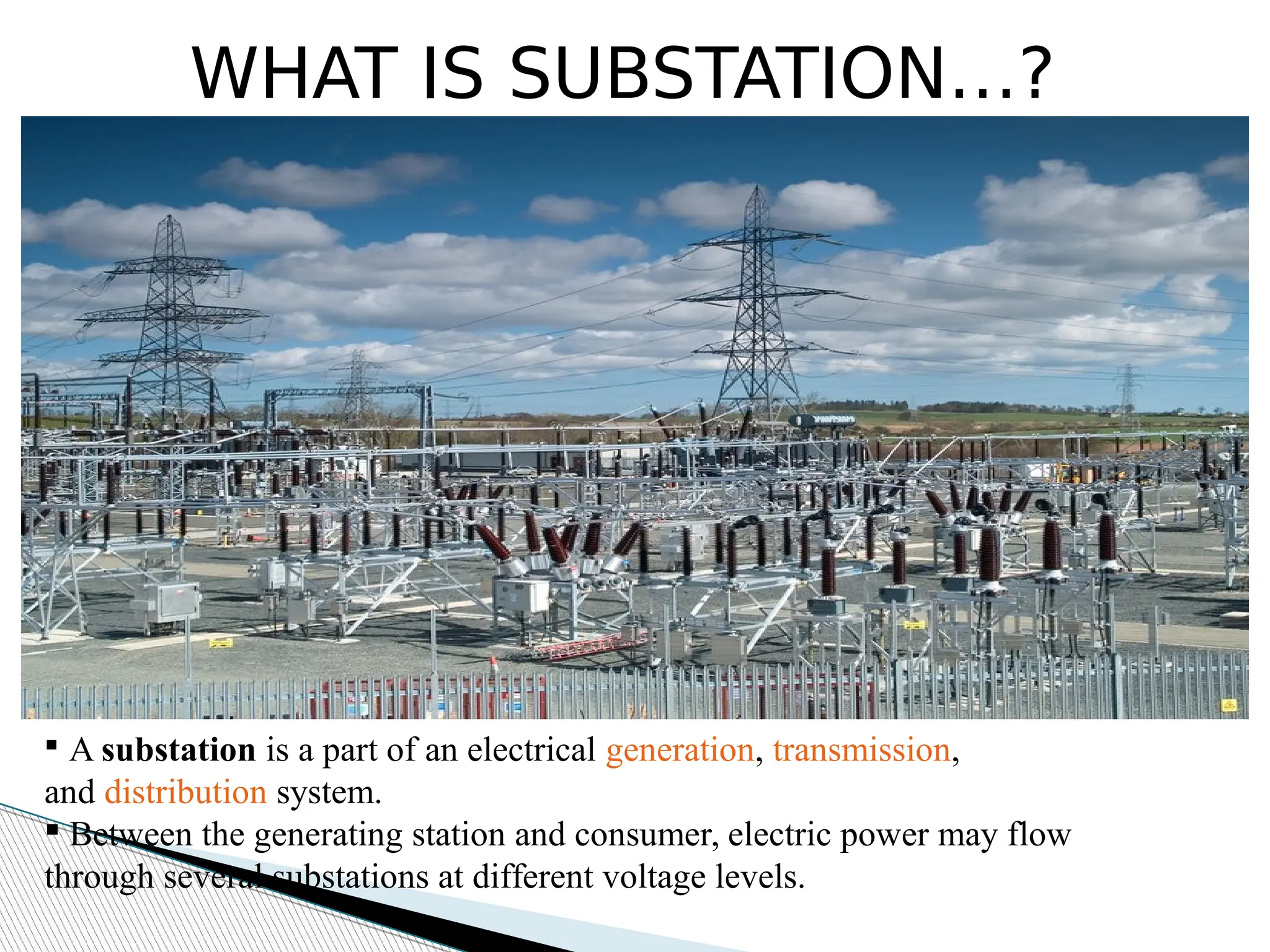
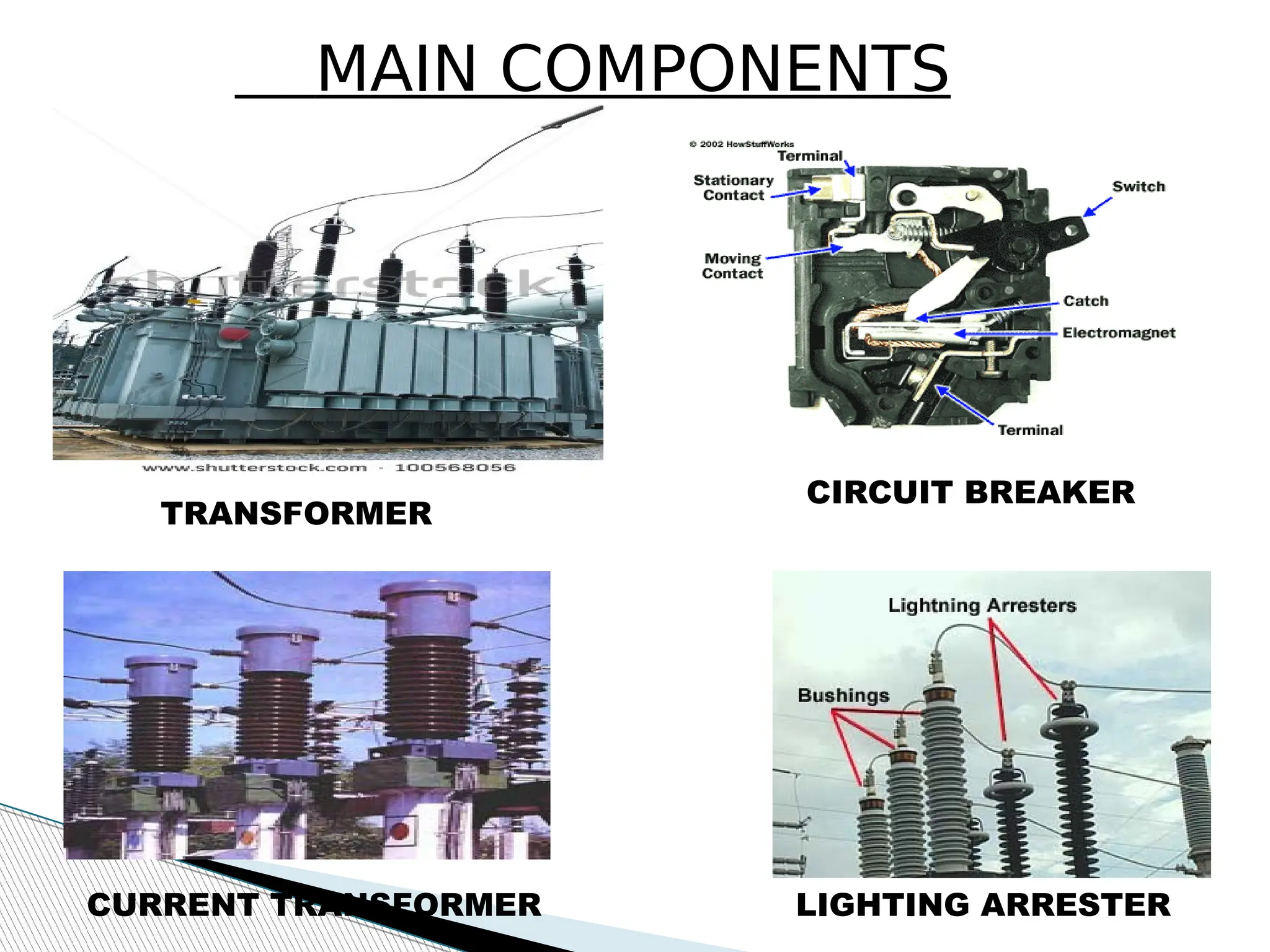
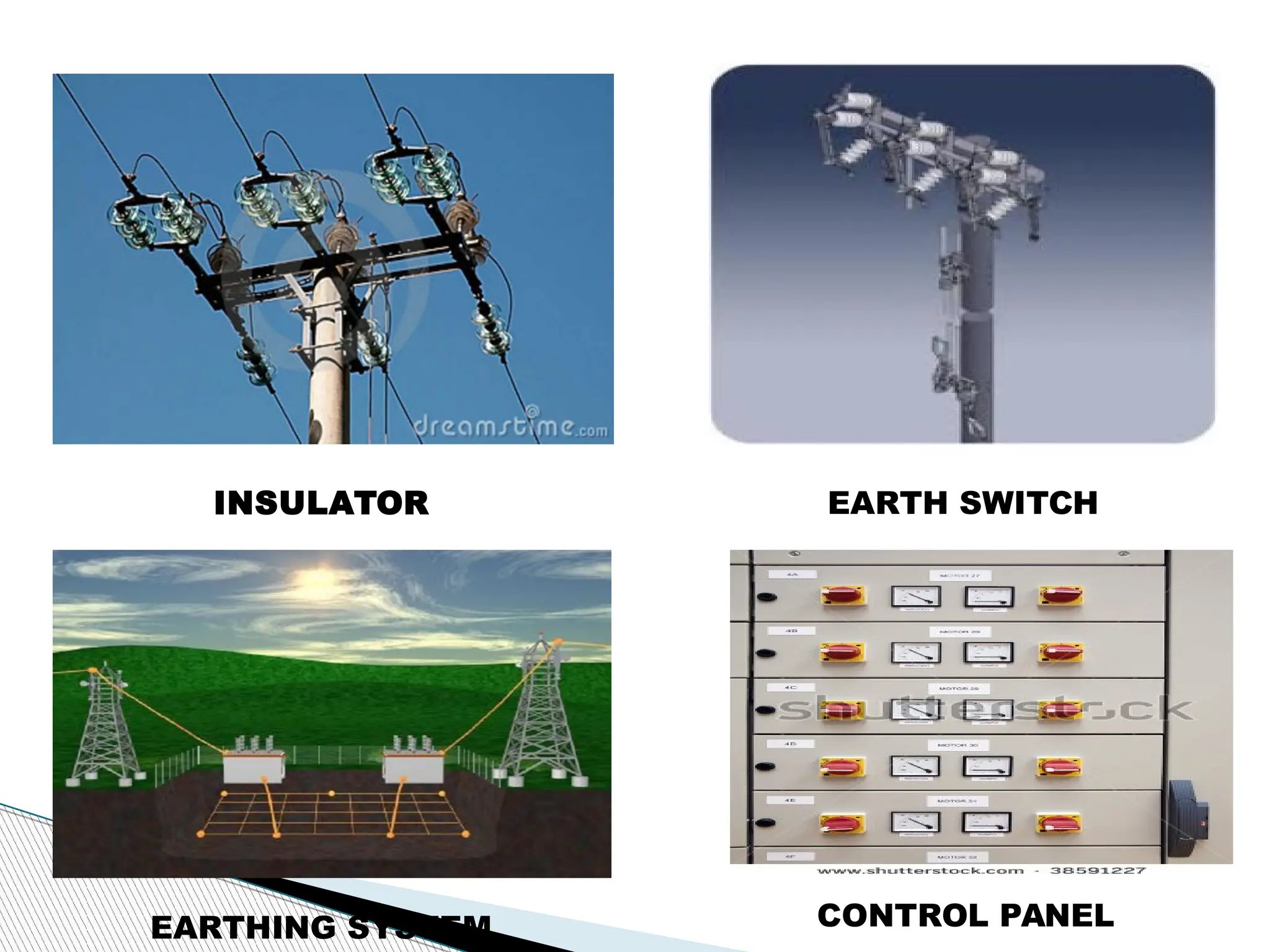
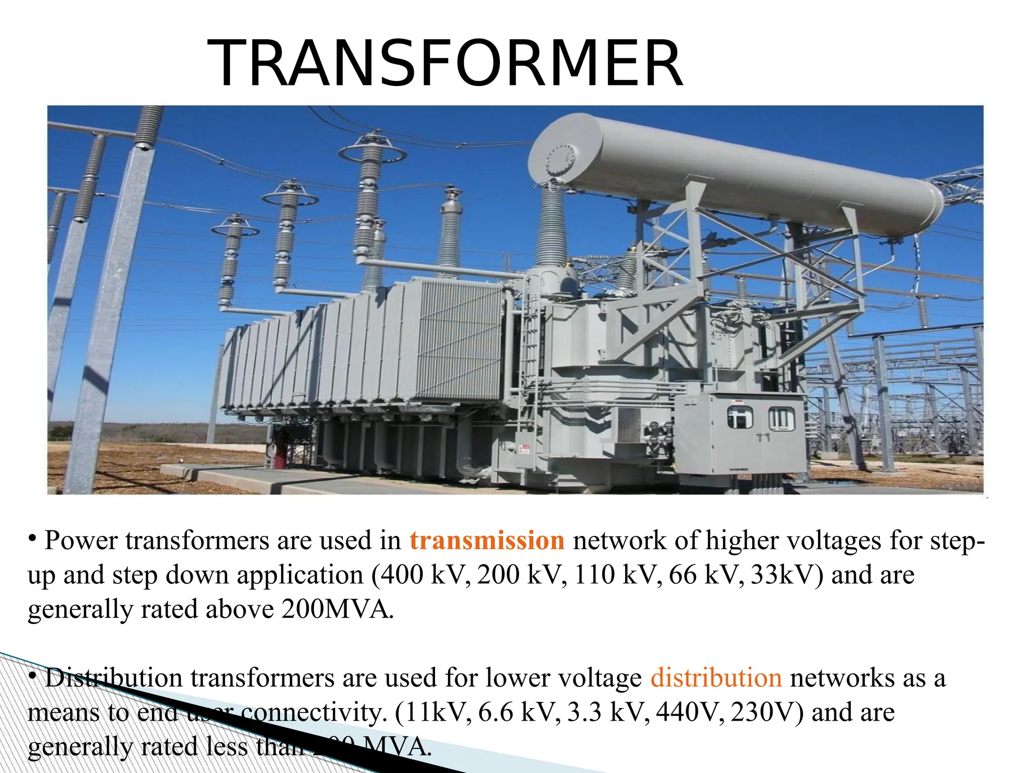
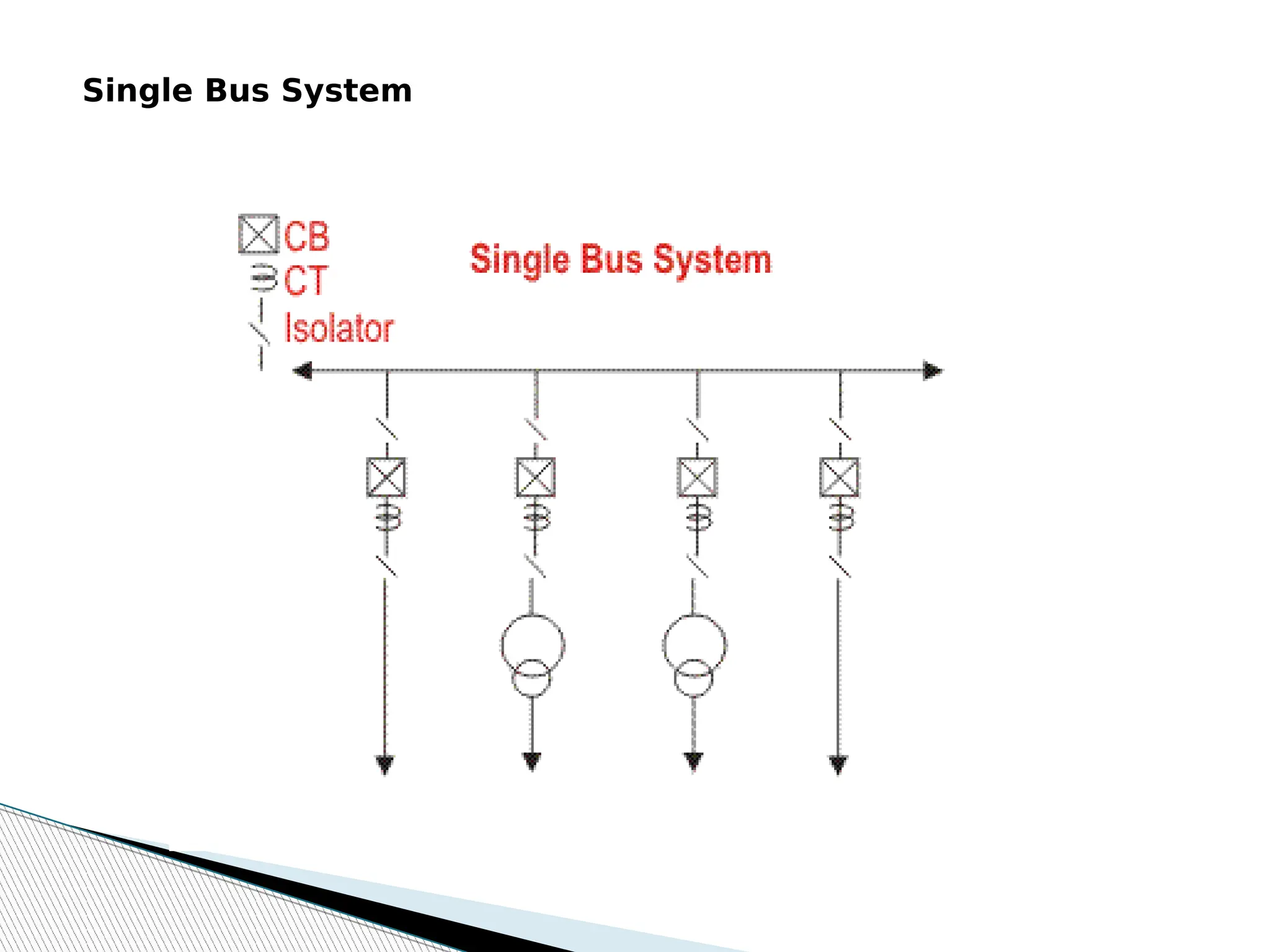
SUBSTATION
COMPONENTS
WHAT IS SUBSTATION…?
 A substation is a part of an electrical generation, transmission,
and distribution system.
 Between the generating station and consumer, electric power may flow
through several substations at different voltage levels.
 Transmission substation
 Distribution substation
 Converter substations
 Switching substation
 Classification by insulation
 Classification by structure
CLASSIFICATION
MAIN COMPONENTS
TRANSFORMER
CIRCUIT BREAKER
LIGHTING ARRESTER
CURRENT TRANSFORMER
BUS BAR ISOLATOR
POTENTIAL WAVE TRAP
INSULATOR EARTH SWITCH
EARTHING SYSTEM CONTROL PANEL
TRANSFORMER
• Power transformers are used in transmission network of higher voltages for step-
up and step down application (400 kV, 200 kV, 110 kV, 66 kV, 33kV) and are
generally rated above 200MVA.
• Distribution transformers are used for lower voltage distribution networks as a
means to end user connectivity. (11kV, 6.6 kV, 3.3 kV, 440V, 230V) and are
generally rated less than 200 MVA.
BUS BARS
• a bus bar is a thick strip of copper or aluminium that conducts electricity.
• Bus bars are used to carry very large currents, or to distribute current to
multiple devices within switchgear or equipment.
CIRCUIT BREAKER
•It designed to protect an electrical
circuit from damage caused by
overload or short circuit.
•Its basic function is to detect a fault
condition and discontinue the
electric flow
.
BULK OIL CB MINIMUM OIL AIR BLAST
AUXIAL BLAST CROSS BLAST SF 6
1. Actuator lever - used to manually
trip and reset the circuit breaker.
2. Actuator mechanism - forces the
contacts together or apart
3. Contacts - Allow current when
touching and break the current when
moved apart
4. Terminals
5. Bimetallic strip.
6. Calibration screw - allows the
manufacturer to precisely adjust the
trip current of the device after
assembly.
7. Solenoid
8. Arc divider/extinguisher
CIRCUIT BREAKER
ISOLATOR
•It is a disconnection
switch and to be operated
on no load.
•It is used to make sure
that an electrical circuit can
be completely de-energized
for service or maintenance.
• It provide electrical
isolation of the equipment .
CURRENT TRANSFORMER
•CT is a type of instrument transformer
that is used in power system for
measurement, detection, protection of the
system.
•Current transformers are used extensively
for measuring current and monitoring the
operation of the power grid.
POTENTIAL TRANSFORMER
 Potential transformers are instrument
transformers. They have a large number of
primary turns and a few number of
secondary turns.
 It converts voltages from high to low. It
will take the thousands of volts behind
power transmission systems and step the
voltage down to something that meters can
handle.
LIGHTING ARRESTER
It discharge the over voltage surges to earth
and protect the equipment insulation from
switching surges and lightning surges.
It located at the starting of the substation as
seen from incoming transmission lines and is
the first equipment of the substation
INSULATOR
 An insulator, also called a dielectric,
is a material that resists the flow of
electric current.
Insulators are used in electrical
equipment to support and separate
electrical conductors without allowing
current through themselves.
PIN TYPE SUSPENSION TYPE STRAIN TYPE
STRAIN TYPE SHACKLE TYPE
WAVE TRAP
 It trap the high frequency communication
signals sent on the line from the remote
substation and diverting them to the telecom/
teleprotection panel in the substation control
room .
 The Line trap offers high impedance to the
high frequency communication signals thus
obstructs the flow of these signals in to the
substation bus bars.
 The signals are primarily teleprotection
signals and in addition, voice and data
communication signals.
EARTH SWITCH
 Earth Switch is used to discharge the voltage on the circuit to
the earth for safety.
 Earth switch is mounted on the frame of the isolators.
 Earth Switch is located for each incomer transmission line and
each side of the bus-bar section
EARTHING SYSTEM
 Station Earthing System includes Earth Mat and Earth electrodes
placed below ground level
Function earthing system is to provide low resistance earthing for
 Discharging currents from the surge arresters, overhead shielding,
earthing switches
 For equipment body earthing
 For safe touch potential and step potential in substation.
METERING, CONTROL AND
RELAY PANELS
To house various measuring Instruments, control Instruments, Protective relays.
They are located in air-conditioned building. Control Cables are laid between
Switchyard equipment and these panels.
Some very commonly used bus bar arrangement are discussed
below
Single Bus System
Single Bus System is simplest and cheapest one. In this scheme all
the feeders and transformer bay are connected to only one single
bus as show.
Advantages of Single Bus System
1) This is very simple in design.
2) This is very cost effective scheme.
3) This is very convenient to operate.
Bus bar arrangements
Single Bus System
Disadvantages of Single Bus System
1) One but major difficulty of these type of
arrangement is that, maintenance of equipment
of any bay cannot be possible without
interrupting the feeder or transformer connected
to that bay.
2) The indoor 11KV switchboards have quite often
single bus bar arrangement.
Single Bus System with Bus
Sectionalizer
Some advantages are realized if a
single bus bar is sectionalized with
circuit breaker. If there are more than
one incoming and the incoming sources
and outgoing feeders are evenly
distributed on the sections as shown in
the figure, interruption of system can be
reduced to a good extent.
Single Bus System with Bus
Sectionalizer
Advantages of Single
Bus System with Bus
Sectionalizer
If any of the sources is out of system, still all
loads can be fed by switching on the
sectional circuit breaker or bus coupler breaker.
If one section of the bus bar system is under
maintenance, part load of the substation can be
fed by energizing the other section of bus bar.
Disadvantages of Single
Bus System with Bus
Sectionalizer
1) As in the case of single bus system,
maintenance of equipment of any bay cannot
be possible without interrupting the feeder or
transformer connected to that bay.
2) The use of isolator for bus sectionalizing
does not fulfill the purpose. The isolators
have to be operated ‘off circuit’ and which is
not possible without total interruption of bus
– bar. So investment for bus-coupler breaker
is required.
Double Bus System
1) In double bus bar system two identical bus bars
are used in such a way that any outgoing or
incoming feeder can be taken from any of the bus.
2)Actually every feeder is connected to both of the
buses in parallel through individual isolator as shown
in the figure.
By closing any of the isolators one can put the
feeder to associated bus. Both of the buses are
energized and total feeders are divided into two
groups, one group is fed from one bus and other
from other bus. But any feeder at any time can be
transferred from one bus to other. There is one bus
coupler breaker which should be kept close during
bus transfer operation. For transfer operation, one
should first close the bus coupler circuit
breaker then close the isolator associated with the
bus to where the feeder would be transferred and
then open the isolator associated with the bus from
where feeder is transferred. Lastly after this transfer
operation he or she should open the bus coupler
breaker.
Advantages of Double Bus System
Double Bus Bar Arrangement increases the
flexibility of system.
Disadvantages of Double Bus System
The arrangement does not permit breaker
maintenance with out interruption.
Double Breaker Bus System
In double breaker bus bar system two identical bus bars are
used in such a way that any outgoing or incoming feeder can
be taken from any of the bus similar to double bus bar system.
Only difference is that here every feeder is connected to both
of the buses in parallel through individual breaker instead only
isolator as shown in the figure. By closing any of the breakers
and its associated isolators, one can put the feeder to
respective bus. Both of the buses are energized and total
feeders are divided into two groups, one group is fed from one
bus and other from other bus similar to previous case. But any
feeder at any time can be transferred from one bus to other.
There is no need of bus coupler as because the operation is
done by breakers instead of isolator. For transfer operation,
one should first close the isolators and then the breaker
associated with the bus to where the feeder would be
transferred and then he or she opens the breaker and then
isolators associated with the bus from where feeder is
One and A Half Breaker Bus System
This is an improvement on the double breaker scheme to effect
saving in the number of circuit breakers. For every two circuits
only one spare breaker is provided. The protection is however
complicated since it must associate the central breaker with the
feeder whose own breaker is taken out for maintenance. For the
reasons given under double breaker scheme and because of the
prohibitory costs of equipment even this scheme is not much
popular. As shown in the figure that it is a simple design, two
feeders are fed from two different buses through their
associated breakers and these two feeders are coupled by a
third breaker which is called tie breaker. Normally all the three
breakers are closed and power is fed to both the circuits from
two buses which are operated in parallel. The tie breaker acts as
coupler for the two feeder circuits.
During failure of any feeder breaker, the power is fed through
the breaker of the second feeder and tie breaker, therefore each
feeder breaker has to be rated to feed both the feeders, coupled
by tie breaker.
Advantages of One and A Half Breaker Bus
System
During any fault on any one of the buses, that
faulty bus will be cleared instantly without
interrupting any feeders in the system since all
feeders will continue to feed from other healthy
bus.
Disadvantages of One and A Half Breaker
Bus System
This scheme is much expensive due to investment
for third breaker.
Main and Transfer Bus System
This is an alternative of double bus system. The main conception
of Main and Transfer Bus System is, here every feeder line is
directly connected through an isolator to a second bus called
transfer bus. The said isolator in between transfer bus and
feeder line is generally called bypass isolator. The main bus is as
usual connected to each feeder through a bay consists of circuit
breaker and associated isolators at both side of the breaker.
There is one bus coupler bay which couples transfer bus and
main bus through a circuit breaker and associated isolators at
both sides of the breaker. If necessary the transfer bus can be
energized by main bus power by closing the transfer bus coupler
isolators and then breaker. Then the power in transfer bus can
directly be fed to the feeder line by closing the bypass isolator. If
the main circuit breaker associated with feeder is switched off or
isolated from system, the feeder can still be fed in this way by
transferring it to transfer bus.
Switching Operation for Transferring a Feeder to Transfer Bus
from Main Bus without Interruption of Power
(i) First close the isolators at both side of the bus coupler breaker.
(ii) Then close the bypass isolator of the feeder which is to be transferred
to transfer bus.
(iii) Now energized the transfer bus by closing the bus coupler circuit
breaker from remote.
(iv) After bus coupler breaker is closed, now the power from main bus
flows to the feeder line through its main
breaker as well as bus coupler breaker via transfer bus.
(v) Now if main breaker of the feeder is switched off, total power flow will
instantaneously shift to the bus coupler breaker and hence this breaker
will serve the purpose of protection for the feeder.
(vi) At last the operating personnel open the isolators at both sides of the
main circuit breaker to make it isolated from rest of the live system.
So it can be concluded that in Main & Transfer Bus System the
maintenance of circuit breaker is possible without any interruption of
power. Because of this advantage the scheme is very popular for 33KV
and 13KV system.
Double Bus System with Bypass
Isolators
This is combination of the double bus system and
main and transfer bus system. In Double Bus System
with Bypass Isolators either bus can act as main bus
and second bus as transfer bus. It permits breaker
maintenance without interruption of power which is
not possible in double bus system but it provides all
the advantages of double bus system. It however
requires one additional isolator (bypass isolator) for
each feeder circuit and introduces slight
complication in system layout. Still this scheme is
best for optimum economy of system and it is best
optimum choice for 220KV system.
Ring Bus System
The schematic diagram of the system is given in the
figure. It provides a double feed to each feeder
circuit, opening one breaker under maintenance or
otherwise does not affect supply to any feeder. But
this system has two major disadvantages. One as it
is closed circuit system it is next to impossible to
extend in future and hence it is unsuitable for
developing system. Secondly, during maintenance
or any other reason if any one of the circuit
breaker in ring loop is switch of reliability of system
becomes very poor as because closed loop becomes
opened. Since, at that moment for any tripping of
any breaker in the open loop causes interruption in
all the feeders between tripped breaker and open
end of the loop.
220/33 KV GIS SUBSTATION COMPONENTS ppt.pdf

220/33 KV GIS SUBSTATION COMPONENTS ppt.pdf

  • 1.
  • 2.
    WHAT IS SUBSTATION…? A substation is a part of an electrical generation, transmission, and distribution system.  Between the generating station and consumer, electric power may flow through several substations at different voltage levels.
  • 3.
     Transmission substation Distribution substation  Converter substations  Switching substation  Classification by insulation  Classification by structure CLASSIFICATION
  • 4.
  • 5.
  • 6.
    INSULATOR EARTH SWITCH EARTHINGSYSTEM CONTROL PANEL
  • 7.
    TRANSFORMER • Power transformersare used in transmission network of higher voltages for step- up and step down application (400 kV, 200 kV, 110 kV, 66 kV, 33kV) and are generally rated above 200MVA. • Distribution transformers are used for lower voltage distribution networks as a means to end user connectivity. (11kV, 6.6 kV, 3.3 kV, 440V, 230V) and are generally rated less than 200 MVA.
  • 8.
    BUS BARS • abus bar is a thick strip of copper or aluminium that conducts electricity. • Bus bars are used to carry very large currents, or to distribute current to multiple devices within switchgear or equipment.
  • 9.
    CIRCUIT BREAKER •It designedto protect an electrical circuit from damage caused by overload or short circuit. •Its basic function is to detect a fault condition and discontinue the electric flow .
  • 10.
    BULK OIL CBMINIMUM OIL AIR BLAST AUXIAL BLAST CROSS BLAST SF 6
  • 11.
    1. Actuator lever- used to manually trip and reset the circuit breaker. 2. Actuator mechanism - forces the contacts together or apart 3. Contacts - Allow current when touching and break the current when moved apart 4. Terminals 5. Bimetallic strip. 6. Calibration screw - allows the manufacturer to precisely adjust the trip current of the device after assembly. 7. Solenoid 8. Arc divider/extinguisher CIRCUIT BREAKER
  • 12.
    ISOLATOR •It is adisconnection switch and to be operated on no load. •It is used to make sure that an electrical circuit can be completely de-energized for service or maintenance. • It provide electrical isolation of the equipment .
  • 13.
    CURRENT TRANSFORMER •CT isa type of instrument transformer that is used in power system for measurement, detection, protection of the system. •Current transformers are used extensively for measuring current and monitoring the operation of the power grid.
  • 14.
    POTENTIAL TRANSFORMER  Potentialtransformers are instrument transformers. They have a large number of primary turns and a few number of secondary turns.  It converts voltages from high to low. It will take the thousands of volts behind power transmission systems and step the voltage down to something that meters can handle.
  • 15.
    LIGHTING ARRESTER It dischargethe over voltage surges to earth and protect the equipment insulation from switching surges and lightning surges. It located at the starting of the substation as seen from incoming transmission lines and is the first equipment of the substation
  • 16.
    INSULATOR  An insulator,also called a dielectric, is a material that resists the flow of electric current. Insulators are used in electrical equipment to support and separate electrical conductors without allowing current through themselves.
  • 17.
    PIN TYPE SUSPENSIONTYPE STRAIN TYPE STRAIN TYPE SHACKLE TYPE
  • 18.
    WAVE TRAP  Ittrap the high frequency communication signals sent on the line from the remote substation and diverting them to the telecom/ teleprotection panel in the substation control room .  The Line trap offers high impedance to the high frequency communication signals thus obstructs the flow of these signals in to the substation bus bars.  The signals are primarily teleprotection signals and in addition, voice and data communication signals.
  • 19.
    EARTH SWITCH  EarthSwitch is used to discharge the voltage on the circuit to the earth for safety.  Earth switch is mounted on the frame of the isolators.  Earth Switch is located for each incomer transmission line and each side of the bus-bar section
  • 20.
    EARTHING SYSTEM  StationEarthing System includes Earth Mat and Earth electrodes placed below ground level Function earthing system is to provide low resistance earthing for  Discharging currents from the surge arresters, overhead shielding, earthing switches  For equipment body earthing  For safe touch potential and step potential in substation.
  • 21.
    METERING, CONTROL AND RELAYPANELS To house various measuring Instruments, control Instruments, Protective relays. They are located in air-conditioned building. Control Cables are laid between Switchyard equipment and these panels.
  • 22.
    Some very commonlyused bus bar arrangement are discussed below Single Bus System Single Bus System is simplest and cheapest one. In this scheme all the feeders and transformer bay are connected to only one single bus as show. Advantages of Single Bus System 1) This is very simple in design. 2) This is very cost effective scheme. 3) This is very convenient to operate. Bus bar arrangements
  • 23.
  • 24.
    Disadvantages of SingleBus System 1) One but major difficulty of these type of arrangement is that, maintenance of equipment of any bay cannot be possible without interrupting the feeder or transformer connected to that bay. 2) The indoor 11KV switchboards have quite often single bus bar arrangement.
  • 25.
    Single Bus Systemwith Bus Sectionalizer Some advantages are realized if a single bus bar is sectionalized with circuit breaker. If there are more than one incoming and the incoming sources and outgoing feeders are evenly distributed on the sections as shown in the figure, interruption of system can be reduced to a good extent.
  • 26.
    Single Bus Systemwith Bus Sectionalizer
  • 27.
    Advantages of Single BusSystem with Bus Sectionalizer If any of the sources is out of system, still all loads can be fed by switching on the sectional circuit breaker or bus coupler breaker. If one section of the bus bar system is under maintenance, part load of the substation can be fed by energizing the other section of bus bar.
  • 28.
    Disadvantages of Single BusSystem with Bus Sectionalizer 1) As in the case of single bus system, maintenance of equipment of any bay cannot be possible without interrupting the feeder or transformer connected to that bay. 2) The use of isolator for bus sectionalizing does not fulfill the purpose. The isolators have to be operated ‘off circuit’ and which is not possible without total interruption of bus – bar. So investment for bus-coupler breaker is required.
  • 29.
    Double Bus System 1)In double bus bar system two identical bus bars are used in such a way that any outgoing or incoming feeder can be taken from any of the bus. 2)Actually every feeder is connected to both of the buses in parallel through individual isolator as shown in the figure.
  • 31.
    By closing anyof the isolators one can put the feeder to associated bus. Both of the buses are energized and total feeders are divided into two groups, one group is fed from one bus and other from other bus. But any feeder at any time can be transferred from one bus to other. There is one bus coupler breaker which should be kept close during bus transfer operation. For transfer operation, one should first close the bus coupler circuit breaker then close the isolator associated with the bus to where the feeder would be transferred and then open the isolator associated with the bus from where feeder is transferred. Lastly after this transfer operation he or she should open the bus coupler breaker.
  • 32.
    Advantages of DoubleBus System Double Bus Bar Arrangement increases the flexibility of system. Disadvantages of Double Bus System The arrangement does not permit breaker maintenance with out interruption.
  • 33.
    Double Breaker BusSystem In double breaker bus bar system two identical bus bars are used in such a way that any outgoing or incoming feeder can be taken from any of the bus similar to double bus bar system. Only difference is that here every feeder is connected to both of the buses in parallel through individual breaker instead only isolator as shown in the figure. By closing any of the breakers and its associated isolators, one can put the feeder to respective bus. Both of the buses are energized and total feeders are divided into two groups, one group is fed from one bus and other from other bus similar to previous case. But any feeder at any time can be transferred from one bus to other. There is no need of bus coupler as because the operation is done by breakers instead of isolator. For transfer operation, one should first close the isolators and then the breaker associated with the bus to where the feeder would be transferred and then he or she opens the breaker and then isolators associated with the bus from where feeder is
  • 35.
    One and AHalf Breaker Bus System This is an improvement on the double breaker scheme to effect saving in the number of circuit breakers. For every two circuits only one spare breaker is provided. The protection is however complicated since it must associate the central breaker with the feeder whose own breaker is taken out for maintenance. For the reasons given under double breaker scheme and because of the prohibitory costs of equipment even this scheme is not much popular. As shown in the figure that it is a simple design, two feeders are fed from two different buses through their associated breakers and these two feeders are coupled by a third breaker which is called tie breaker. Normally all the three breakers are closed and power is fed to both the circuits from two buses which are operated in parallel. The tie breaker acts as coupler for the two feeder circuits. During failure of any feeder breaker, the power is fed through the breaker of the second feeder and tie breaker, therefore each feeder breaker has to be rated to feed both the feeders, coupled by tie breaker.
  • 37.
    Advantages of Oneand A Half Breaker Bus System During any fault on any one of the buses, that faulty bus will be cleared instantly without interrupting any feeders in the system since all feeders will continue to feed from other healthy bus. Disadvantages of One and A Half Breaker Bus System This scheme is much expensive due to investment for third breaker.
  • 38.
    Main and TransferBus System This is an alternative of double bus system. The main conception of Main and Transfer Bus System is, here every feeder line is directly connected through an isolator to a second bus called transfer bus. The said isolator in between transfer bus and feeder line is generally called bypass isolator. The main bus is as usual connected to each feeder through a bay consists of circuit breaker and associated isolators at both side of the breaker. There is one bus coupler bay which couples transfer bus and main bus through a circuit breaker and associated isolators at both sides of the breaker. If necessary the transfer bus can be energized by main bus power by closing the transfer bus coupler isolators and then breaker. Then the power in transfer bus can directly be fed to the feeder line by closing the bypass isolator. If the main circuit breaker associated with feeder is switched off or isolated from system, the feeder can still be fed in this way by transferring it to transfer bus.
  • 40.
    Switching Operation forTransferring a Feeder to Transfer Bus from Main Bus without Interruption of Power (i) First close the isolators at both side of the bus coupler breaker. (ii) Then close the bypass isolator of the feeder which is to be transferred to transfer bus. (iii) Now energized the transfer bus by closing the bus coupler circuit breaker from remote. (iv) After bus coupler breaker is closed, now the power from main bus flows to the feeder line through its main breaker as well as bus coupler breaker via transfer bus. (v) Now if main breaker of the feeder is switched off, total power flow will instantaneously shift to the bus coupler breaker and hence this breaker will serve the purpose of protection for the feeder. (vi) At last the operating personnel open the isolators at both sides of the main circuit breaker to make it isolated from rest of the live system. So it can be concluded that in Main & Transfer Bus System the maintenance of circuit breaker is possible without any interruption of power. Because of this advantage the scheme is very popular for 33KV and 13KV system.
  • 41.
    Double Bus Systemwith Bypass Isolators
  • 42.
    This is combinationof the double bus system and main and transfer bus system. In Double Bus System with Bypass Isolators either bus can act as main bus and second bus as transfer bus. It permits breaker maintenance without interruption of power which is not possible in double bus system but it provides all the advantages of double bus system. It however requires one additional isolator (bypass isolator) for each feeder circuit and introduces slight complication in system layout. Still this scheme is best for optimum economy of system and it is best optimum choice for 220KV system.
  • 43.
    Ring Bus System Theschematic diagram of the system is given in the figure. It provides a double feed to each feeder circuit, opening one breaker under maintenance or otherwise does not affect supply to any feeder. But this system has two major disadvantages. One as it is closed circuit system it is next to impossible to extend in future and hence it is unsuitable for developing system. Secondly, during maintenance or any other reason if any one of the circuit breaker in ring loop is switch of reliability of system becomes very poor as because closed loop becomes opened. Since, at that moment for any tripping of any breaker in the open loop causes interruption in all the feeders between tripped breaker and open end of the loop.