2
Interrupts
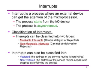
• Interrupt isa process where an external device
can get the attention of the microprocessor.
– The process starts from the I/O device
– The process is asynchronous.
• Classification of Interrupts
– Interrupts can be classified into two types:
• Maskable Interrupts (Can be delayed or Rejected)
• Non-Maskable Interrupts (Can not be delayed or
Rejected)
• Interrupts can also be classified into:
• Vectored (the address of the service routine is hard-wired)
• Non-vectored (the address of the service routine needs to be
supplied externally by the device)
3.
3
Interrupts
• An interruptis considered to be an emergency
signal that may be serviced.
– The Microprocessor may respond to it as soon as
possible.
• What happens when MP is interrupted ?
– When the Microprocessor receives an interrupt
signal, it suspends the currently executing
program and jumps to an Interrupt Service Routine
(ISR) to respond to the incoming interrupt.
– Each interrupt will most probably have its own
ISR.
4.
4
Responding to Interrupts
•Responding to an interrupt may be immediate or
delayed depending on whether the interrupt is
maskable or non-maskable and whether
interrupts are being masked or not.
• There are two ways of redirecting the execution
to the ISR depending on whether the interrupt is
vectored or non-vectored.
– Vectored: The address of the subroutine is already
known to the Microprocessor
– Non Vectored: The device will have to supply the
address of the subroutine to the Microprocessor
5.
5
The 8085 Interrupts
•When a device interrupts, it actually wants the
MP to give a service which is equivalent to asking
the MP to call a subroutine. This subroutine is
called ISR (Interrupt Service Routine)
• The ‘EI’ instruction is a one byte instruction and is
used to Enable the non-maskable interrupts.
• The ‘DI’ instruction is a one byte instruction and is
used to Disable the non-maskable interrupts.
• The 8085 has a single Non-Maskable interrupt.
– The non-maskable interrupt is not affected by the
value of the Interrupt Enable flip flop.
6.
6
The 8085 Interrupts
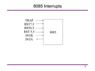
•The 8085 has 5 interrupt inputs.
– The INTR input.
• The INTR input is the only non-vectored interrupt.
• INTR is maskable using the EI/DI instruction pair.
– RST 5.5, RST 6.5, RST 7.5 are all automatically
vectored.
• RST 5.5, RST 6.5, and RST 7.5 are all maskable.
– TRAP is the only non-maskable interrupt in the
8085
• TRAP is also automatically vectored
7.
7
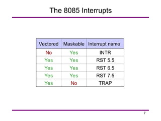
The 8085 Interrupts
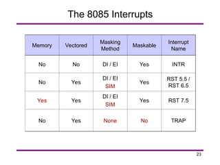
Interruptname
Maskable
Vectored
INTR
Yes
No
RST 5.5
Yes
Yes
RST 6.5
Yes
Yes
RST 7.5
Yes
Yes
TRAP
No
Yes
9
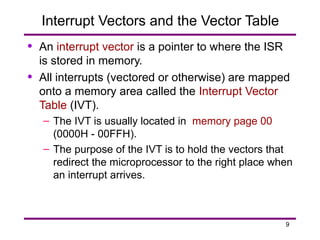
Interrupt Vectors andthe Vector Table
• An interrupt vector is a pointer to where the ISR
is stored in memory.
• All interrupts (vectored or otherwise) are mapped
onto a memory area called the Interrupt Vector
Table (IVT).
– The IVT is usually located in memory page 00
(0000H - 00FFH).
– The purpose of the IVT is to hold the vectors that
redirect the microprocessor to the right place when
an interrupt arrives.
10.
10
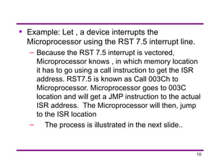
• Example: Let, a device interrupts the
Microprocessor using the RST 7.5 interrupt line.
– Because the RST 7.5 interrupt is vectored,
Microprocessor knows , in which memory location
it has to go using a call instruction to get the ISR
address. RST7.5 is known as Call 003Ch to
Microprocessor. Microprocessor goes to 003C
location and will get a JMP instruction to the actual
ISR address. The Microprocessor will then, jump
to the ISR location
– The process is illustrated in the next slide..
11.
11
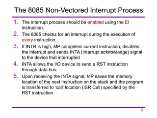
1. The interruptprocess should be enabled using the EI
instruction.
2. The 8085 checks for an interrupt during the execution of
every instruction.
3. If INTR is high, MP completes current instruction, disables
the interrupt and sends INTA (Interrupt acknowledge) signal
to the device that interrupted
4. INTA allows the I/O device to send a RST instruction
through data bus.
5. Upon receiving the INTA signal, MP saves the memory
location of the next instruction on the stack and the program
is transferred to ‘call’ location (ISR Call) specified by the
RST instruction
The 8085 Non-Vectored Interrupt Process
12.
12
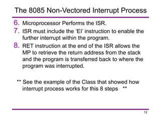
6. Microprocessor Performsthe ISR.
7. ISR must include the ‘EI’ instruction to enable the
further interrupt within the program.
8. RET instruction at the end of the ISR allows the
MP to retrieve the return address from the stack
and the program is transferred back to where the
program was interrupted.
** See the example of the Class that showed how
interrupt process works for this 8 steps **
The 8085 Non-Vectored Interrupt Process
13.
13
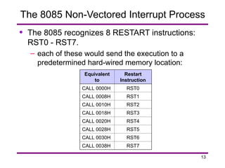
The 8085 Non-VectoredInterrupt Process
• The 8085 recognizes 8 RESTART instructions:
RST0 - RST7.
– each of these would send the execution to a
predetermined hard-wired memory location:
Restart
Instruction
Equivalent
to
RST0
CALL 0000H
RST1
CALL 0008H
RST2
CALL 0010H
RST3
CALL 0018H
RST4
CALL 0020H
RST5
CALL 0028H
RST6
CALL 0030H
RST7
CALL 0038H
14.
14
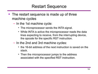
Restart Sequence
• Therestart sequence is made up of three
machine cycles
– In the 1st machine cycle:
• The microprocessor sends the INTA signal.
• While INTA is active the microprocessor reads the data
lines expecting to receive, from the interrupting device,
the opcode for the specific RST instruction.
– In the 2nd and 3rd machine cycles:
• the 16-bit address of the next instruction is saved on the
stack.
• Then the microprocessor jumps to the address
associated with the specified RST instruction.
15.
15
Multiple Interrupts &Priorities
• How do we allow multiple devices to interrupt
using the INTR line?
– The microprocessor can only respond to one
signal on INTR at a time.
– Therefore, we must allow the signal from only one
of the devices to reach the microprocessor.
– We must assign some priority to the different
devices and allow their signals to reach the
microprocessor according to the priority.
16.
16
The Priority Encoder
•The solution is to use a circuit called the priority
encoder (74LS148).
– This circuit has 8 inputs and 3 outputs.
– The inputs are assigned increasing priorities
according to the increasing index of the input.
• Input 7 has highest priority and input 0 has the lowest.
– The 3 outputs carry the index of the highest
priority active input.
17.
17
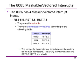
The 8085 Maskable/VectoredInterrupts
• The 8085 has 4 Masked/Vectored interrupt
inputs.
– RST 5.5, RST 6.5, RST 7.5
• They are all maskable.
• They are automatically vectored according to the
following table:
– The vectors for these interrupt fall in between the vectors
for the RST instructions. That’s why they have names like
RST 5.5 (RST 5 and a half).
Interrupt
Vector
RST 5.5
002CH
RST 6.5
0034H
RST 7.5
003CH
18.
18
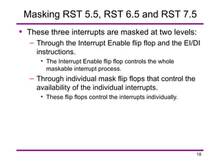
Masking RST 5.5,RST 6.5 and RST 7.5
• These three interrupts are masked at two levels:
– Through the Interrupt Enable flip flop and the EI/DI
instructions.
• The Interrupt Enable flip flop controls the whole
maskable interrupt process.
– Through individual mask flip flops that control the
availability of the individual interrupts.
• These flip flops control the interrupts individually.
19.
19
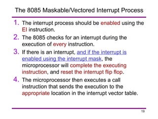
The 8085 Maskable/VectoredInterrupt Process
1. The interrupt process should be enabled using the
EI instruction.
2. The 8085 checks for an interrupt during the
execution of every instruction.
3. If there is an interrupt, and if the interrupt is
enabled using the interrupt mask, the
microprocessor will complete the executing
instruction, and reset the interrupt flip flop.
4. The microprocessor then executes a call
instruction that sends the execution to the
appropriate location in the interrupt vector table.
20.
20
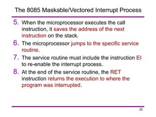
The 8085 Maskable/VectoredInterrupt Process
5. When the microprocessor executes the call
instruction, it saves the address of the next
instruction on the stack.
6. The microprocessor jumps to the specific service
routine.
7. The service routine must include the instruction EI
to re-enable the interrupt process.
8. At the end of the service routine, the RET
instruction returns the execution to where the
program was interrupted.
21.
21
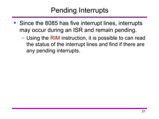
Pending Interrupts
• Sincethe 8085 has five interrupt lines, interrupts
may occur during an ISR and remain pending.
– Using the RIM instruction, it is possible to can read
the status of the interrupt lines and find if there are
any pending interrupts.
22.
22
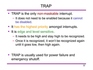
TRAP
• TRAP isthe only non-maskable interrupt.
– It does not need to be enabled because it cannot
be disabled.
• It has the highest priority amongst interrupts.
• It is edge and level sensitive.
– It needs to be high and stay high to be recognized.
– Once it is recognized, it won’t be recognized again
until it goes low, then high again.
• TRAP is usually used for power failure and
emergency shutoff.