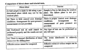
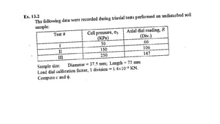
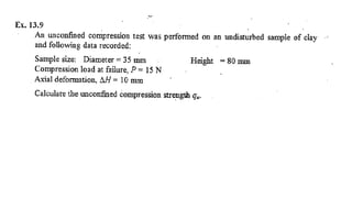
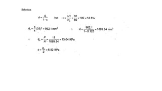
Shear Strength
Direct shear test
Preparation of a sand specimen
Components of the shear box Preparation of a sand specimen
Porous
plates
Direct shear test is most suitable for consolidated drained tests
specially on granular soils (e.g.: sand) or stiff clays
Direct shear test
Leveling the top surface
of specimen
Preparation of a sand specimen
Specimen preparation
completed
Pressure plate
Direct shear test
Test procedure
Porous
plates
Pressure plate
Steel ball
Step 1: Apply a vertical load to the specimen and wait for consolidation
P
Proving ring
to measure
shear force
S
Direct shear test
Step 2: Lower box is subjected to a horizontal displacement at a constant rate
Step 1: Apply a vertical load to the specimen and wait for consolidation
PTest procedure
Pressure plate
Steel ball
Proving ring
to measure
shear force
S
Porous
plates
Direct shear test
Shear box
Loading frame to
apply vertical load
Dial gauge to
measure vertical
displacement
Dial gauge to
measure horizontal
displacement
Proving ring
to measure
shear force
Direct shear test
Analysis of test results
sampletheofsectioncrossofArea
(P)forceNormal
stressNormal ==
sampletheofsectioncrossofArea
(S)surfaceslidingat thedevelopedresistanceShear
stressShear ==
Note: Cross-sectional area of the sample changes with the horizontal
displacement
Direct shear tests on sands
Shearstress,
Shear displacement
Dense sand/
OC clay
f
Loose sand/
NC clayf
Dense sand/OC Clay
Loose sand/NC Clay
Changeinheight
ofthesample
ExpansionCompression
Shear displacement
Stress-strain relationship
f1
Normal stress = 1
Direct shear tests on sands
How to determine strength parameters c and f
Shearstress,
Shear displacement
f2
Normal stress = 2
f3
Normal stress = 3
Shearstressatfailure,f
Normal stress, 
f
Mohr – Coulomb failure envelope
Direct shear tests on sands
Some important facts on strength parameters c and f of sand
Sand is cohesionless
hence c = 0
Direct shear tests are
drained and pore water
pressures are
dissipated, hence u = 0
Therefore,
f’ = f and c’ = c = 0
Direct shear tests on clays
Failure envelopes for clay from drained direct shear testsShearstressatfailure,f
Normal force, 
f’
Normally consolidated clay (c’ = 0)
In case of clay, horizontal displacement should be applied at a very
slow rate to allow dissipation of pore water pressure (therefore, one
test would take several days to finish)
Overconsolidated clay (c’ ≠ 0)
Interface tests on direct shear apparatus
In many foundation design problems and retaining wall problems, it
is required to determine the angle of internal friction between soil
and the structural material (concrete, steel or wood)
 tan'+= af c
Where,
ca = adhesion,
 = angle of internal friction
Foundation material
Soil
P
S
Foundation material
Soil
P
S
Advantages of direct shear apparatus
❑ Due to the smaller thickness of the sample, rapid drainage can
be achieved
❑ Can be used to determine interface strength parameters
❑ Clay samples can be oriented along the plane of weakness or
an identified failure plane
Disadvantages of direct shear apparatus
❑ Failure occurs along a predetermined failure plane
❑ Area of the sliding surface changes as the test progresses
❑ Non-uniform distribution of shear stress along the failure surface
Triaxial Shear Test
Soil sample
at failure
Failure plane
Porous
stone
impervious
membrane
Piston (to apply deviatoric stress)
O-ring
pedestal
Perspex
cell
Cell pressure
Back pressure Pore pressure or
volume change
Water
Soil
sample
Triaxial Shear Test
Specimen preparation (undisturbed sample)
Sampling tubes
Sample extruder
Triaxial Shear Test
Specimen preparation (undisturbed sample)
Edges of the sample
are carefully trimmed
Setting up the sample
in the triaxial cell
Triaxial Shear Test
Sample is covered
with a rubber
membrane and sealed
Cell is completely
filled with water
Specimen preparation (undisturbed sample)
Triaxial Shear Test
Specimen preparation (undisturbed sample)
Proving ring to
measure the
deviator load
Dial gauge to
measure vertical
displacement
In some tests
Types of Triaxial Tests
Is the drainage valve open?
yes no
Consolidated
sample
Unconsolidated
sample
Is the drainage valve open?
yes no
Drained
loading
Undrained
loading
Under all-around cell pressure c
cc
c
cStep 1
deviatoric stress
( = q)
Shearing (loading)
Step 2
c c
c+ q
Types of Triaxial Tests
Is the drainage valve open?
yes no
Consolidated
sample
Unconsolidated
sample
Under all-around cell pressure c
Step 1
Is the drainage valve open?
yes no
Drained
loading
Undrained
loading
Shearing (loading)
Step 2
CD test
CU test
UU test
Deviator stress (q or d) = 1 – 3
Consolidated- drained test (CD Test)
1 = VC + 
3 = hC
Deviatorstress,d
Axial strain
Dense sand
or OC clay
(d)f
Dense sand
or OC clay
Loose sand
or NC clay
Volumechange
ofthesample
ExpansionCompression
Axial strain
Stress-strain relationship during shearing
Consolidated- drained test (CD Test)
Loose sand
or NC Clay(d)f
CD tests How to determine strength parameters c and f
Deviatorstress,d
Axial strain
Shearstress,
 or ’
f
Mohr – Coulomb
failure envelope
(d)fa
Confining stress = 3a(d)fb
Confining stress = 3b
(d)fc
Confining stress = 3c
3c 1c3a 1a
(d)fa
3b 1b
(d)fb
1 = 3 + (d)f
3
CD tests
Strength parameters c and f obtained from CD tests
Since u = 0 in CD
tests,  = ’
Therefore, c = c’
and f = f’
cd and fd are used
to denote them
CD tests Failure envelopes
Shearstress,
 or ’
fd
Mohr – Coulomb
failure envelope
3a 1a
(d)fa
For sand and NC Clay, cd = 0
Therefore, one CD test would be sufficient to determine fd
of sand or NC clay
CU tests How to determine strength parameters c and f
Deviatorstress,d
Axial strain
Shearstress,
 or ’
(d)fb
Confining stress = 3b
3b 1b3a 1a
(d)fa
fcuMohr – Coulomb
failure envelope in
terms of total stresses
ccu
1 = 3 + (d)f
3
Total stresses at failure
(d)fa
Confining stress = 3a
CU tests
Strength parameters c and f obtained from CD tests
Shear strength
parameters in terms
of total stresses are
ccu and fcu
Shear strength
parameters in terms
of effective stresses
are c’ and f’
c’ = cd and f’ = fd
Unconsolidated- Undrained test (UU Test)
Data analysis
C = 3
C = 3
No
drainage
Initial specimen condition
3 + d
3
No
drainage
Specimen condition
during shearing
Initial volume of the sample = A0 × H0
Volume of the sample during shearing = A × H
Since the test is conducted under undrained condition,
A × H = A0 × H0
A ×(H0 – H) = A0 × H0
A ×(1 – H/H0) = A0 z
A
A
−
=
1
0
Unconfined Compression Test (UC Test)
1 = VC + 
3 = 0
Confining pressure is zero in the UC test
Unconfined Compression Test (UC Test)
1 = VC + f
3 = 0
Shearstress,
Normal stress, 
qu
Note: Theoritically qu = cu , However in the actual case
qu < cu due to premature failure of the sample
In-situ shear tests
❑ Vane shear test
❑ Torvane
❑ Pocket Penetrometer
❑ Pressuremeter
❑ Static Cone Penetrometer test (Push
Cone Penetrometer Test, PCPT)
❑ Standard Penetration Test, SPT
In-situ shear tests
❑ Vane shear test (suitable for soft to stiff clays)
❑ Torvane
❑ Pocket Penetrometer
❑ Pressuremeter
❑ Static Cone Penetrometer test (Push
Cone Penetrometer Test, PCPT)
❑ Standard Penetration Test, SPT
PLAN VIEW
Vane shear test
This is one of the most versatile and widely used devices used for
investigating undrained shear strength (Cu) and sensitivity of soft clays
Bore hole
(diameter = DB)
h > 3DB)
Vane
D
H
Applied
Torque, T
Vane T
Rupture
surface
Disturbed
soil
Rate of rotation : 60 – 120 per minute
Test can be conducted at 0.5 m
vertical intervals
Vane shear test
Since the test is very fast,
Unconsolidated Undrained
(UU) can be expected
Cu
Cu
h
Vane shear test
Since the test is very fast,
Unconsolidated Undrained
(UU) can be expected
Cu
Cu
h
After the initial test, vane can be
rapidly rotated through several
revolutions until the clay become
remoulded
peak
ultimate

Shear displacement
StengthUltimate
StengthPeak
ySensitivit =
Some important facts on vane shear test
Insertion of vane into soft
clays and silts disrupts the
natural soil structure around
the vane causing reduction
of shear strength
The above reduction
is partially regained
after some time
Cu as determined by
vane shear test may
be a function of the
rate of angular
rotation of the vane
In-situ shear tests
❑ Vane shear test
❑ Torvane (suitable for very soft to stiff clays)
❑ Pocket Penetrometer
❑ Pressuremeter
❑ Static Cone Penetrometer test (Push
Cone Penetrometer Test, PCPT)
❑ Standard Penetration Test, SPT
Torvane
Torvane is a modification to the vane
In-situ shear tests
❑ Vane shear test
❑ Torvane
❑ Pocket Penetrometer (suitable for very soft to stiff clays)
❑ Pressuremeter
❑ Static Cone Penetrometer test (Push
Cone Penetrometer Test, PCPT)
❑ Standard Penetration Test, SPT
Pocket Penetrometer
Pushed directly into the soil. The unconfined compression
strength (qu) is measured by a calibrated spring.
Swedish Fall Cone (suitable for very soft to soft clays)
The test must be calibrated
Soil sample
Cu ∞ Mass of the cone
∞ 1/(penetration)2
In-situ shear tests
❑ Vane shear test
❑ Torvane
❑ Pocket Penetrometer
❑ Pressuremeter (suitable for all soil types)
❑ Static Cone Penetrometer test (Push
Cone Penetrometer Test, PCPT)
❑ Standard Penetration Test, SPT
Pressuremeter
Pre – bored or
self – bored hole
Guard cell
Measuring cell
Guard cell
Coaxial tube
Water
Air
In-situ shear tests
❑ Vane shear test
❑ Torvane
❑ Pocket Penetrometer
❑ Pressuremeter
❑ Static Cone Penetrometer test (Push
Cone Penetrometer Test, PCPT)
(suitable for all soil types except very course
granular materials)
❑ Standard Penetration Test, SPT
Static Cone
Penetrometer
test
Cone penetrometers
with pore water
pressure measurement
capability are known as
piezocones
40 mm
40 mm
40 mm
40 mm
Static Cone Penetrometer test
Force required for the inner rod to push the tip (Fc) and the
total force required to push both the tip and the sleeve (Fc +
Fs) will be measured
Point resistance (qc) = Fc/ area of the tip
Sleeve resistance (qs) = Fs/ area of the sleeve in contact with soil
Friction Ratio (fr) = qs/ qc ×100 (%)
Various correlations have been developed to determine soil
strength parameters (c, f, ect) from fr
In-situ shear tests
❑ Vane shear test
❑ Torvane
❑ Pocket Penetrometer
❑ Pressuremeter
❑ Static Cone Penetrometer test (Push
Cone Penetrometer Test, PCPT)
❑ Standard Penetration Test, SPT
(suitable for granular materials)
Standard Penetration Test, SPT
SPT is the most widely used test procedure to determine
the properties of in-situ soils
63.5 kg
0.76 m
Drill rod
0.15 m
0.15 m
0.15 m
Number of blows = N1
Number of blows = N2
Number of blows = N3
Standard penetration resistance (SPT N) = N2 + N3
Number of blows for the first 150 mm
penetration is disregarded due to the
disturbance likely to exist at the bottom
of the drill hole
The test can be conducted at every 1m
vertical intervals
Various correlations have been developed to determine soil
strength parameters (c, f, ect) from N
Standard Penetration Test, SPT
SPT (Manual operation)
1  shear strength
1  shear strength
1  shear strength

1 shear strength

  • 1.
  • 18.
    Direct shear test Preparationof a sand specimen Components of the shear box Preparation of a sand specimen Porous plates Direct shear test is most suitable for consolidated drained tests specially on granular soils (e.g.: sand) or stiff clays
  • 19.
    Direct shear test Levelingthe top surface of specimen Preparation of a sand specimen Specimen preparation completed Pressure plate
  • 20.
    Direct shear test Testprocedure Porous plates Pressure plate Steel ball Step 1: Apply a vertical load to the specimen and wait for consolidation P Proving ring to measure shear force S
  • 21.
    Direct shear test Step2: Lower box is subjected to a horizontal displacement at a constant rate Step 1: Apply a vertical load to the specimen and wait for consolidation PTest procedure Pressure plate Steel ball Proving ring to measure shear force S Porous plates
  • 22.
    Direct shear test Shearbox Loading frame to apply vertical load Dial gauge to measure vertical displacement Dial gauge to measure horizontal displacement Proving ring to measure shear force
  • 23.
    Direct shear test Analysisof test results sampletheofsectioncrossofArea (P)forceNormal stressNormal == sampletheofsectioncrossofArea (S)surfaceslidingat thedevelopedresistanceShear stressShear == Note: Cross-sectional area of the sample changes with the horizontal displacement
  • 24.
    Direct shear testson sands Shearstress, Shear displacement Dense sand/ OC clay f Loose sand/ NC clayf Dense sand/OC Clay Loose sand/NC Clay Changeinheight ofthesample ExpansionCompression Shear displacement Stress-strain relationship
  • 25.
    f1 Normal stress =1 Direct shear tests on sands How to determine strength parameters c and f Shearstress, Shear displacement f2 Normal stress = 2 f3 Normal stress = 3 Shearstressatfailure,f Normal stress,  f Mohr – Coulomb failure envelope
  • 26.
    Direct shear testson sands Some important facts on strength parameters c and f of sand Sand is cohesionless hence c = 0 Direct shear tests are drained and pore water pressures are dissipated, hence u = 0 Therefore, f’ = f and c’ = c = 0
  • 27.
    Direct shear testson clays Failure envelopes for clay from drained direct shear testsShearstressatfailure,f Normal force,  f’ Normally consolidated clay (c’ = 0) In case of clay, horizontal displacement should be applied at a very slow rate to allow dissipation of pore water pressure (therefore, one test would take several days to finish) Overconsolidated clay (c’ ≠ 0)
  • 28.
    Interface tests ondirect shear apparatus In many foundation design problems and retaining wall problems, it is required to determine the angle of internal friction between soil and the structural material (concrete, steel or wood)  tan'+= af c Where, ca = adhesion,  = angle of internal friction Foundation material Soil P S Foundation material Soil P S
  • 29.
    Advantages of directshear apparatus ❑ Due to the smaller thickness of the sample, rapid drainage can be achieved ❑ Can be used to determine interface strength parameters ❑ Clay samples can be oriented along the plane of weakness or an identified failure plane Disadvantages of direct shear apparatus ❑ Failure occurs along a predetermined failure plane ❑ Area of the sliding surface changes as the test progresses ❑ Non-uniform distribution of shear stress along the failure surface
  • 30.
    Triaxial Shear Test Soilsample at failure Failure plane Porous stone impervious membrane Piston (to apply deviatoric stress) O-ring pedestal Perspex cell Cell pressure Back pressure Pore pressure or volume change Water Soil sample
  • 31.
    Triaxial Shear Test Specimenpreparation (undisturbed sample) Sampling tubes Sample extruder
  • 32.
    Triaxial Shear Test Specimenpreparation (undisturbed sample) Edges of the sample are carefully trimmed Setting up the sample in the triaxial cell
  • 33.
    Triaxial Shear Test Sampleis covered with a rubber membrane and sealed Cell is completely filled with water Specimen preparation (undisturbed sample)
  • 34.
    Triaxial Shear Test Specimenpreparation (undisturbed sample) Proving ring to measure the deviator load Dial gauge to measure vertical displacement In some tests
  • 35.
    Types of TriaxialTests Is the drainage valve open? yes no Consolidated sample Unconsolidated sample Is the drainage valve open? yes no Drained loading Undrained loading Under all-around cell pressure c cc c cStep 1 deviatoric stress ( = q) Shearing (loading) Step 2 c c c+ q
  • 36.
    Types of TriaxialTests Is the drainage valve open? yes no Consolidated sample Unconsolidated sample Under all-around cell pressure c Step 1 Is the drainage valve open? yes no Drained loading Undrained loading Shearing (loading) Step 2 CD test CU test UU test
  • 37.
    Deviator stress (qor d) = 1 – 3 Consolidated- drained test (CD Test) 1 = VC +  3 = hC
  • 38.
    Deviatorstress,d Axial strain Dense sand orOC clay (d)f Dense sand or OC clay Loose sand or NC clay Volumechange ofthesample ExpansionCompression Axial strain Stress-strain relationship during shearing Consolidated- drained test (CD Test) Loose sand or NC Clay(d)f
  • 39.
    CD tests Howto determine strength parameters c and f Deviatorstress,d Axial strain Shearstress,  or ’ f Mohr – Coulomb failure envelope (d)fa Confining stress = 3a(d)fb Confining stress = 3b (d)fc Confining stress = 3c 3c 1c3a 1a (d)fa 3b 1b (d)fb 1 = 3 + (d)f 3
  • 40.
    CD tests Strength parametersc and f obtained from CD tests Since u = 0 in CD tests,  = ’ Therefore, c = c’ and f = f’ cd and fd are used to denote them
  • 41.
    CD tests Failureenvelopes Shearstress,  or ’ fd Mohr – Coulomb failure envelope 3a 1a (d)fa For sand and NC Clay, cd = 0 Therefore, one CD test would be sufficient to determine fd of sand or NC clay
  • 42.
    CU tests Howto determine strength parameters c and f Deviatorstress,d Axial strain Shearstress,  or ’ (d)fb Confining stress = 3b 3b 1b3a 1a (d)fa fcuMohr – Coulomb failure envelope in terms of total stresses ccu 1 = 3 + (d)f 3 Total stresses at failure (d)fa Confining stress = 3a
  • 43.
    CU tests Strength parametersc and f obtained from CD tests Shear strength parameters in terms of total stresses are ccu and fcu Shear strength parameters in terms of effective stresses are c’ and f’ c’ = cd and f’ = fd
  • 44.
    Unconsolidated- Undrained test(UU Test) Data analysis C = 3 C = 3 No drainage Initial specimen condition 3 + d 3 No drainage Specimen condition during shearing Initial volume of the sample = A0 × H0 Volume of the sample during shearing = A × H Since the test is conducted under undrained condition, A × H = A0 × H0 A ×(H0 – H) = A0 × H0 A ×(1 – H/H0) = A0 z A A − = 1 0
  • 45.
    Unconfined Compression Test(UC Test) 1 = VC +  3 = 0 Confining pressure is zero in the UC test
  • 46.
    Unconfined Compression Test(UC Test) 1 = VC + f 3 = 0 Shearstress, Normal stress,  qu Note: Theoritically qu = cu , However in the actual case qu < cu due to premature failure of the sample
  • 51.
    In-situ shear tests ❑Vane shear test ❑ Torvane ❑ Pocket Penetrometer ❑ Pressuremeter ❑ Static Cone Penetrometer test (Push Cone Penetrometer Test, PCPT) ❑ Standard Penetration Test, SPT
  • 52.
    In-situ shear tests ❑Vane shear test (suitable for soft to stiff clays) ❑ Torvane ❑ Pocket Penetrometer ❑ Pressuremeter ❑ Static Cone Penetrometer test (Push Cone Penetrometer Test, PCPT) ❑ Standard Penetration Test, SPT
  • 53.
    PLAN VIEW Vane sheartest This is one of the most versatile and widely used devices used for investigating undrained shear strength (Cu) and sensitivity of soft clays Bore hole (diameter = DB) h > 3DB) Vane D H Applied Torque, T Vane T Rupture surface Disturbed soil Rate of rotation : 60 – 120 per minute Test can be conducted at 0.5 m vertical intervals
  • 54.
    Vane shear test Sincethe test is very fast, Unconsolidated Undrained (UU) can be expected Cu Cu h
  • 55.
    Vane shear test Sincethe test is very fast, Unconsolidated Undrained (UU) can be expected Cu Cu h After the initial test, vane can be rapidly rotated through several revolutions until the clay become remoulded peak ultimate  Shear displacement StengthUltimate StengthPeak ySensitivit =
  • 56.
    Some important factson vane shear test Insertion of vane into soft clays and silts disrupts the natural soil structure around the vane causing reduction of shear strength The above reduction is partially regained after some time Cu as determined by vane shear test may be a function of the rate of angular rotation of the vane
  • 57.
    In-situ shear tests ❑Vane shear test ❑ Torvane (suitable for very soft to stiff clays) ❑ Pocket Penetrometer ❑ Pressuremeter ❑ Static Cone Penetrometer test (Push Cone Penetrometer Test, PCPT) ❑ Standard Penetration Test, SPT
  • 58.
    Torvane Torvane is amodification to the vane
  • 59.
    In-situ shear tests ❑Vane shear test ❑ Torvane ❑ Pocket Penetrometer (suitable for very soft to stiff clays) ❑ Pressuremeter ❑ Static Cone Penetrometer test (Push Cone Penetrometer Test, PCPT) ❑ Standard Penetration Test, SPT
  • 60.
    Pocket Penetrometer Pushed directlyinto the soil. The unconfined compression strength (qu) is measured by a calibrated spring.
  • 61.
    Swedish Fall Cone(suitable for very soft to soft clays) The test must be calibrated Soil sample Cu ∞ Mass of the cone ∞ 1/(penetration)2
  • 62.
    In-situ shear tests ❑Vane shear test ❑ Torvane ❑ Pocket Penetrometer ❑ Pressuremeter (suitable for all soil types) ❑ Static Cone Penetrometer test (Push Cone Penetrometer Test, PCPT) ❑ Standard Penetration Test, SPT
  • 63.
    Pressuremeter Pre – boredor self – bored hole Guard cell Measuring cell Guard cell Coaxial tube Water Air
  • 64.
    In-situ shear tests ❑Vane shear test ❑ Torvane ❑ Pocket Penetrometer ❑ Pressuremeter ❑ Static Cone Penetrometer test (Push Cone Penetrometer Test, PCPT) (suitable for all soil types except very course granular materials) ❑ Standard Penetration Test, SPT
  • 65.
    Static Cone Penetrometer test Cone penetrometers withpore water pressure measurement capability are known as piezocones 40 mm 40 mm 40 mm 40 mm
  • 66.
    Static Cone Penetrometertest Force required for the inner rod to push the tip (Fc) and the total force required to push both the tip and the sleeve (Fc + Fs) will be measured Point resistance (qc) = Fc/ area of the tip Sleeve resistance (qs) = Fs/ area of the sleeve in contact with soil Friction Ratio (fr) = qs/ qc ×100 (%) Various correlations have been developed to determine soil strength parameters (c, f, ect) from fr
  • 67.
    In-situ shear tests ❑Vane shear test ❑ Torvane ❑ Pocket Penetrometer ❑ Pressuremeter ❑ Static Cone Penetrometer test (Push Cone Penetrometer Test, PCPT) ❑ Standard Penetration Test, SPT (suitable for granular materials)
  • 68.
    Standard Penetration Test,SPT SPT is the most widely used test procedure to determine the properties of in-situ soils 63.5 kg 0.76 m Drill rod 0.15 m 0.15 m 0.15 m Number of blows = N1 Number of blows = N2 Number of blows = N3 Standard penetration resistance (SPT N) = N2 + N3 Number of blows for the first 150 mm penetration is disregarded due to the disturbance likely to exist at the bottom of the drill hole The test can be conducted at every 1m vertical intervals Various correlations have been developed to determine soil strength parameters (c, f, ect) from N
  • 69.
    Standard Penetration Test,SPT SPT (Manual operation)