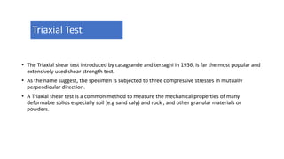
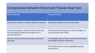
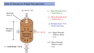
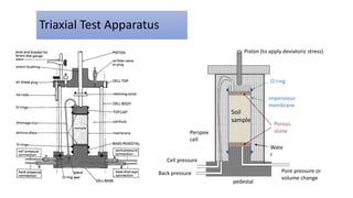
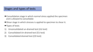
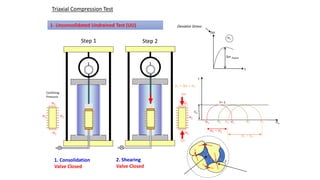
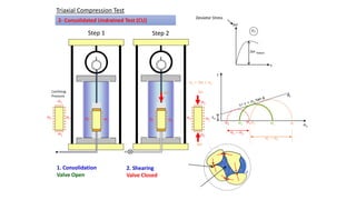
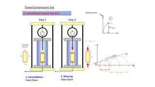
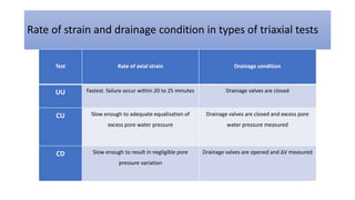
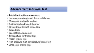
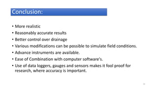
Presented To:
Honorable Teacher
Ma’am Engr. Mehwish
Presented By:
Sajid Ghafoor (2kx5-103)
Salman Hafeez (2kx5-106)
Contents:
• Shear Strength of soil
• Triaxial test of Shear Strength
SHEAR STRENGTH
The soil shear strength is a measure of its resistance to deformation
by continuous displacement of its individual soil particles.
Significance of Shear Strength
• Engineers must understand the nature of shearing resistance in order to analyze soil stability
problems such as:
• Bearing capacity
• Slope stability
• Lateral earth pressure on earth-retaining structures
• Pavement
Slope Failure in Soils
Shear Failure in Soils
Laboratory tests
• 1.Direct shear test
• 2.Triaxial shear test
A direct shear test is a laboratory or field test used by geotechnical engineers
to measures the shear strength properties of soil or rock material.
Direct Shear Test
Triaxial Test
• The Triaxial shear test introduced by casagrande and terzaghi in 1936, is far the most popular and
extensively used shear strength test.
• As the name suggest, the specimen is subjected to three compressive stresses in mutually
perpendicular direction.
• A Triaxial shear test is a common method to measure the mechanical properties of many
deformable solids especially soil (e.g sand caly) and rock , and other granular materials or
powders.
Compression between Direct and Triaxial shear test
Direct shear test Triaxial shear test
Direct shear machine is simpler and faster to operate. Progressive effective are less in the triaxial.
A tinner soil sample is used in the direct shear test,
thus facilitating drainage of pore water from a
saturated specimen.
The measurement of specimen volume changes are
more accurate in the triaxial.
Only the stresses at failure are known in the direct
shear test.
The complete state of stress is assumed to be known
at all stages during the triaxial test.
The triaxial machine is more adaptable to special
requirements.
Pore Water
Pressure u
σc
σc
q
q
σc
σc
σa = q +σc = σ1
Specimen
Length L
Specimen
Area A
ε = Axial Strain = ΔL/L
σ1 = Major Principle Stress
= Axial Stress σa
σ3 = Minor Principle Stress
= Radial Stress σr
q= Deviator stress = F/A
= Axial Load/ Area
σr = σc =σ3 σ‘1 = Major Principle
Effective Stress
= σ1-u
σ‘3= Minor Principle
Effective stress
= σ3-u 14
State of stresses on Triaxial Test specimen
Triaxial Test Apparatus
Porous
stone
impervious
membrane
Piston (to apply deviatoric stress)
O-ring
pedestal
Perspex
cell
Cell pressure
Back pressure Pore pressure or
volume change
Wate
r
Soil
sample
Procedure
• Take cylindrical soil specimen100 mm diameter and 200 mm height.
• Membrane a thin rubber layer.
• Soil prepare through mold and make required shape.
• Now specimen placed between two ridge ends in pressure chamber.
• Upper plate moves vertically and apply stress.
• Vertical stress and strain controlled through vertical axis.
• Depending on the combination of loading and drainage condition, three main
types of triaxial tests can be carried out
Stages and types of tests
Consolidation stage in which normal stress applied the specimen
and is allowed to consolidate
Shear stage in which stresses is applied to specimen to shear it.
Types of tests
1) Unconsolidated un-drained test (UU test)
2) Consolidated Un-drained test (CU test)
3) Consolidated drained test (CD test)
Triaxial Compression Test
1- Unconsolidated Undrained Test (UU)
Step 1 Step 2
sn
t
cu
t= c
s2 s1s2 s1s2 s1
s1 - s2
s1 - s2
s2 s2
s2
s2
Confining
Pressure
s1 = Ds + s2
s2
Ds
Ds
s2
s2
e
Ds
s2
Ds Failure
Deviator Stress
1. Consolidation
Valve Closed
2. Shearing
Valve Closed
Step 1 Step 2
Triaxial Compression Test
2- Consolidated Undrained Test (CU)
fu
sn
t
cu
e
Ds
s2
Ds Failure
s2
s1s2 s1
s2 s1
s1 - s2
s1 - s2
s2
s2s2 s2
s2 s2
s2 s2
s2
s2
Confining
Pressure
Ds
Ds
Ds
s1 = Ds + s2
Deviator Stress
s2
s2
1. Consolidation
Valve Open
2. Shearing
Valve Closed
Step 1 Step 2
Triaxial Compression Test
3- Consolidated Drained Test (CD)
fd
sn
t
cd
s2
s1s2 s1
s2 s1
s1 - s2
s1 - s2
s2 s2
s2
s2
Confining
Pressure
s1 = Ds + s2
s2
Ds
Ds
s2
s2
e
Ds
s2
Ds Failure
Deviator Stress
2. Shearing
Valve Open
1. Consolidation
Valve Open
Rate of strain and drainage condition in types of triaxial tests
Test Rate of axial strain Drainage condition
UU Fastest. failure occur within 20 to 25 minutes Drainage valves are closed
CU Slow enough to adequate equalisation of
excess pore water pressure
Drainage valves are closed and excess pore
water pressure measured
CD Slow enough to result in negligible pore
pressure variation
Drainage valves are opened and ΔV measured
Advancement in triaxial test
• Triaxial test options now a days
• Isotropic, anisotropic and Ko-consolidation
• Monotonic and cyclic loading
• Drained and undrained shearing
• Stress-strain-strength properties
• Creep tests
• Special testing programs
• Temperature controlled test
• Frozen triaxial test
• High pressure- high temperature triaxial test
• Large scale triaxial test.
23
Conclusion:
• More realistic
• Reasonably accurate results
• Better control over drainage
• Various modifications can be possible to simulate field conditions.
• Advance instruments are available.
• Ease of Combination with computer software's.
• Use of data loggers, gauges and sensors makes it fool proof for
research, where accuracy is important.
24

Shear test

  • 2.
    Presented To: Honorable Teacher Ma’amEngr. Mehwish Presented By: Sajid Ghafoor (2kx5-103) Salman Hafeez (2kx5-106)
  • 3.
    Contents: • Shear Strengthof soil • Triaxial test of Shear Strength
  • 4.
    SHEAR STRENGTH The soilshear strength is a measure of its resistance to deformation by continuous displacement of its individual soil particles.
  • 5.
    Significance of ShearStrength • Engineers must understand the nature of shearing resistance in order to analyze soil stability problems such as: • Bearing capacity • Slope stability • Lateral earth pressure on earth-retaining structures • Pavement
  • 6.
  • 7.
  • 10.
    Laboratory tests • 1.Directshear test • 2.Triaxial shear test
  • 11.
    A direct sheartest is a laboratory or field test used by geotechnical engineers to measures the shear strength properties of soil or rock material. Direct Shear Test
  • 12.
    Triaxial Test • TheTriaxial shear test introduced by casagrande and terzaghi in 1936, is far the most popular and extensively used shear strength test. • As the name suggest, the specimen is subjected to three compressive stresses in mutually perpendicular direction. • A Triaxial shear test is a common method to measure the mechanical properties of many deformable solids especially soil (e.g sand caly) and rock , and other granular materials or powders.
  • 13.
    Compression between Directand Triaxial shear test Direct shear test Triaxial shear test Direct shear machine is simpler and faster to operate. Progressive effective are less in the triaxial. A tinner soil sample is used in the direct shear test, thus facilitating drainage of pore water from a saturated specimen. The measurement of specimen volume changes are more accurate in the triaxial. Only the stresses at failure are known in the direct shear test. The complete state of stress is assumed to be known at all stages during the triaxial test. The triaxial machine is more adaptable to special requirements.
  • 14.
    Pore Water Pressure u σc σc q q σc σc σa= q +σc = σ1 Specimen Length L Specimen Area A ε = Axial Strain = ΔL/L σ1 = Major Principle Stress = Axial Stress σa σ3 = Minor Principle Stress = Radial Stress σr q= Deviator stress = F/A = Axial Load/ Area σr = σc =σ3 σ‘1 = Major Principle Effective Stress = σ1-u σ‘3= Minor Principle Effective stress = σ3-u 14 State of stresses on Triaxial Test specimen
  • 15.
    Triaxial Test Apparatus Porous stone impervious membrane Piston(to apply deviatoric stress) O-ring pedestal Perspex cell Cell pressure Back pressure Pore pressure or volume change Wate r Soil sample
  • 16.
    Procedure • Take cylindricalsoil specimen100 mm diameter and 200 mm height. • Membrane a thin rubber layer. • Soil prepare through mold and make required shape. • Now specimen placed between two ridge ends in pressure chamber. • Upper plate moves vertically and apply stress. • Vertical stress and strain controlled through vertical axis. • Depending on the combination of loading and drainage condition, three main types of triaxial tests can be carried out
  • 18.
    Stages and typesof tests Consolidation stage in which normal stress applied the specimen and is allowed to consolidate Shear stage in which stresses is applied to specimen to shear it. Types of tests 1) Unconsolidated un-drained test (UU test) 2) Consolidated Un-drained test (CU test) 3) Consolidated drained test (CD test)
  • 19.
    Triaxial Compression Test 1-Unconsolidated Undrained Test (UU) Step 1 Step 2 sn t cu t= c s2 s1s2 s1s2 s1 s1 - s2 s1 - s2 s2 s2 s2 s2 Confining Pressure s1 = Ds + s2 s2 Ds Ds s2 s2 e Ds s2 Ds Failure Deviator Stress 1. Consolidation Valve Closed 2. Shearing Valve Closed
  • 20.
    Step 1 Step2 Triaxial Compression Test 2- Consolidated Undrained Test (CU) fu sn t cu e Ds s2 Ds Failure s2 s1s2 s1 s2 s1 s1 - s2 s1 - s2 s2 s2s2 s2 s2 s2 s2 s2 s2 s2 Confining Pressure Ds Ds Ds s1 = Ds + s2 Deviator Stress s2 s2 1. Consolidation Valve Open 2. Shearing Valve Closed
  • 21.
    Step 1 Step2 Triaxial Compression Test 3- Consolidated Drained Test (CD) fd sn t cd s2 s1s2 s1 s2 s1 s1 - s2 s1 - s2 s2 s2 s2 s2 Confining Pressure s1 = Ds + s2 s2 Ds Ds s2 s2 e Ds s2 Ds Failure Deviator Stress 2. Shearing Valve Open 1. Consolidation Valve Open
  • 22.
    Rate of strainand drainage condition in types of triaxial tests Test Rate of axial strain Drainage condition UU Fastest. failure occur within 20 to 25 minutes Drainage valves are closed CU Slow enough to adequate equalisation of excess pore water pressure Drainage valves are closed and excess pore water pressure measured CD Slow enough to result in negligible pore pressure variation Drainage valves are opened and ΔV measured
  • 23.
    Advancement in triaxialtest • Triaxial test options now a days • Isotropic, anisotropic and Ko-consolidation • Monotonic and cyclic loading • Drained and undrained shearing • Stress-strain-strength properties • Creep tests • Special testing programs • Temperature controlled test • Frozen triaxial test • High pressure- high temperature triaxial test • Large scale triaxial test. 23
  • 24.
    Conclusion: • More realistic •Reasonably accurate results • Better control over drainage • Various modifications can be possible to simulate field conditions. • Advance instruments are available. • Ease of Combination with computer software's. • Use of data loggers, gauges and sensors makes it fool proof for research, where accuracy is important. 24