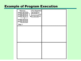
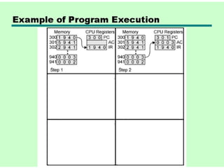
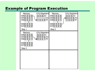
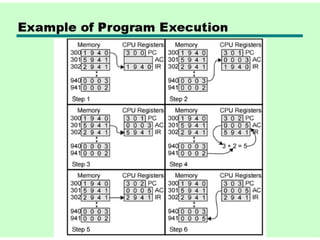
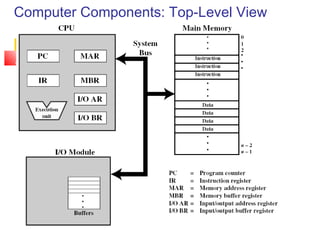
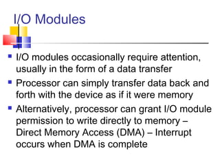
1
Chap-3
A Top Level View of Computer
Function & Interconnection
Ch-3
 Topic: Single Processor Architecture
 Reading: Stallings, Sections 3.1
through 3.3

COA
Today’s Agenda
 Computer Components
 Computer Function
 Interrupts – Types & Instruction Cycle
 Multiple Interrupts
 I/O Functions
 Interconnection Structures
Review of Three Key Concepts of von
Neumann Architecture
 Data and instructions in single read-write
memory
 Memory contents are addressable by location
regardless of whether content is data or
instruction
 Execution of code is sequential from one
instruction to the next unless a jump is
encountered
Hardwired Program
 There is a small set of basic logic components that can be
combined in various ways to store binary data and to perform
arithmetic and logical operations on that data.
 If there is a particular computation to be performed, a
configuration of logic components designed specifically for that
computation could be constructed.
 We can think of the process of connecting the various
components in the desired configuration as a form of
programming. The resulting “program” is in the form of
hardware and is termed a
hardwired program.
Hardwired Program
 Customized H/W – the system accepts data &
produces results.
Program Concept
 Just about any function can be realized with
hardwired logic components (calculator)
 Hardwired systems, however, are inflexible
 General purpose hardware can do different
tasks, given correct control signals
 Instead of re-wiring, supply a new set of control
signals
Instruction Interpreter
Now we need a device to accept unique instruction
codes and turn them into control signals for the
arithmetic and logic hardware.
How Can We Create a Program?
 Each step activates a set of control signals to
control general purpose logic
 Each step is an arithmetic or logical operation
 For each operation, a different set of control
signals is needed
 Program equals the sequence of steps
 Programming is no longer a case of rewiring
How Can We Create a Program?
 Programming is now much easier. Instead of
rewiring the hardware for each new program, all we
need to do is provide a new sequence of codes.
 Each code is, in effect, an instruction, and part of
the hardware interprets each instruction and
generates control signals.
 To distinguish this new method of programming, a
sequence of codes or instructions is called
software.
Encoding Instructions
 Unique binary patterns identify operation to
be performed.
 Examples:
 Simple addition machine in Figure 3.5 on page 89
of textbook
 A useful link for Assembly language help

http://www.plantation-productions.com/Webster/
 This URL may be used in coming classes.
Computer Components: Top-Level View
Computer Components: Detail
 The CPU exchanges data with memory. For this purpose, it
typically
makes use of two internal (to the CPU) registers:
 (1). a memory address register (MAR), which specifies the
address in memory for the next read or write,
 (2). a memory buffer register (MBR), which contains the data
to be written into memory or receives the data read from
memory.
 Similarly, an I/O address register (I/O AR) specifies a
particular I/O device.
 An I/O buffer (I/O BR) register is used for the exchange of
data between an I/O module and the CPU.
Simplified 2-Step Instruction
Cycle
 Instruction cycle is not the same thing as a
clock cycle
 Two steps:
 Fetch
 Execute
Fetch Cycle
 Program Counter (PC) holds address of next
instruction to fetch
 Processor fetches instruction from memory location
pointed to by PC
 Increment PC unless instructed otherwise
 Instruction loaded into Instruction Register (IR)
 Processor interprets instruction and performs
required actions
 What problems can you predict happening in this
cycle?
Execute Cycle
 Processor-memory
 data transfer between CPU and main memory
 Processor-I/O
 Data transfer between CPU and I/O module
 Data processing
 Some arithmetic or logical operation on data
Execute Cycle
 Control
 Alteration of sequence of operations, e.g. jump
 e.g. the processor may fetch an instruction from location
149, which specifies that the next instruction be from
location 182. The processor will remember this fact by
setting the program counter to 182.Thus, on the next fetch
cycle, the instruction will be fetched from location 182
rather than 150.
 Combination of above
Instruction Cycle State Diagram
Instruction Cycle State Diagram - Explanation
 Instruction address calculation (iac): Determine the
address of the next instruction to be executed. Usually, this
involves adding a fixed number to the address of the
previous instruction.
 Instruction fetch (if): Read instruction from its memory
location into the processor.
 Instruction operation decoding (iod): Analyze
instruction to determine type of operation to be performed
and operand(s) to be used.
 Operand address calculation (oac): If the operation
involves reference to an operand in memory or available via
I/O, then determine the address of the operand.
Instruction Cycle State Diagram - Explanation
 Operand fetch (of): Fetch the operand from
memory or read it in from I/O.
 Data operation (do): Perform the operation
indicated in the instruction.
 Operand store (os): Write the result into
memory or out to I/O.
Interrupts
 No special code is needed in main code
 Interrupt Service Routines (ISR) handle
condition
 Interrupts may be disabled; pending interrupts
serviced as soon as interrupts are enabled
again
 Global enabling – affects all maskable
interrupts
 Local enabling – affects individual interrupts
Types of Interrupts
 Program – Something that occurs as a result of program
execution such as illegal instructions, arithmetic overflow,
divide by zero, or memory handling error
 Timer – Generated by one of the processor's internal
timers so that the processor can perform some time-
scheduled task
 I/O – Generated by an I/O controller to request service
from the processor such as keyboard, mouse, NIC, disk
drive
 Hardware failure – signifies some error condition with the
hardware
Multiple Interrupts
 Disable interrupts
 Processor can ignore further interrupts whilst
processing one interrupt or interrupts may be nested
 Ignored interrupts remain pending and are checked
after first interrupt has been processed
 Define priorities
 Low priority interrupts can be interrupted by higher
priority interrupts
 When higher priority interrupt has been processed,
processor returns to previous interrupt
CPU Context Switch From Process to Process
Program Flow Control
Interrupt Cycle
Interrupt Cycle (continued)
 Added to instruction cycle
 Processor checks for interrupt
 If no interrupt, fetch next instruction
 If interrupt pending:
 Suspend execution of current program
 Save context on stack (typically registers, PC, flags, etc.)
 Set PC to start address of interrupt handler routine
 Process interrupt
 Restore context and continue interrupted program
Transfer of Control via Interrupts
Program Timing -- Short I/O Wait
Program Timing -- Long I/O Wait
Instruction Cycle (with
Interrupts) - State Diagram
Multiple Interrupts - Sequential
Multiple Interrupts – Nested
Time Sequence of Multiple Interrupts
I/O Modules
 I/O modules occasionally require attention,
usually in the form of a data transfer
 Processor can simply transfer data back and
forth with the device as if it were memory
 Alternatively, processor can grant I/O module
permission to write directly to memory –
Direct Memory Access (DMA) – Interrupt
occurs when DMA is complete

03. top level view of computer function & interconnection

  • 1.
    1 Chap-3 A Top LevelView of Computer Function & Interconnection Ch-3  Topic: Single Processor Architecture  Reading: Stallings, Sections 3.1 through 3.3  COA
  • 2.
    Today’s Agenda  ComputerComponents  Computer Function  Interrupts – Types & Instruction Cycle  Multiple Interrupts  I/O Functions  Interconnection Structures
  • 3.
    Review of ThreeKey Concepts of von Neumann Architecture  Data and instructions in single read-write memory  Memory contents are addressable by location regardless of whether content is data or instruction  Execution of code is sequential from one instruction to the next unless a jump is encountered
  • 4.
    Hardwired Program  Thereis a small set of basic logic components that can be combined in various ways to store binary data and to perform arithmetic and logical operations on that data.  If there is a particular computation to be performed, a configuration of logic components designed specifically for that computation could be constructed.  We can think of the process of connecting the various components in the desired configuration as a form of programming. The resulting “program” is in the form of hardware and is termed a hardwired program.
  • 5.
    Hardwired Program  CustomizedH/W – the system accepts data & produces results.
  • 6.
    Program Concept  Justabout any function can be realized with hardwired logic components (calculator)  Hardwired systems, however, are inflexible  General purpose hardware can do different tasks, given correct control signals  Instead of re-wiring, supply a new set of control signals
  • 7.
    Instruction Interpreter Now weneed a device to accept unique instruction codes and turn them into control signals for the arithmetic and logic hardware.
  • 8.
    How Can WeCreate a Program?  Each step activates a set of control signals to control general purpose logic  Each step is an arithmetic or logical operation  For each operation, a different set of control signals is needed  Program equals the sequence of steps  Programming is no longer a case of rewiring
  • 9.
    How Can WeCreate a Program?  Programming is now much easier. Instead of rewiring the hardware for each new program, all we need to do is provide a new sequence of codes.  Each code is, in effect, an instruction, and part of the hardware interprets each instruction and generates control signals.  To distinguish this new method of programming, a sequence of codes or instructions is called software.
  • 10.
    Encoding Instructions  Uniquebinary patterns identify operation to be performed.  Examples:  Simple addition machine in Figure 3.5 on page 89 of textbook  A useful link for Assembly language help  http://www.plantation-productions.com/Webster/  This URL may be used in coming classes.
  • 17.
  • 18.
    Computer Components: Detail The CPU exchanges data with memory. For this purpose, it typically makes use of two internal (to the CPU) registers:  (1). a memory address register (MAR), which specifies the address in memory for the next read or write,  (2). a memory buffer register (MBR), which contains the data to be written into memory or receives the data read from memory.  Similarly, an I/O address register (I/O AR) specifies a particular I/O device.  An I/O buffer (I/O BR) register is used for the exchange of data between an I/O module and the CPU.
  • 19.
    Simplified 2-Step Instruction Cycle Instruction cycle is not the same thing as a clock cycle  Two steps:  Fetch  Execute
  • 20.
    Fetch Cycle  ProgramCounter (PC) holds address of next instruction to fetch  Processor fetches instruction from memory location pointed to by PC  Increment PC unless instructed otherwise  Instruction loaded into Instruction Register (IR)  Processor interprets instruction and performs required actions  What problems can you predict happening in this cycle?
  • 21.
    Execute Cycle  Processor-memory data transfer between CPU and main memory  Processor-I/O  Data transfer between CPU and I/O module  Data processing  Some arithmetic or logical operation on data
  • 22.
    Execute Cycle  Control Alteration of sequence of operations, e.g. jump  e.g. the processor may fetch an instruction from location 149, which specifies that the next instruction be from location 182. The processor will remember this fact by setting the program counter to 182.Thus, on the next fetch cycle, the instruction will be fetched from location 182 rather than 150.  Combination of above
  • 23.
  • 24.
    Instruction Cycle StateDiagram - Explanation  Instruction address calculation (iac): Determine the address of the next instruction to be executed. Usually, this involves adding a fixed number to the address of the previous instruction.  Instruction fetch (if): Read instruction from its memory location into the processor.  Instruction operation decoding (iod): Analyze instruction to determine type of operation to be performed and operand(s) to be used.  Operand address calculation (oac): If the operation involves reference to an operand in memory or available via I/O, then determine the address of the operand.
  • 25.
    Instruction Cycle StateDiagram - Explanation  Operand fetch (of): Fetch the operand from memory or read it in from I/O.  Data operation (do): Perform the operation indicated in the instruction.  Operand store (os): Write the result into memory or out to I/O.
  • 26.
    Interrupts  No specialcode is needed in main code  Interrupt Service Routines (ISR) handle condition  Interrupts may be disabled; pending interrupts serviced as soon as interrupts are enabled again  Global enabling – affects all maskable interrupts  Local enabling – affects individual interrupts
  • 27.
    Types of Interrupts Program – Something that occurs as a result of program execution such as illegal instructions, arithmetic overflow, divide by zero, or memory handling error  Timer – Generated by one of the processor's internal timers so that the processor can perform some time- scheduled task  I/O – Generated by an I/O controller to request service from the processor such as keyboard, mouse, NIC, disk drive  Hardware failure – signifies some error condition with the hardware
  • 28.
    Multiple Interrupts  Disableinterrupts  Processor can ignore further interrupts whilst processing one interrupt or interrupts may be nested  Ignored interrupts remain pending and are checked after first interrupt has been processed  Define priorities  Low priority interrupts can be interrupted by higher priority interrupts  When higher priority interrupt has been processed, processor returns to previous interrupt
  • 30.
    CPU Context SwitchFrom Process to Process
  • 31.
  • 32.
  • 33.
    Interrupt Cycle (continued) Added to instruction cycle  Processor checks for interrupt  If no interrupt, fetch next instruction  If interrupt pending:  Suspend execution of current program  Save context on stack (typically registers, PC, flags, etc.)  Set PC to start address of interrupt handler routine  Process interrupt  Restore context and continue interrupted program
  • 34.
    Transfer of Controlvia Interrupts
  • 35.
    Program Timing --Short I/O Wait
  • 36.
    Program Timing --Long I/O Wait
  • 37.
  • 38.
  • 39.
  • 40.
    Time Sequence ofMultiple Interrupts
  • 41.
    I/O Modules  I/Omodules occasionally require attention, usually in the form of a data transfer  Processor can simply transfer data back and forth with the device as if it were memory  Alternatively, processor can grant I/O module permission to write directly to memory – Direct Memory Access (DMA) – Interrupt occurs when DMA is complete