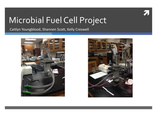
This document describes a student project to design and build a microbial fuel cell (MFC) capable of producing electricity from microorganisms. The goals were to capture electrons from microbial respiration, produce usable power, and construct a lab-scale MFC structure compatible with microbes. Materials and methods are outlined for fabricating the MFC, inoculating it, taking measurements over time, and calculating power output. Challenges encountered and potential design improvements are also discussed.
2. Recognition of Problem and Need
Globally energy use continues to increase
Most energy sources used today are non-renewable (coal, oil, natural gas)
Electricity production from non-renewable resources produces harmful by-products
Generation of electricity produces more pollution than any other single industry in the U.S.
Define the problem at hand :
Design a microbial fuel cell capable of producing recoverable electrical power
from natural microorganisms.
3. Goals of the MFC Project
Process goals:
To capture the electrons processed by microorganisms during cellular
respiration
To create a process that would produce usable electrical power
Structural goals:
Structure must be of lab scale magnitude
Materials must be biologically compatible with yeast, bacteria, and
algae
Must be 75% recycled material by weight
Mechanical Goals:
Must be capable of operating as either batch or CSTR
4. Constraints and Considerations
Constraints
Cost of materials can not exceed $10 excluding the price of the
CEM
Must be able to fabricate ourselves using the available equipment
in the fabrication shop
Other Considerations
Need to be able to safely construct the structure
Try incorporating natural materials (less man-made)
Be able to reuse the reactor
Ultimately be able to harness the energy produced to power a
device
5. Scientific Journal References
“Novel anti-flooding
poly(dimethylsiloxane) (PDMS)
catalyst for microbial fuel cells”
Adopted Ideas:
Need a good source of
oxygen for cathode (algae)
Batch Reactor
Differences:
Ours was a laboratory scale
We had a water cathode
“ Comparitive study of three
types of microbial fuel cells”
Adopted Ideas:
General original design was
a simplified version of theirs
Used same calculation for
power and optimum
resistance
Differences:
They were comparing the
efficiency of three different
types of MFC’s
6. Past Experiences and Heuristics
We incorporated a lot of
knowledge from past labs we
had done, Specifically the CSTR
lab.
Process used to measure
the volume of our anode
chamber
Similar construction of the
anode chamber
We had originally planned
to have a stir bar in the
anode chamber
8. Materials
Chose Plexiglas
Lexan was known to turn yellow over time
Wood would absorb water
Biochar as electrode – recycled component
Wire mesh was used to create the pouches to
hold biochar
Copper Wire use to connect anode and cathode
to the resistor
Foam plug and two plastic stoppers in the anode
chamber (all new)
CEM and rubber used between the two chambers
Screws, washers and wing nuts used to hold the
two chambers together
Algae in cathode
Mixed culture of heterotrophic bacteria in anode
9. Fabrication
A miter saw was used to cut the cylindrical acrylic
as well as the flat square pieces.
A hole saw was used to create the holes in the
rubber and flat acrylic in between the chambers.
Screw holes drilled with drill press
Acrylic was pieced together using a chemical
welding process
Silicon was used to reinforce inlet, outlet, and
wire ports
10. Chamber Solutions
Anode Chamber
1 gram glucose
0.25 gram organic nitrogen
source
0.02 gram K2HPO4 (P source)
50 mL viable heterotrophic
bacteria culture
1 L tap water
0.1 mL 1% Resazurin solution
Cathode Chamber
Algae media
Approximately 50 mL of algae
11. Calculation of Internal Resistance
Ohm’s Law 푉 = 퐼 × 푅
Voltage produced at various resistances was used to calculate the current by re-arranging
ohm’s law:
The current was then graphed vs. voltage to calculate the internal resistance of
our MFC
I =
푉
푅
V = -381.13 (I) + 0.0116
0.016
0.014
0.012
0.01
0.008
0.006
0.004
0.002
0
Polarization Curve
0 0.000005 0.00001 0.000015 0.00002 0.000025
Voltage (V) [V]
Current (I) [A]
Internal Resistance = 381 Ω
12. Internal Resistance after a Week
V = -760.1(I) + 0.0071
0.008
0.007
0.006
0.005
0.004
0.003
0.002
0.001
0
0.E+00 1.E-06 2.E-06 3.E-06 4.E-06 5.E-06 6.E-06 7.E-06 8.E-06 9.E-06
Voltage (V) [V]
Current (I) [A]
13. Arising Problems and Solutions
Microbes produced gas which
accumulated in top of anode chamber
Water was pumped in to force the gas
out (11/29/2012)
Unsure of the contact of the wire with
the biochar
Used plastic ties to create contact and
frayed the end of the wire
(11/27/2012)
Media in anode chamber became
contaminated with yeast
Drained and re-inoculated
(11/30/2012)
14. Calculation of Power
Ohm’s Law 푉 = 퐼 × 푅
Power is defined as
푒푛푒푟푔푦
푡푖푚푒
,
I has units of
퐽표푢푙푒푠
퐶표푢푙표푚푏
V has units of
퐶표푢푙표푚푏푠
푆푒푐표푛푑
So to get power:
푉2
푅
or
푃 =
푃 = 퐼 × 푉
Sample Calculation:
V = 0.014 V
R = 381 Ω
푃 =
0.014 푉
381 Ω
= 3.67 × 10⁻⁵ W
15. Resulting Power Density
8.E-07
7.E-07
6.E-07
5.E-07
4.E-07
3.E-07
2.E-07
1.E-07
0.E+00
0 50 100 150 200 250
Power Density (PDV) [W/L]
Time (t) [hr]
17. Conclusions
After re-inoculating our anode chamber
and fraying the end of our cathode wire,
our MFC finally began to show the results
we were hoping for.
Though the power our MFC conducts is
quite small, on a larger and more efficient
scale it might produce a usable amount of
power.
Even after data collection stopped, the
MFC is continuing to produce more power.
18. Redesign
Use stir bar in the anode chamber and
aerator in the cathode chamber for
mixing
Position reactor on its side for
convenience in pumping in material and
ensuring water contact with membrane
Use crushed graphite over biochar to
keep solution clear
Design some surface for the algae to
grow on so it does not grow over the
CEM
19. References
http://www.science.smith.edu/~jcardell/Courses/EGR325/Readings/ElecPollution_
EnvDef.pdf
BE 212 Fundamentals of BE Syllabus, Drapcho, Fall 2012
BE 212 Lab 1 Notes, Drapcho, Fall 2012
Zhang, Fang, Guang Chen, Michael A. Hickner, and Bruce E. Logan. "Novel Anti-flooding
Poly(dimethylsiloxane) (PDMS) Catalyst Binder for Microbial Fuel Cell
Cathodes." Journal of Power Sources (2012): n. pag. 4 July 2012. Web. 4 Dec. 2012.
Greenman, John, Ioannis A. Ieropoulos, John Hart, and Chris Melhuish.
"Comparitive Study of Three Types of Microbial Fuel Cell." Enzyme and Microbial
Technology 37.2 (2005): 238-45. 20 Apr. 2005. Web. 4 Dec. 2012.
<http://dx.doi.org/10.1016/j.enzmictec.2005.03.006>.
BE 212 Lab 3 Notes, Drapcho, Fall 2012
20. Appendices
Table 1. Values from testing MFC with media at beginning of week
Resistance (R) [Ω] Current (I) [A] Voltage (V) [V] Power (P) [W] Power Density (PDV) [W/L]
20 0.000E+00 0 0.000E+00 0.000E+00
66 1.515E-05 0.001 1.515E-08 1.515E-11
206 1.942E-05 0.004 7.767E-08 3.107E-10
501 1.796E-05 0.009 1.617E-07 1.455E-09
2461 2.844E-06 0.007 1.991E-08 1.394E-10
5030 2.982E-06 0.015 4.473E-08 6.710E-10
22. Appendices
Table 3. Values used in calculating the polarization curve at end of week
Resistance (R) [Ω] Voltage (V) [V] Current (I) [A]
260 0.002 7.69231E-06
554 0.002 3.61011E-06
2486 0.006 2.41352E-06
4900 0.007 1.42857E-06
Editor's Notes
Kelly
Engineering design process
Kelly
Shannen
Caitlyn
I will talk about this one a lot
For the first source I will say that their design was very different than ours in that it was actually in the soil and on a much larger scale and had an air cathode but from it we adopted two ideas which were to have ours work as a batch reactor and that we needed to have a really good source of oxygen in our cathode because they struggled with that. We also wanted to use a natural source of oxygen for our cathode and that is why we chose to use algae instead of a mechanical aerator
The one one the right is pretty straight forward
Discuss similarities and differences between our anode chamber and the picture of the CSTR from the lab
Caitlyn
Shannen
Just talk about the changes we made from the original design to the final design
Shannen
Talk about materials here
Be sure to mention was was used and what was new and what was natural blah blah blah
Kelly
Kelly
Mix algae pic
Caitlyn
B/c V/I = R
Caitlyn
Shannen
Kelly
I was calculated from V and R. I was then multiplied by I to get power. ADD SAMPLE WITH NUMBERS
Kelly
Re-inoculated at 120 hrs.
Caitlyn
Caitlyn
Shannen
I think we need like an MLA format for the first reference
Because we had so many data points I only showed the points after we had re-inoculated, Also, I am not sure if we are supposed to put this here or as another part of the appendices.