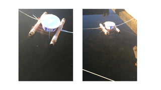
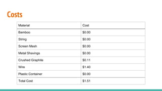
The document discusses the development of a microbial fuel cell (MFC) aimed at achieving a power density of 1 watt per cubic meter of anode volume using primarily natural materials. It outlines the design methodology, experiments conducted, results, and evaluations of its performance, highlighting the use of various materials like bamboo and aluminum to enhance efficiency. The study concludes with a maximum achieved power density of 0.1298 W/m³ and suggestions for further research to improve performance.


![Resistance
(R) [ohms]
Voltage (V)
[V]
Current (I)
[A]
189 0.04 0.000212
516 0.07 0.000136
1000 0.08 0.00008
1468 0.084 5.72E-05
2238 0.083 3.71E-05
2984 0.08 2.68E-05
5250 0.1 1.9E-05
4450 0.095 2.13E-05](https://image.slidesharecdn.com/calfehundknightrichardson-171212004038/85/Microbial-Fuel-Cell-Project-29-320.jpg)

![Voltage (V)
[V]
Resistance (R)
[ohms]
Current (I) [A]
0.098 254.8 0.000384615
0.181 852 0.000212441
0.202 1345 0.000150186
0.207 2233 9.27004E-05
0.249 3452 7.21321E-05
0.239 4310 5.54524E-05
0.244 5230 4.66539E-05
0.059 152.2 0.000387648](https://image.slidesharecdn.com/calfehundknightrichardson-171212004038/85/Microbial-Fuel-Cell-Project-32-320.jpg)


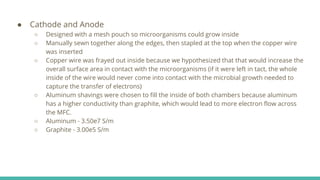
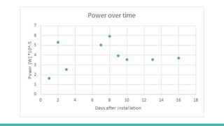
![MFC Raw Data sheet Anode Volume (V) [m3
] Internal Resistance (R) [Ω]
0.0004572 259
Date Volts (V) [V] Temp (ºC) Current (I) [A] Power (P) [W] Power Density (PDV
) [W/m3
]
11/4/2015 0.065 18.4 0.00025097 1.63E-05 0.0357
11/5/2015 0.117 18.7 0.00045174 5.29E-05 0.1156
11/6/2015 0.081 22.0 0.00031274 2.53E-05 0.0554
11/10/2015 0.114 17.7 0.00044015 5.02E-05 0.1097
11/11/2015 0.124 19.1 0.00047876 5.94E-05 0.1298
11/12/2015 0.101 16.3 0.00038996 3.94E-05 0.0861
11/13/2015 0.096 16.5 0.00037066 3.56E-05 0.0778
11/16/2015 0.096 13.5 0.00037066 3.56E-05 0.0778
11/19/2015 0.098 18.6 0.00037838 3.71E-05 0.0811](https://image.slidesharecdn.com/calfehundknightrichardson-171212004038/85/Microbial-Fuel-Cell-Project-37-320.jpg)


