Downloaded 111 times
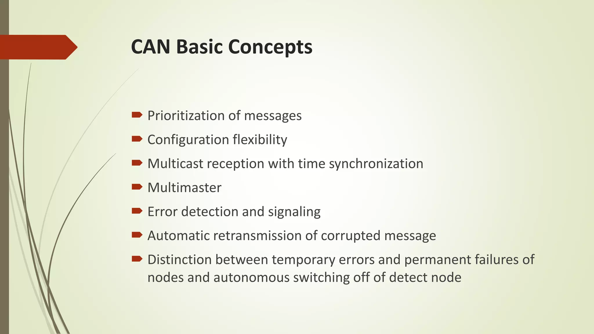
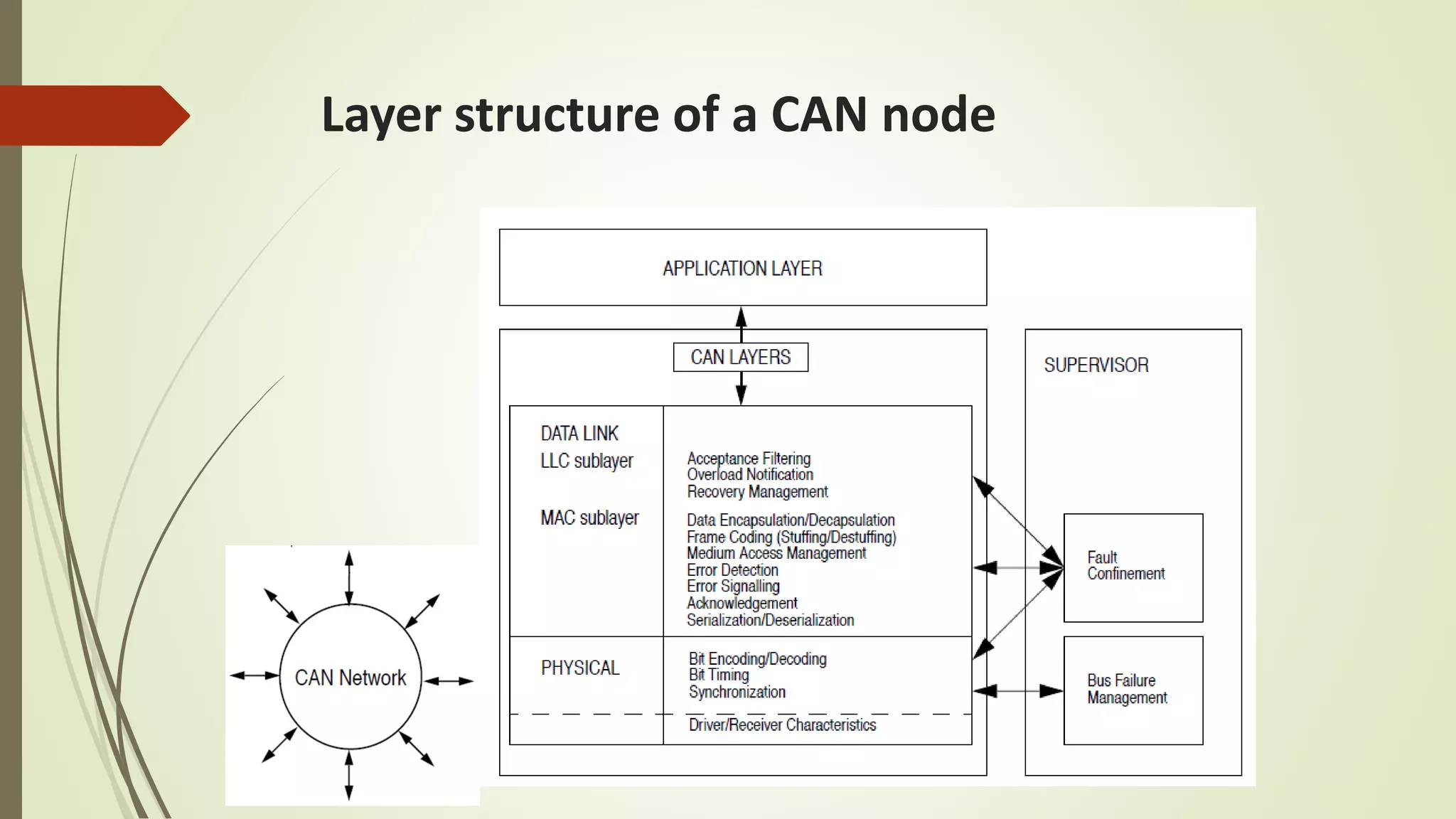
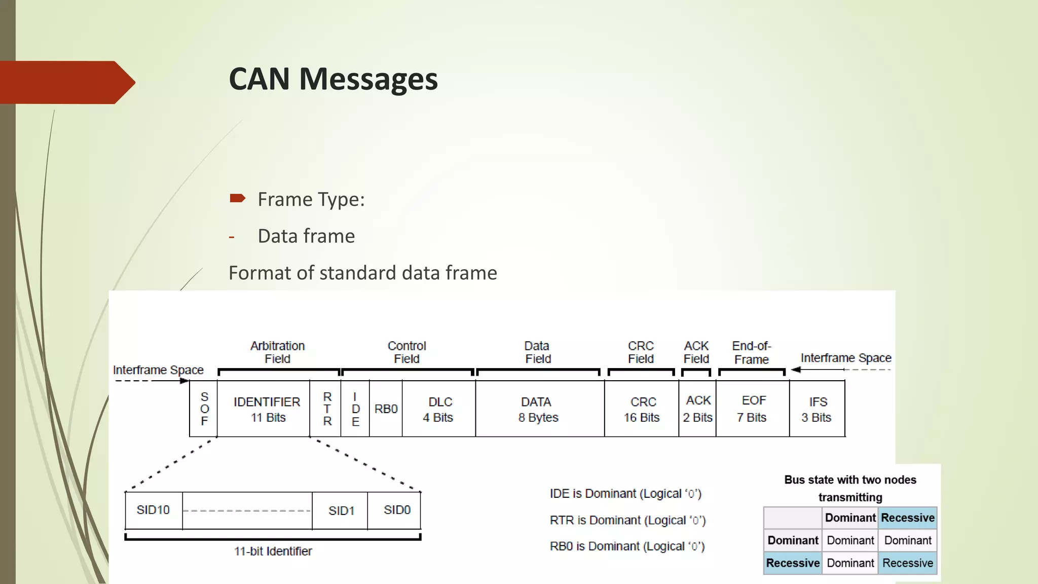
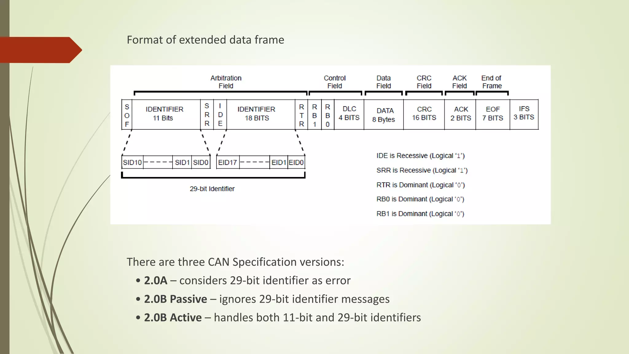
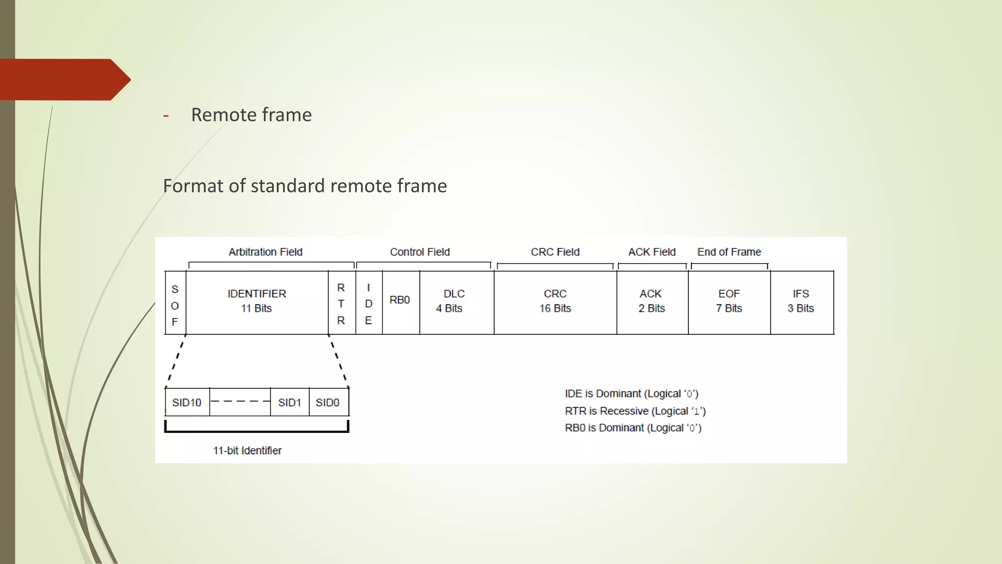
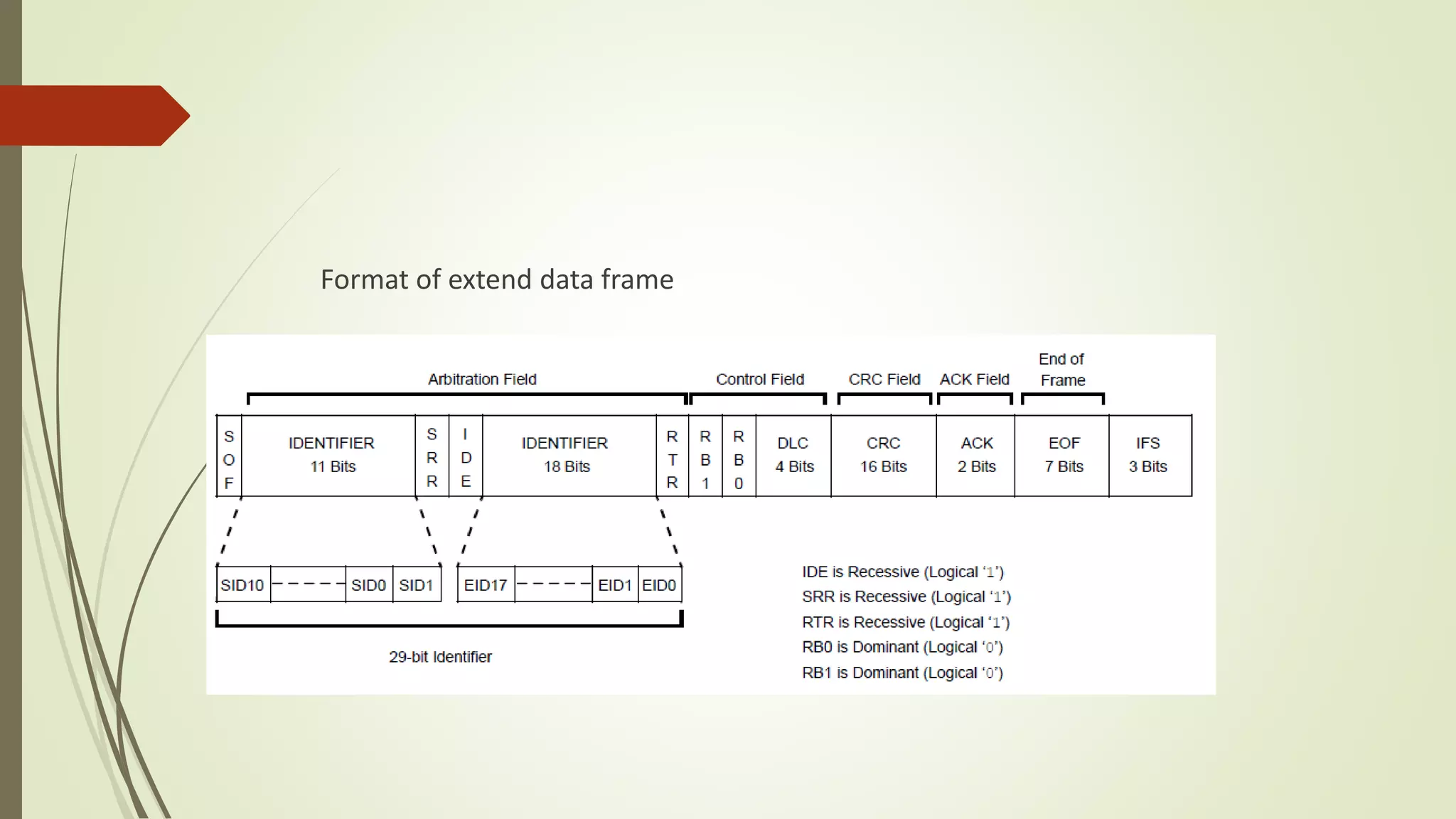
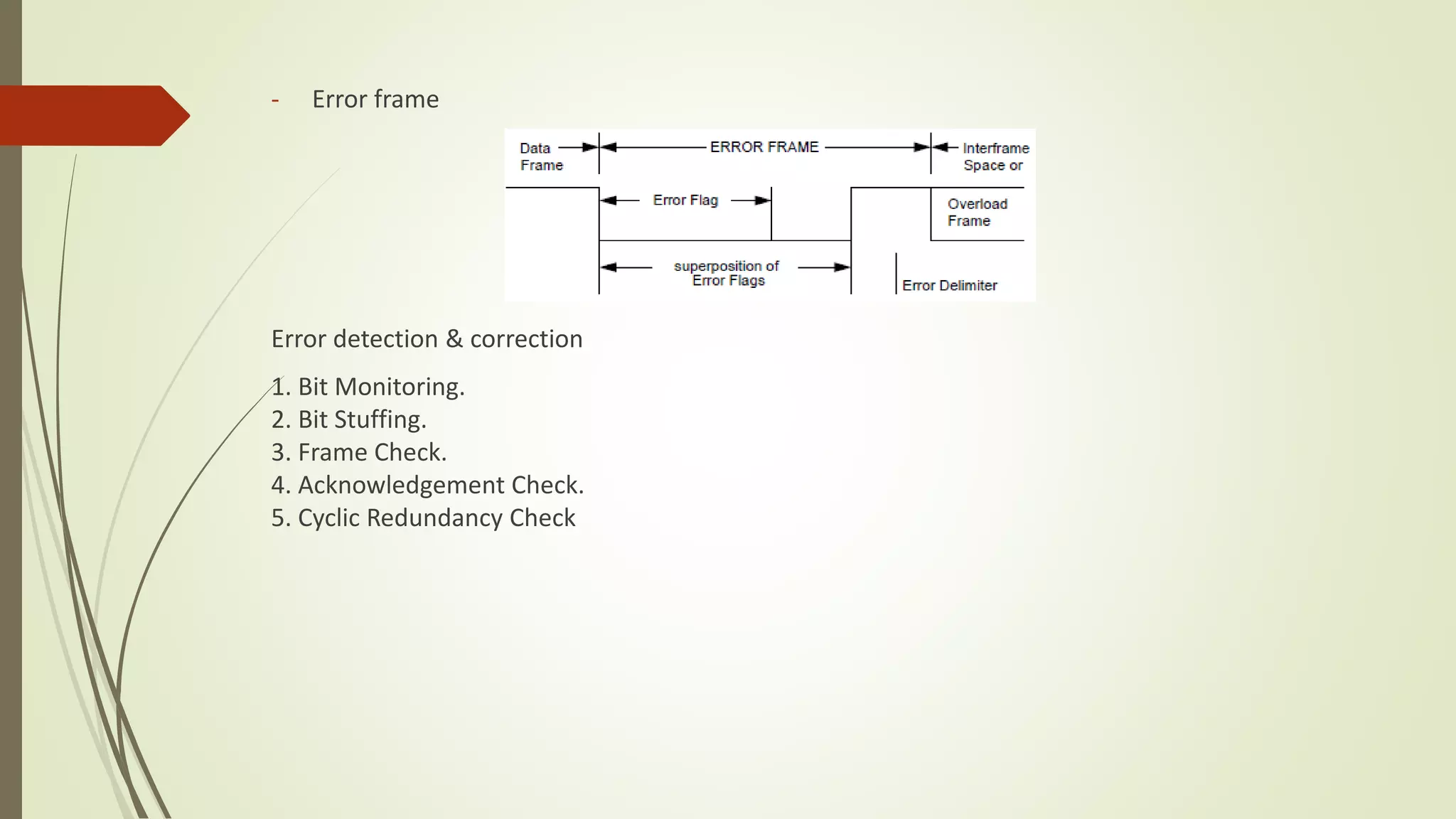
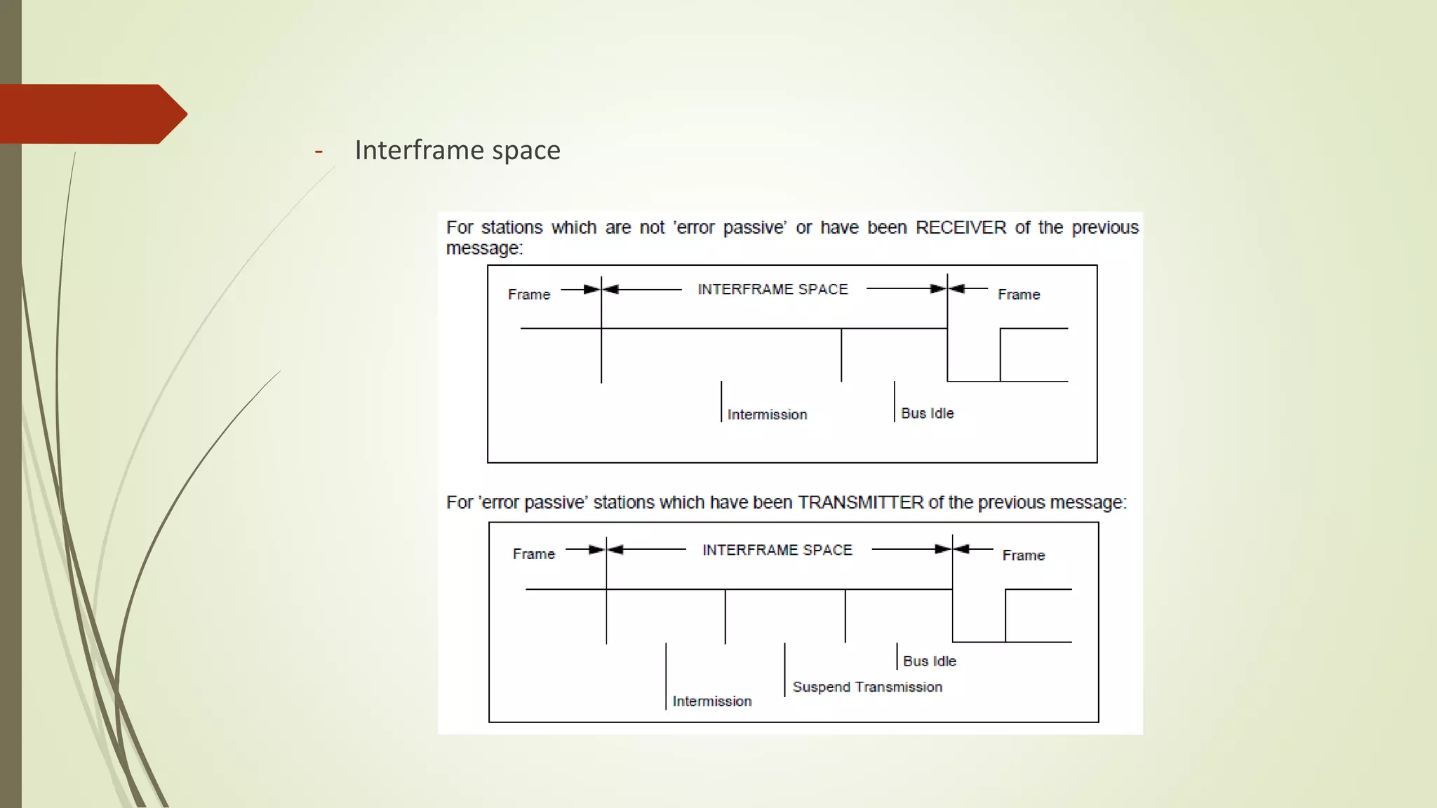
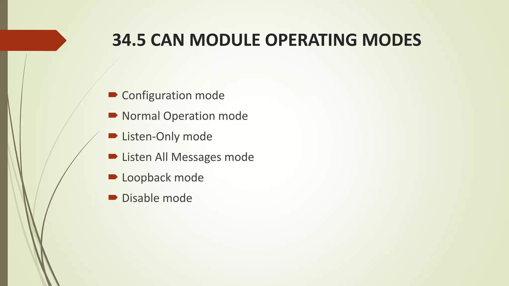

The document provides an overview of Controller Area Network (CAN) computer networks, detailing key concepts such as message prioritization, configuration flexibility, and error detection mechanisms. It describes CAN node structures and various frame types, including standard and extended data frames, along with specifications from three versions: 2.0a, 2.0b passive, and 2.0b active. Additionally, it outlines different operating modes for CAN modules, including normal and listen-only modes.


