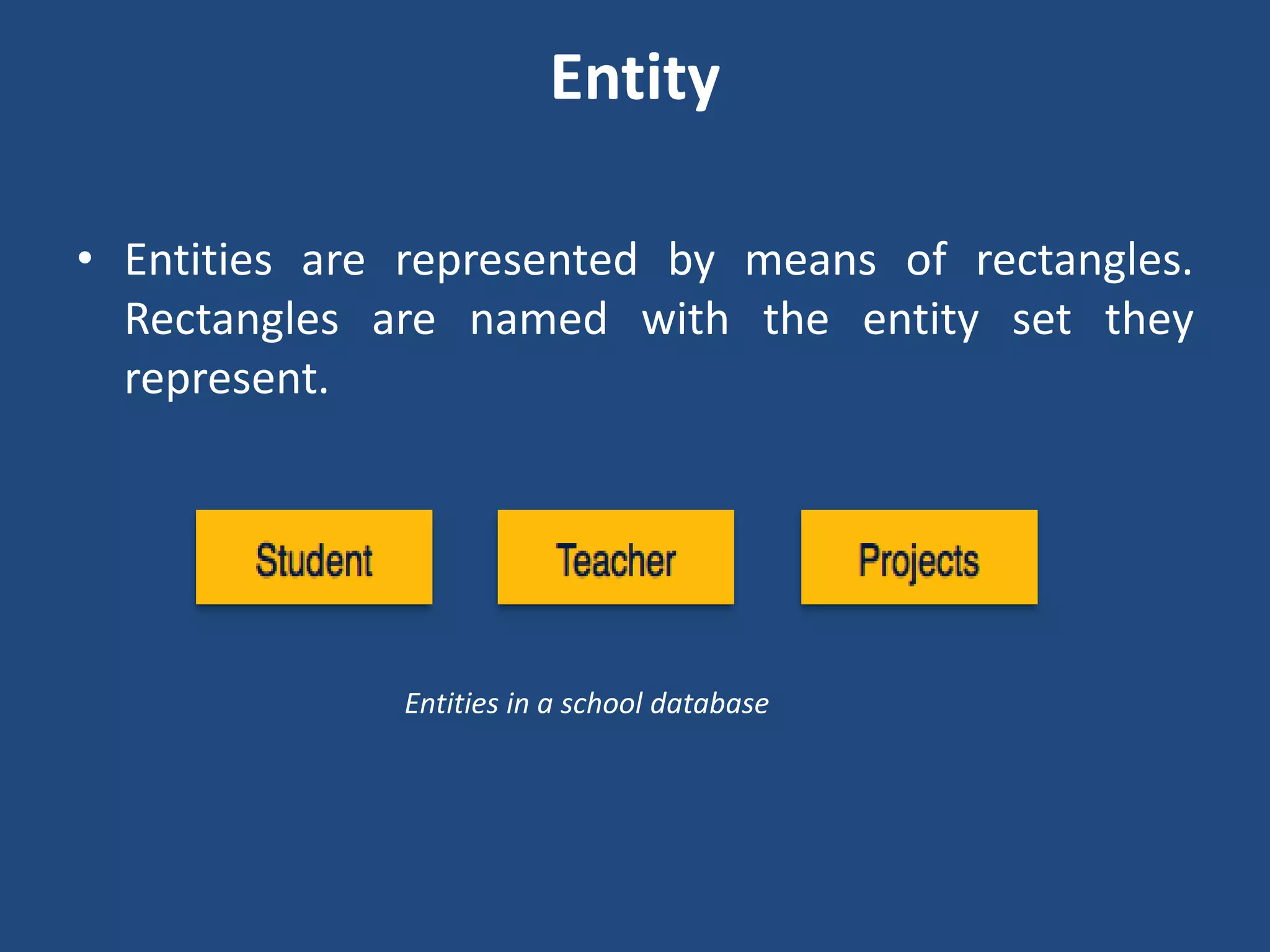
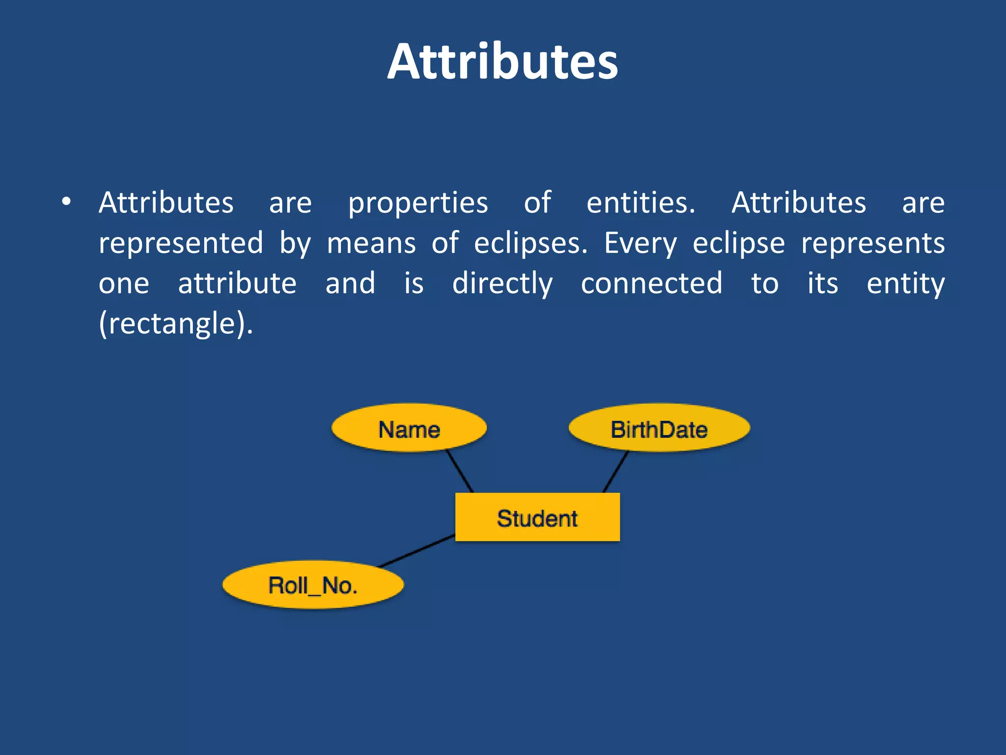
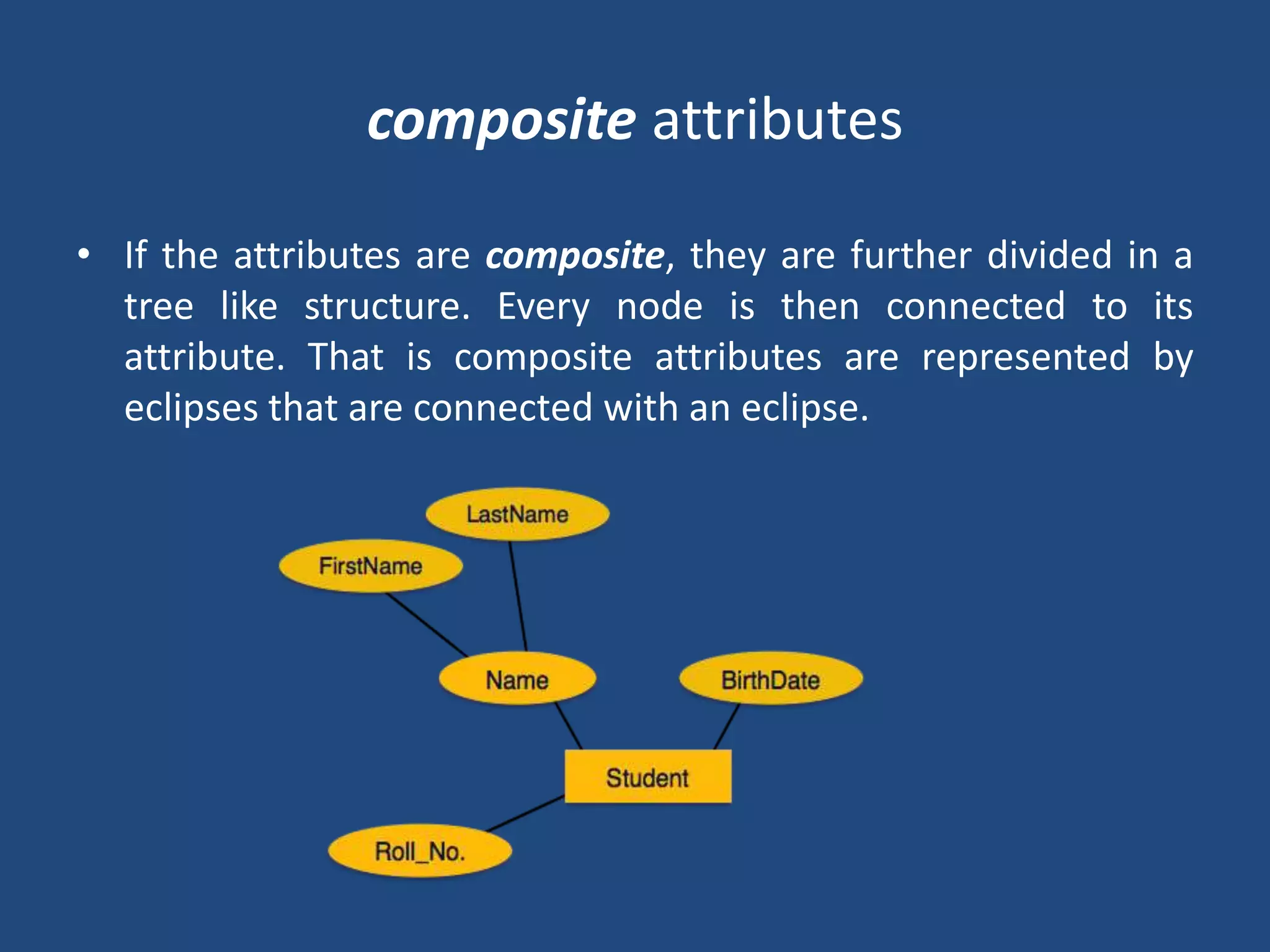
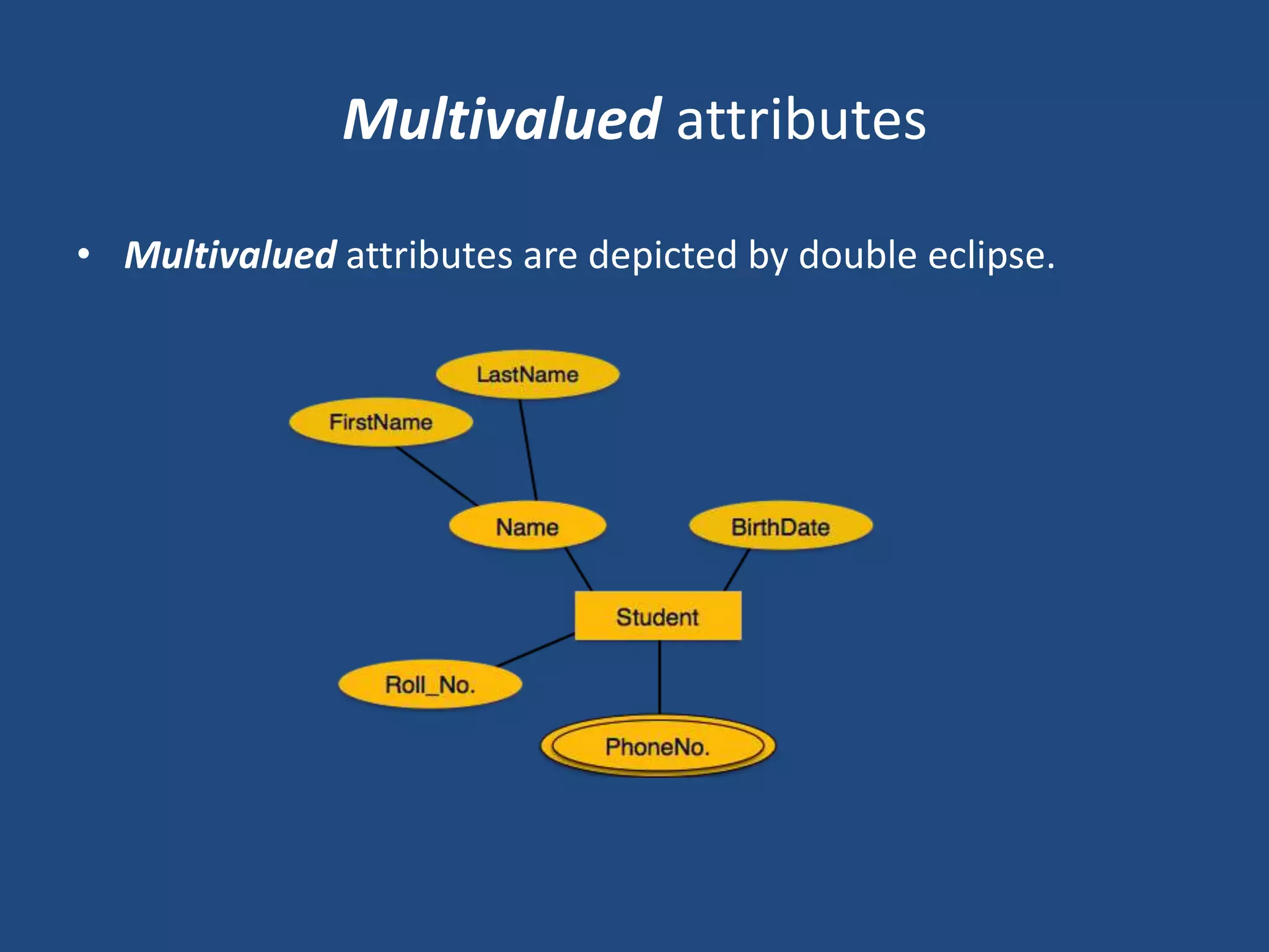
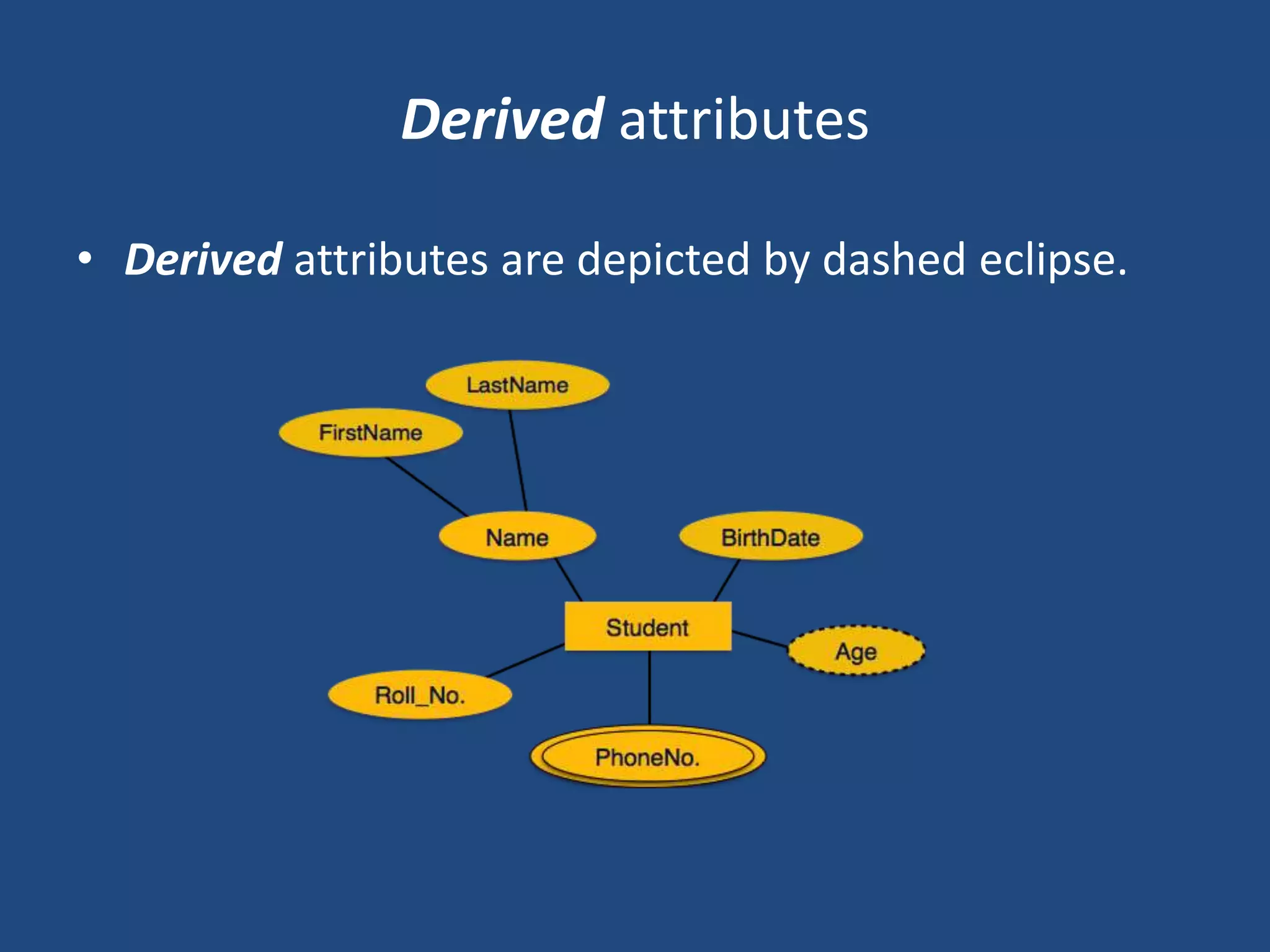
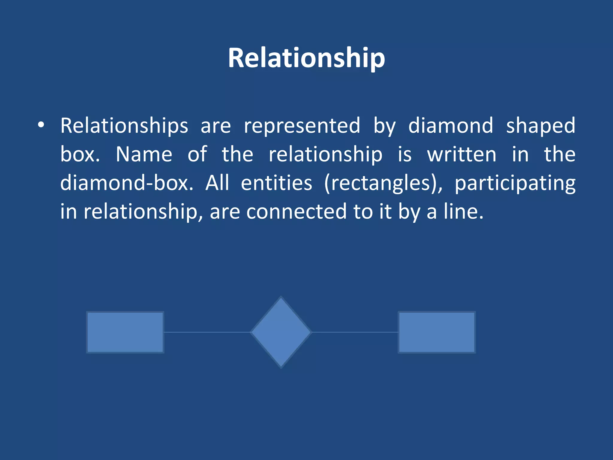
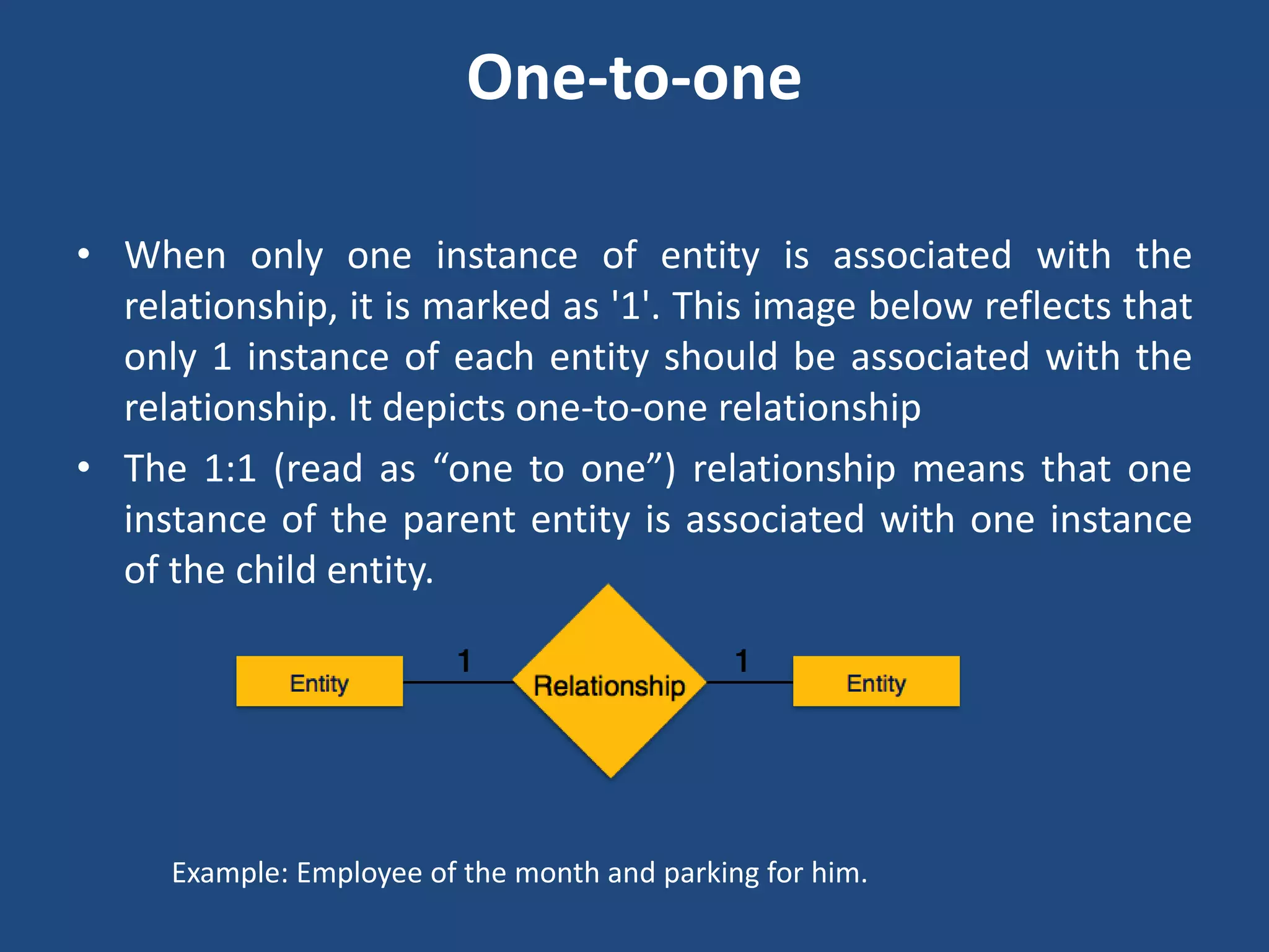
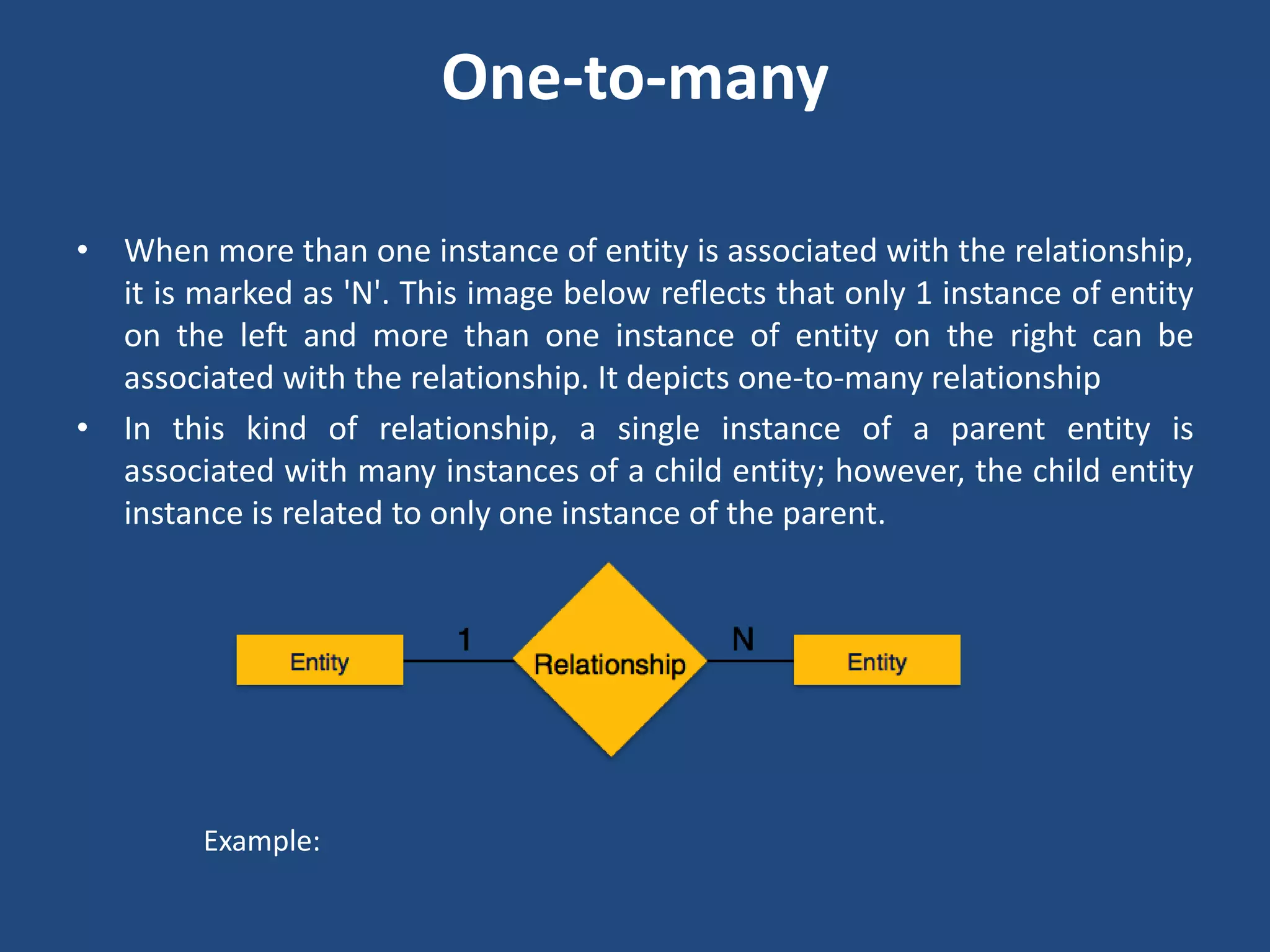
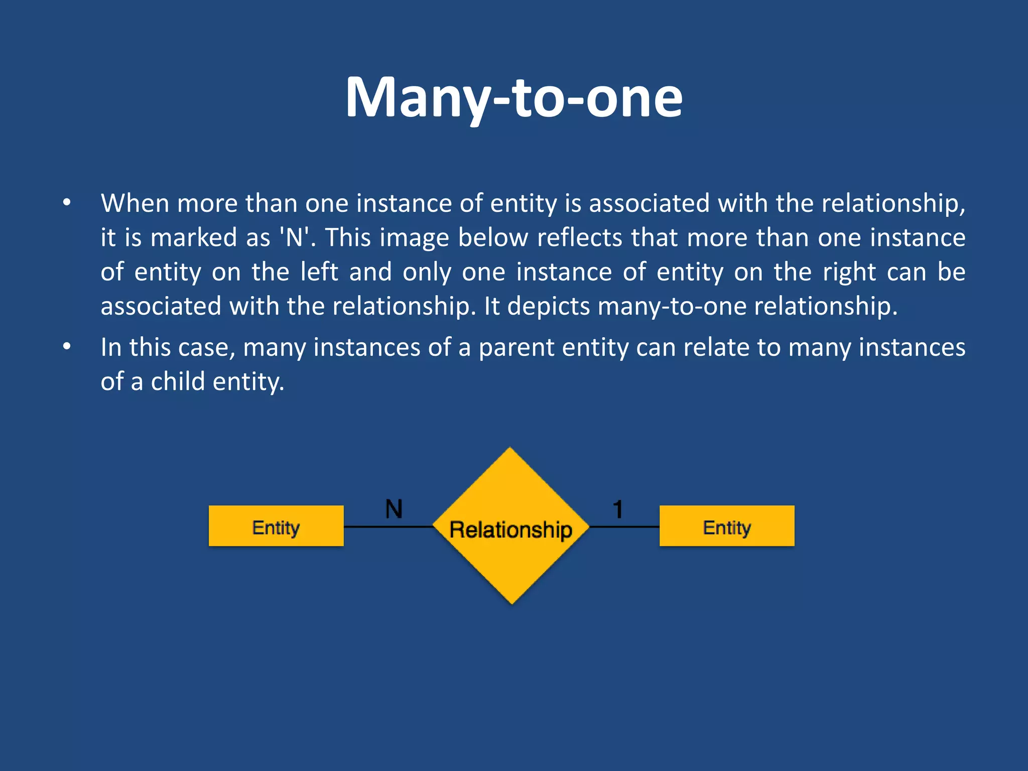
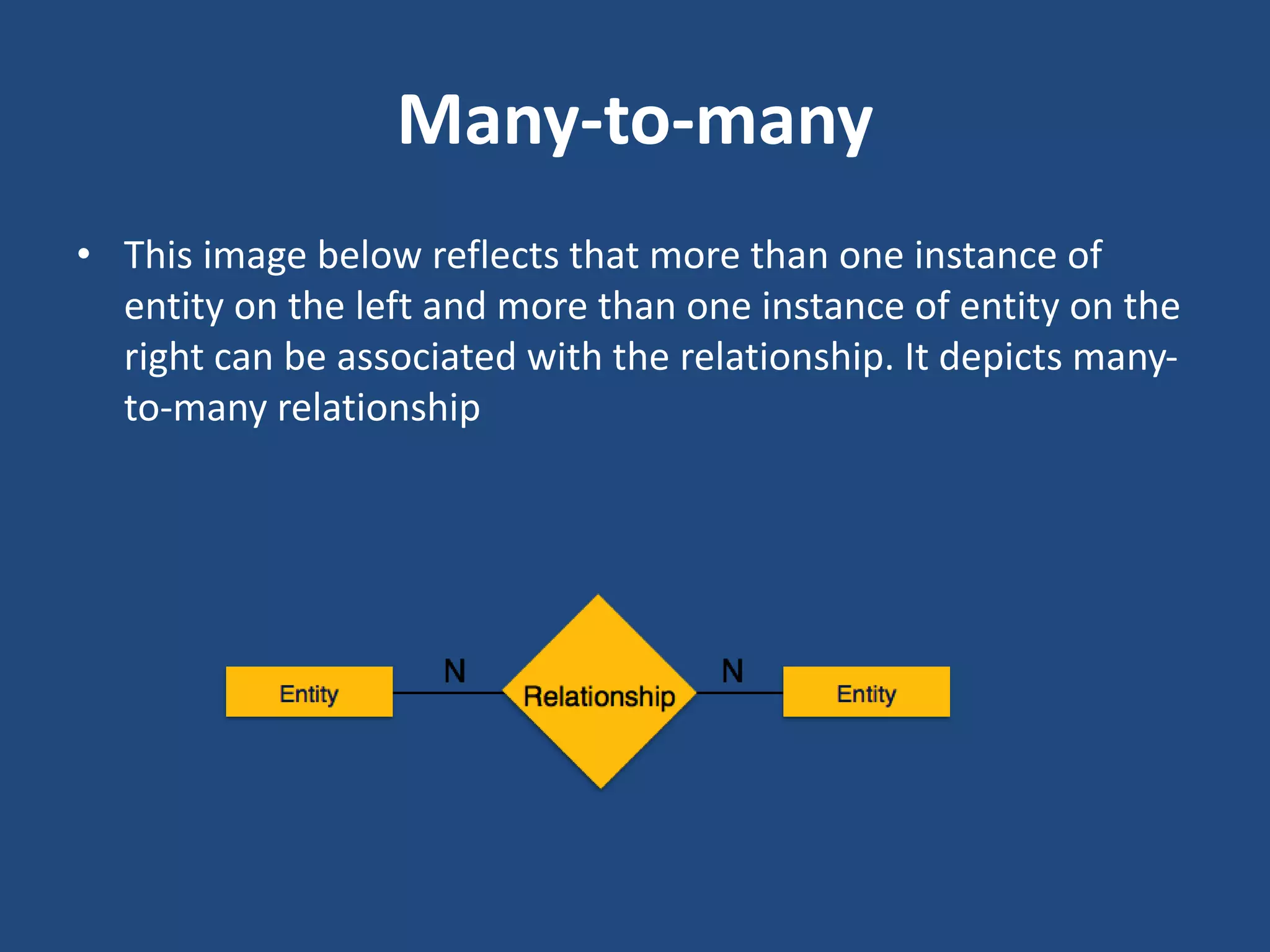
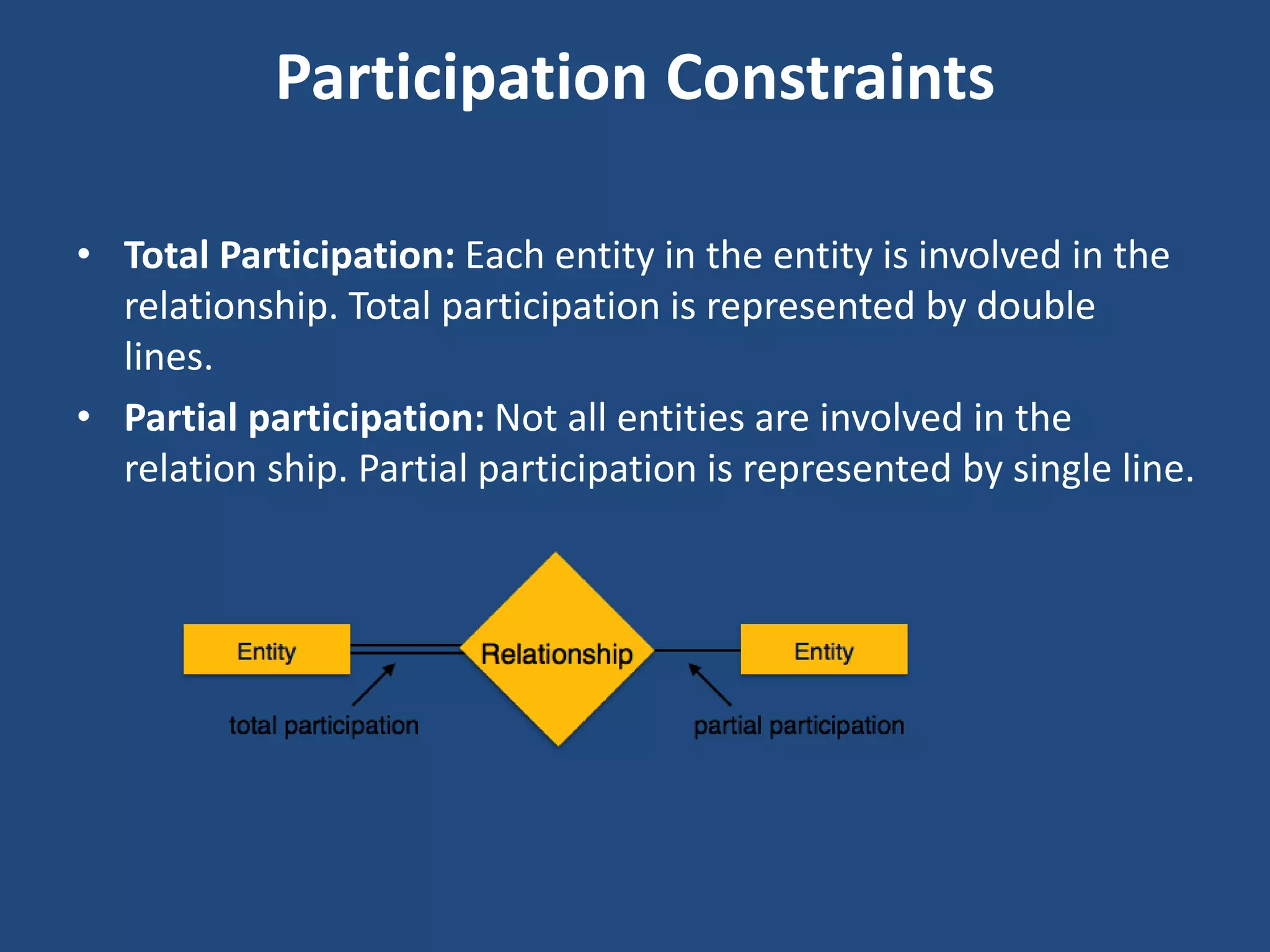
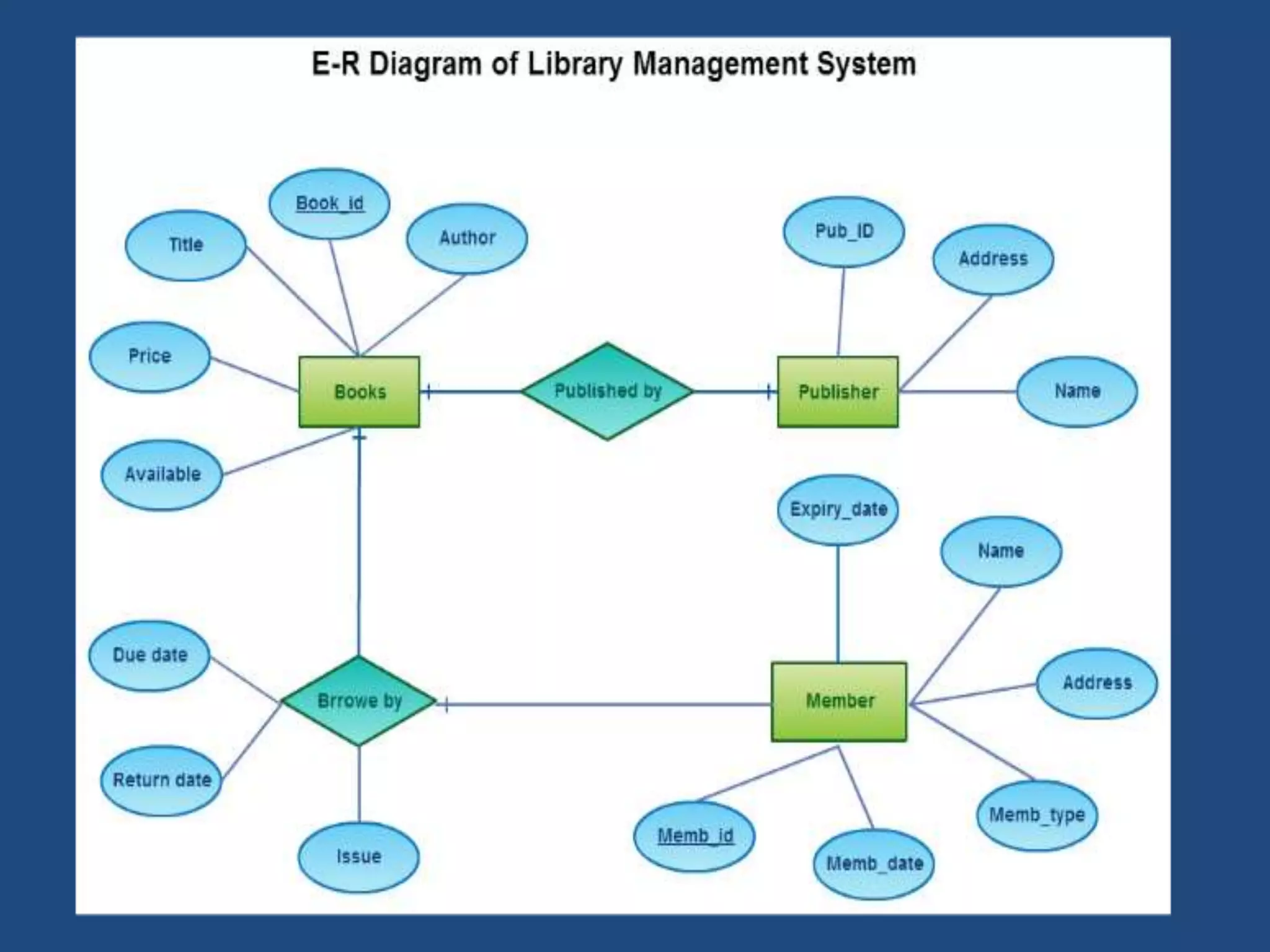
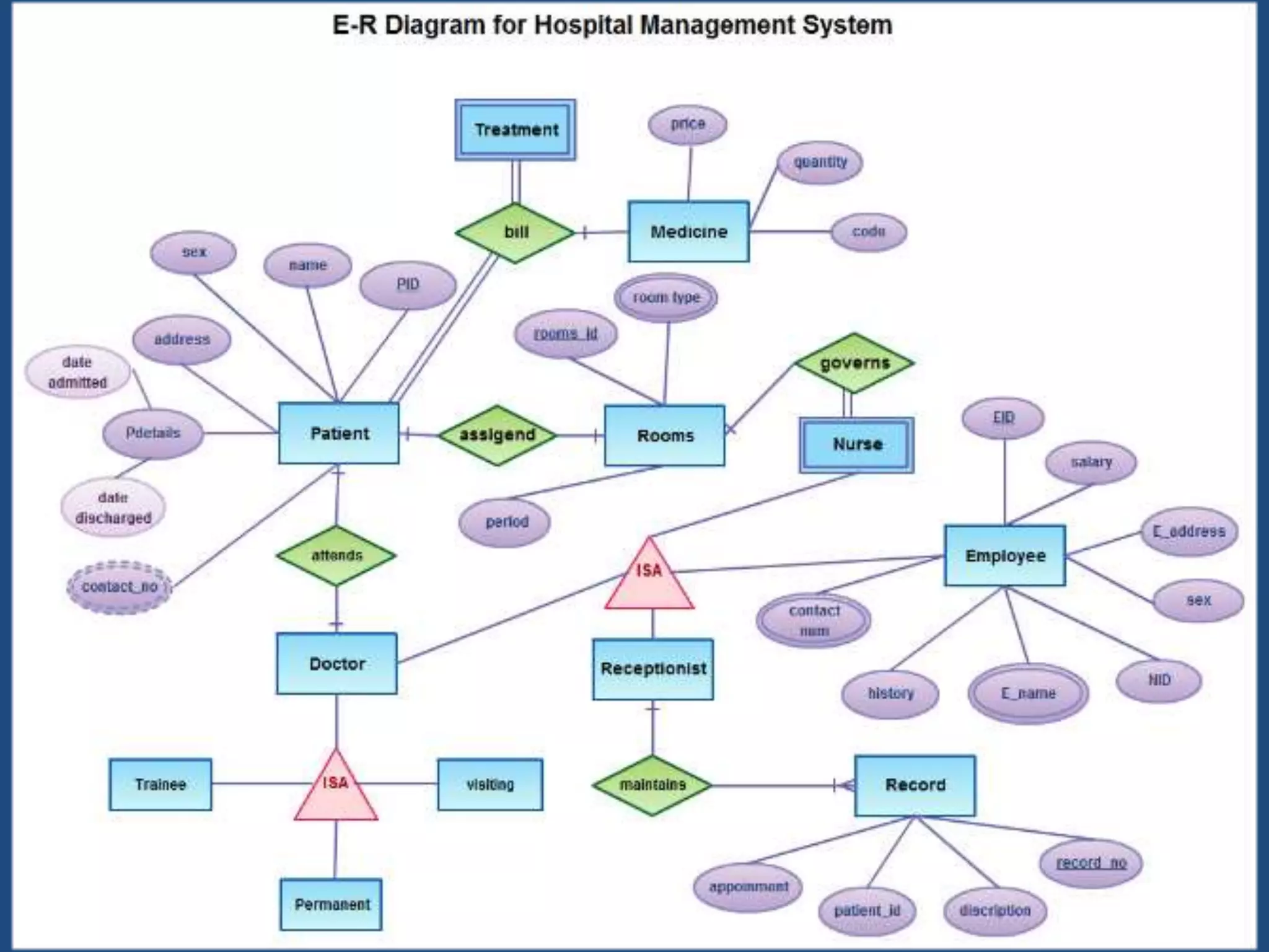
Entity Relationship Diagrams 
Prof. Sadique Nayeem
ER diagrams 
• ER-modeling is a data modeling technique used in software 
engineering to produce a conceptual data model of a 
information system. 
• Diagrams created using this ER-modeling technique are called 
Entity-Relationship Diagrams, or ER diagrams or ERDs.
Entity 
• Entities are represented by means of rectangles. 
Rectangles are named with the entity set they 
represent. 
Entities in a school database
Attributes 
• Attributes are properties of entities. Attributes are 
represented by means of eclipses. Every eclipse represents 
one attribute and is directly connected to its entity 
(rectangle).
composite attributes 
• If the attributes are composite, they are further divided in a 
tree like structure. Every node is then connected to its 
attribute. That is composite attributes are represented by 
eclipses that are connected with an eclipse.
Multivalued attributes 
• Multivalued attributes are depicted by double eclipse.
Derived attributes 
• Derived attributes are depicted by dashed eclipse.
Relationship 
• Relationships are represented by diamond shaped 
box. Name of the relationship is written in the 
diamond-box. All entities (rectangles), participating 
in relationship, are connected to it by a line.
Binary relationship and cardinality 
• A relationship where two entities are participating, is 
called a binary relationship. 
• Cardinality is the number of instance of an entity 
from a relation that can be associated with the 
relation.
One-to-one 
• When only one instance of entity is associated with the 
relationship, it is marked as '1'. This image below reflects that 
only 1 instance of each entity should be associated with the 
relationship. It depicts one-to-one relationship 
• The 1:1 (read as “one to one”) relationship means that one 
instance of the parent entity is associated with one instance 
of the child entity. 
Example: Employee of the month and parking for him.
One-to-many 
• When more than one instance of entity is associated with the relationship, 
it is marked as 'N'. This image below reflects that only 1 instance of entity 
on the left and more than one instance of entity on the right can be 
associated with the relationship. It depicts one-to-many relationship 
• In this kind of relationship, a single instance of a parent entity is 
associated with many instances of a child entity; however, the child entity 
instance is related to only one instance of the parent. 
Example:
Many-to-one 
• When more than one instance of entity is associated with the relationship, 
it is marked as 'N'. This image below reflects that more than one instance 
of entity on the left and only one instance of entity on the right can be 
associated with the relationship. It depicts many-to-one relationship. 
• In this case, many instances of a parent entity can relate to many instances 
of a child entity.
Many-to-many 
• This image below reflects that more than one instance of 
entity on the left and more than one instance of entity on the 
right can be associated with the relationship. It depicts many-to- 
many relationship
Participation Constraints 
• Total Participation: Each entity in the entity is involved in the 
relationship. Total participation is represented by double 
lines. 
• Partial participation: Not all entities are involved in the 
relation ship. Partial participation is represented by single line.
Codd's 12 Rules 
• Dr Edgar F. Codd did some extensive research in Relational Model of database 
systems and came up with twelve rules of his own which according to him, a 
database must obey in order to be a true relational database. 
• These rules can be applied on a database system that is capable of managing is 
stored data using only its relational capabilities. This is a foundation rule, which 
provides a base to imply other rules on it. 
• Rule 1: Information rule: This rule states that all information (data), which is 
stored in the database, must be a value of some table cell. Everything in a 
database must be stored in table formats. This information can be user data or 
meta-data. 
• Rule 2: Guaranteed Access rule: This rule states that every single data element 
(value) is guaranteed to be accessible logically with combination of table-name, 
primary-key (row value) and attribute-name (column value). No other means, such 
as pointers, can be used to access data. 
• Rule 3: Systematic Treatment of NULL values: This rule states the NULL values in 
the database must be given a systematic treatment. As a NULL may have several 
meanings, i.e. NULL can be interpreted as one the following: data is missing, data 
is not known, data is not applicable etc.
• Rule 4: Active online catalog: This rule states that the structure description of 
whole database must be stored in an online catalog, i.e. data dictionary, which can 
be accessed by the authorized users. Users can use the same query language to 
access the catalog which they use to access the database itself. 
• Rule 5: Comprehensive data sub-language rule :This rule states that a database 
must have a support for a language which has linear syntax which is capable of 
data definition, data manipulation and transaction management operations. 
Database can be accessed by means of this language only, either directly or by 
means of some application. If the database can be accessed or manipulated in 
some way without any help of this language, it is then a violation. 
• Rule 6: View updating rule: This rule states that all views of database, which can 
theoretically be updated, must also be updatable by the system. 
• Rule 7: High-level insert, update and delete rule: This rule states the database 
must employ support high-level insertion, updation and deletion. This must not be 
limited to a single row that is, it must also support union, intersection and minus 
operations to yield sets of data records. 
• Rule 8: Physical data independence: This rule states that the application should 
not have any concern about how the data is physically stored. Also, any change in 
its physical structure must not have any impact on application.
• Rule 9: Logical data independence: This rule states that the logical data must be 
independent of its user’s view (application). Any change in logical data must not 
imply any change in the application using it. For example, if two tables are merged 
or one is split into two different tables, there should be no impact the change on 
user application. This is one of the most difficult rule to apply. 
• Rule 10: Integrity independence: This rule states that the database must be 
independent of the application using it. All its integrity constraints can be 
independently modified without the need of any change in the application. This 
rule makes database independent of the front-end application and its interface. 
• Rule 11: Distribution independence: This rule states that the end user must not be 
able to see that the data is distributed over various locations. User must also see 
that data is located at one site only. This rule has been proven as a foundation of 
distributed database systems. 
• Rule 12: Non-subversion rule: This rule states that if a system has an interface that 
provides access to low level records, this interface then must not be able to 
subvert the system and bypass security and integrity constraints.
• http://www.tutorialspoint.com/dbms/er_diagram_representation.htm 
• http://www.databasedesign.co.uk/bookdatabasesafirstcourse/chap3/chap3.htm
Reference 
• Systems Analysis Design, 5th edition, A. Dennis, B. A. Wixom and R. M. 
Roth, John Wiley and sons.

Entity Relationship Diagrams

  • 1.
    Entity Relationship Diagrams Prof. Sadique Nayeem
  • 2.
    ER diagrams •ER-modeling is a data modeling technique used in software engineering to produce a conceptual data model of a information system. • Diagrams created using this ER-modeling technique are called Entity-Relationship Diagrams, or ER diagrams or ERDs.
  • 3.
    Entity • Entitiesare represented by means of rectangles. Rectangles are named with the entity set they represent. Entities in a school database
  • 4.
    Attributes • Attributesare properties of entities. Attributes are represented by means of eclipses. Every eclipse represents one attribute and is directly connected to its entity (rectangle).
  • 5.
    composite attributes •If the attributes are composite, they are further divided in a tree like structure. Every node is then connected to its attribute. That is composite attributes are represented by eclipses that are connected with an eclipse.
  • 6.
    Multivalued attributes •Multivalued attributes are depicted by double eclipse.
  • 7.
    Derived attributes •Derived attributes are depicted by dashed eclipse.
  • 8.
    Relationship • Relationshipsare represented by diamond shaped box. Name of the relationship is written in the diamond-box. All entities (rectangles), participating in relationship, are connected to it by a line.
  • 9.
    Binary relationship andcardinality • A relationship where two entities are participating, is called a binary relationship. • Cardinality is the number of instance of an entity from a relation that can be associated with the relation.
  • 10.
    One-to-one • Whenonly one instance of entity is associated with the relationship, it is marked as '1'. This image below reflects that only 1 instance of each entity should be associated with the relationship. It depicts one-to-one relationship • The 1:1 (read as “one to one”) relationship means that one instance of the parent entity is associated with one instance of the child entity. Example: Employee of the month and parking for him.
  • 11.
    One-to-many • Whenmore than one instance of entity is associated with the relationship, it is marked as 'N'. This image below reflects that only 1 instance of entity on the left and more than one instance of entity on the right can be associated with the relationship. It depicts one-to-many relationship • In this kind of relationship, a single instance of a parent entity is associated with many instances of a child entity; however, the child entity instance is related to only one instance of the parent. Example:
  • 12.
    Many-to-one • Whenmore than one instance of entity is associated with the relationship, it is marked as 'N'. This image below reflects that more than one instance of entity on the left and only one instance of entity on the right can be associated with the relationship. It depicts many-to-one relationship. • In this case, many instances of a parent entity can relate to many instances of a child entity.
  • 13.
    Many-to-many • Thisimage below reflects that more than one instance of entity on the left and more than one instance of entity on the right can be associated with the relationship. It depicts many-to- many relationship
  • 14.
    Participation Constraints •Total Participation: Each entity in the entity is involved in the relationship. Total participation is represented by double lines. • Partial participation: Not all entities are involved in the relation ship. Partial participation is represented by single line.
  • 15.
    Codd's 12 Rules • Dr Edgar F. Codd did some extensive research in Relational Model of database systems and came up with twelve rules of his own which according to him, a database must obey in order to be a true relational database. • These rules can be applied on a database system that is capable of managing is stored data using only its relational capabilities. This is a foundation rule, which provides a base to imply other rules on it. • Rule 1: Information rule: This rule states that all information (data), which is stored in the database, must be a value of some table cell. Everything in a database must be stored in table formats. This information can be user data or meta-data. • Rule 2: Guaranteed Access rule: This rule states that every single data element (value) is guaranteed to be accessible logically with combination of table-name, primary-key (row value) and attribute-name (column value). No other means, such as pointers, can be used to access data. • Rule 3: Systematic Treatment of NULL values: This rule states the NULL values in the database must be given a systematic treatment. As a NULL may have several meanings, i.e. NULL can be interpreted as one the following: data is missing, data is not known, data is not applicable etc.
  • 16.
    • Rule 4:Active online catalog: This rule states that the structure description of whole database must be stored in an online catalog, i.e. data dictionary, which can be accessed by the authorized users. Users can use the same query language to access the catalog which they use to access the database itself. • Rule 5: Comprehensive data sub-language rule :This rule states that a database must have a support for a language which has linear syntax which is capable of data definition, data manipulation and transaction management operations. Database can be accessed by means of this language only, either directly or by means of some application. If the database can be accessed or manipulated in some way without any help of this language, it is then a violation. • Rule 6: View updating rule: This rule states that all views of database, which can theoretically be updated, must also be updatable by the system. • Rule 7: High-level insert, update and delete rule: This rule states the database must employ support high-level insertion, updation and deletion. This must not be limited to a single row that is, it must also support union, intersection and minus operations to yield sets of data records. • Rule 8: Physical data independence: This rule states that the application should not have any concern about how the data is physically stored. Also, any change in its physical structure must not have any impact on application.
  • 17.
    • Rule 9:Logical data independence: This rule states that the logical data must be independent of its user’s view (application). Any change in logical data must not imply any change in the application using it. For example, if two tables are merged or one is split into two different tables, there should be no impact the change on user application. This is one of the most difficult rule to apply. • Rule 10: Integrity independence: This rule states that the database must be independent of the application using it. All its integrity constraints can be independently modified without the need of any change in the application. This rule makes database independent of the front-end application and its interface. • Rule 11: Distribution independence: This rule states that the end user must not be able to see that the data is distributed over various locations. User must also see that data is located at one site only. This rule has been proven as a foundation of distributed database systems. • Rule 12: Non-subversion rule: This rule states that if a system has an interface that provides access to low level records, this interface then must not be able to subvert the system and bypass security and integrity constraints.
  • 18.
    • http://www.tutorialspoint.com/dbms/er_diagram_representation.htm •http://www.databasedesign.co.uk/bookdatabasesafirstcourse/chap3/chap3.htm
  • 21.
    Reference • SystemsAnalysis Design, 5th edition, A. Dennis, B. A. Wixom and R. M. Roth, John Wiley and sons.