This document provides an overview of database management systems (DBMS) and SQL. It defines key concepts such as databases, DBMS, ER diagrams, entity sets, attributes, relationships, keys, functional dependencies, and database normalization. It explains that a DBMS is software that allows for storing, retrieving, and securing users' data and helps users and applications access and manage data in databases. The document also outlines common difficulties that DBMS were developed to address, such as data redundancy and integrity issues.
The document discusses different data models including hierarchical, network, relational, and object oriented models. It also provides details on entity-relationship (E-R) modeling. The E-R model defines entities and their attributes, and relationships between entities. Key concepts include entity sets, relationship sets, mapping cardinalities, participation constraints, keys, and designing E-R diagrams. An example E-R diagram for a university management system is presented to illustrate these concepts.
The document discusses different data models including hierarchical, network, relational, and object-oriented models. It also describes entity-relationship (E-R) modeling which involves defining entities, attributes, and relationships between entities. Key aspects of E-R modeling covered include entity types, relationship types, cardinalities, keys, and converting an E-R diagram into a relational database schema. The document provides examples to illustrate concepts such as weak entities, roles, and design considerations for E-R diagrams.
The document discusses key concepts of the relational database model including:
- Relations are represented as tables with rows and columns.
- Entities have attributes with domains and tuples represent rows.
- Relations have keys like candidate keys and foreign keys for integrity.
- Views are virtual relations defined by queries on base relations and allow customized access.
The document provides an overview of entity-relationship (ER) modeling and diagramming. It discusses key concepts like entities, attributes, relationships, cardinalities, keys, and weak entities. It also covers ER diagram components and symbols, including rectangles for entities, diamonds for relationships, and lines connecting them. The document aims to illustrate how ER diagrams define relationships between entities and help incorporate those relationships into the database design process.
The document presents information on Entity Relationship (ER) modeling for database design. It discusses the key concepts of ER modeling including entities, attributes, relationships and cardinalities. It also explains how to create an Entity Relationship Diagram (ERD) using standard symbols and notations. Additional features like generalization, specialization and inheritance are covered which allow ERDs to represent hierarchical relationships between entities. The presentation aims to provide an overview of ER modeling and ERDs as an important technique for conceptual database design.
This document presents information on the Entity-Relationship (ER) model for conceptual database design. It discusses key concepts of the ER model including entity sets, relationship sets, attributes, constraints, weak entity sets, and superclass/subclass relationships. It provides examples of how these concepts are represented in an ER diagram and outlines good principles for database design.
The document describes the key concepts of an Entity-Relationship (ER) model, which is a high-level conceptual data model representing logical relationships between entities (or objects) to develop an initial database design. The ER model was first proposed by Peter Chen in the 1970s and uses ER diagrams to represent entities with properties and relationships. Entities have attributes and exist in entity sets. Relationships exist between entity sets and have cardinality constraints. Weak entities depend on strong/identifying entities. The ER model includes other concepts like keys, participation constraints, degree of relationships, and extended features like generalization/specialization and aggregation.
The document discusses modeling data objects in an entity relationship diagram. It covers key concepts like entities, attributes, relationships, and keys. It provides examples of how to represent different types of relationships between entities like one-to-one, one-to-many, and many-to-many. The document also discusses modeling weak entities, documenting the ER diagram, normalizing the data to avoid anomalies, and determining the scope of the database and application system.
The document defines key concepts of an entity relationship (ER) model used for database design. It explains that an ER model uses entities, attributes, and relationships to conceptualize a database's structure and design. It provides examples of entity types like strong and weak entities, attribute types like primary keys and foreign keys, and relationship types like one-to-one, one-to-many, many-to-one, and many-to-many. The ER model develops a simple conceptual view of a database's data elements and how they relate to each other.
chapter 4-Functional Dependency and Normilization.pdfMisganawAbeje1
This chapter describe about the theory that has been developed with the goal of evaluating relational schemas for design quality , that is, to measure formally why one set of groupings of attributes into relation schemas is better than
another.
Islamic University Previous Year Question Solution 2019 (ADBMS)Rakibul Hasan Pranto
Database administrators (DBAs) manage databases and are responsible for tasks like creating the database schema, defining storage structures and access methods, modifying the schema or physical organization when needed, granting authorization for data access, and specifying integrity constraints. Other database roles include application programmers, sophisticated users, specialized users, standalone users, native users, and system analysts who are responsible for database design, structure, and properties.
This document provides an overview of relational database concepts including the relational data model, ER diagrams, normalization, and database languages. It discusses how data is organized in tables with attributes, tuples, domains, and keys in the relational model. ER diagrams are used to conceptualize relationships between entities and attributes. Normalization is the process of structuring data to minimize redundancy through various normal forms up to 3NF. Common database languages are also summarized including DDL, DML, DCL, and TCL and their uses.
Entity Relationship modeling is used to define relationships between entities in a database. It involves creating Entity Relationship Diagrams which use entities, attributes, and relationships to represent how data is connected. The ER diagram defines the entities, their attributes, and the relationships between entities. This modeling helps with database design and implementation by illustrating how data is structured and related.
The document discusses database design and normalization. It covers key concepts in database design including the entity-relationship model, normalization forms, functional dependencies, and multi-valued dependencies. The goal of normalization is to organize data to reduce redundancy and dependency issues by decomposing tables to satisfy certain normal forms up to fifth normal form. Normalization involves identifying functional dependencies between attributes and ensuring tables comply with rules for each normal form.
The document discusses the relational data model and its key concepts. The relational model represents a database as a collection of relations (tables). Each row in a relation represents a tuple of related data values. Attributes describe the columns and domains define the possible values for each attribute. Relations have schemas that define the relation name and attributes. Relation states contain sets of tuples that must satisfy integrity constraints defined on the schema.
The document provides an introduction to SQL and database concepts. It discusses:
- What a database management system (DBMS) is and its importance for data management.
- An introduction to structured query language (SQL) as a standard language for interacting with relational databases.
- Key SQL concepts like data definition language, data manipulation language, and data control language.
- How to perform common SQL operations like creating databases and tables, inserting, updating, and deleting data, and using joins and aggregation functions.
The document provides an overview of entity relationship modeling and SQL. It defines key concepts like entities, attributes, relationships and cardinalities. It also explains how these concepts are represented in an entity relationship diagram using standard symbols like rectangles for entities and diamonds for relationships. Specific examples of one-to-one, one-to-many and many-to-one relationships are illustrated. The document aims to introduce fundamental database and data modeling principles.
SQL Tutorial - Basics of Structured Query Language Day 1.pdfRiturajDas28
This document provides an overview of SQL and database concepts. It defines what a database is and common database terminology like tables, rows, records, and fields. It describes the different types of database users and common database architectures like single-tier, two-tier, and three-tier. Entity-relationship modeling and database schemas are also explained, along with keys, relationships, and mapping cardinalities. The document concludes with a discussion of Codd's 12 rules for relational databases.
The document provides an overview of conceptual database design using entity-relationship (ER) modeling. It defines key concepts in ER diagrams like entities, attributes, relationships and their cardinalities. It explains how to model different relationship types like one-to-one, one-to-many and many-to-many. It also covers advanced topics such as weak entities, generalization, specialization and aggregation. The overall purpose is to illustrate how ER diagrams can be used to design databases by visually representing the entities, attributes, and relationships in a domain.
The document discusses entity relationship diagrams and database design concepts. It defines entities, entity sets, attributes, relationships and cardinalities. It explains the different types of keys such as candidate keys, primary keys and foreign keys. Primary keys uniquely identify each record in a table while foreign keys link records between tables. The document also covers participation constraints and weak entity sets.
The document discusses the entity-relationship (ER) model and relational data model for database design. It provides information on the key components of the ER model, including entities, attributes, relationships, keys, and cardinalities. It also describes how the ER model defines the conceptual view of a database using real-world entities and relationships. Additionally, it covers the basics of the relational data model, which uses tables, rows, columns, keys, and relationships between tables to organize data.
A database is a collection of logically related data organized for convenient access, usually by programs for specific purposes. A DBMS is software that allows users to define, construct and manipulate databases for various applications. The database and DBMS together form a database system. A DBMS provides advantages like reducing data redundancy and inconsistency, restricting unauthorized access, and enforcing data integrity and security.
The document provides an overview of entity-relationship (ER) modeling concepts used in database design. It defines key terms like entities, attributes, relationships, and cardinalities. It explains how ER diagrams visually represent these concepts using symbols like rectangles, diamonds, and lines. The document also discusses entity types, relationship degrees, key attributes, weak entities, and how to model one-to-one, one-to-many, many-to-one, and many-to-many relationships. Overall, the document serves as a guide to basic ER modeling principles for conceptual database design.
The document discusses key concepts of the relational database model including how tables represent data through relations, attributes, tuples, and domains. It defines primary keys, foreign keys, entity integrity and referential integrity. Views are described as virtual relations defined by queries on base relations that dynamically reflect changes to the underlying data. The purpose of views is to provide security, customization of data access, and simplification of complex queries. There are restrictions on updating data through views.
Rainfall intensity duration frequency curve statistical analysis and modeling...bijceesjournal
Using data from 41 years in Patna’ India’ the study’s goal is to analyze the trends of how often it rains on a weekly, seasonal, and annual basis (1981−2020). First, utilizing the intensity-duration-frequency (IDF) curve and the relationship by statistically analyzing rainfall’ the historical rainfall data set for Patna’ India’ during a 41 year period (1981−2020), was evaluated for its quality. Changes in the hydrologic cycle as a result of increased greenhouse gas emissions are expected to induce variations in the intensity, length, and frequency of precipitation events. One strategy to lessen vulnerability is to quantify probable changes and adapt to them. Techniques such as log-normal, normal, and Gumbel are used (EV-I). Distributions were created with durations of 1, 2, 3, 6, and 24 h and return times of 2, 5, 10, 25, and 100 years. There were also mathematical correlations discovered between rainfall and recurrence interval.
Findings: Based on findings, the Gumbel approach produced the highest intensity values, whereas the other approaches produced values that were close to each other. The data indicates that 461.9 mm of rain fell during the monsoon season’s 301st week. However, it was found that the 29th week had the greatest average rainfall, 92.6 mm. With 952.6 mm on average, the monsoon season saw the highest rainfall. Calculations revealed that the yearly rainfall averaged 1171.1 mm. Using Weibull’s method, the study was subsequently expanded to examine rainfall distribution at different recurrence intervals of 2, 5, 10, and 25 years. Rainfall and recurrence interval mathematical correlations were also developed. Further regression analysis revealed that short wave irrigation, wind direction, wind speed, pressure, relative humidity, and temperature all had a substantial influence on rainfall.
Originality and value: The results of the rainfall IDF curves can provide useful information to policymakers in making appropriate decisions in managing and minimizing floods in the study area.
Embedded machine learning-based road conditions and driving behavior monitoringIJECEIAES
Car accident rates have increased in recent years, resulting in losses in human lives, properties, and other financial costs. An embedded machine learning-based system is developed to address this critical issue. The system can monitor road conditions, detect driving patterns, and identify aggressive driving behaviors. The system is based on neural networks trained on a comprehensive dataset of driving events, driving styles, and road conditions. The system effectively detects potential risks and helps mitigate the frequency and impact of accidents. The primary goal is to ensure the safety of drivers and vehicles. Collecting data involved gathering information on three key road events: normal street and normal drive, speed bumps, circular yellow speed bumps, and three aggressive driving actions: sudden start, sudden stop, and sudden entry. The gathered data is processed and analyzed using a machine learning system designed for limited power and memory devices. The developed system resulted in 91.9% accuracy, 93.6% precision, and 92% recall. The achieved inference time on an Arduino Nano 33 BLE Sense with a 32-bit CPU running at 64 MHz is 34 ms and requires 2.6 kB peak RAM and 139.9 kB program flash memory, making it suitable for resource-constrained embedded systems.
Software Engineering and Project Management - Introduction, Modeling Concepts...Prakhyath Rai
Introduction, Modeling Concepts and Class Modeling: What is Object orientation? What is OO development? OO Themes; Evidence for usefulness of OO development; OO modeling history. Modeling
as Design technique: Modeling, abstraction, The Three models. Class Modeling: Object and Class Concept, Link and associations concepts, Generalization and Inheritance, A sample class model, Navigation of class models, and UML diagrams
Building the Analysis Models: Requirement Analysis, Analysis Model Approaches, Data modeling Concepts, Object Oriented Analysis, Scenario-Based Modeling, Flow-Oriented Modeling, class Based Modeling, Creating a Behavioral Model.
Prediction of Electrical Energy Efficiency Using Information on Consumer's Ac...PriyankaKilaniya
Energy efficiency has been important since the latter part of the last century. The main object of this survey is to determine the energy efficiency knowledge among consumers. Two separate districts in Bangladesh are selected to conduct the survey on households and showrooms about the energy and seller also. The survey uses the data to find some regression equations from which it is easy to predict energy efficiency knowledge. The data is analyzed and calculated based on five important criteria. The initial target was to find some factors that help predict a person's energy efficiency knowledge. From the survey, it is found that the energy efficiency awareness among the people of our country is very low. Relationships between household energy use behaviors are estimated using a unique dataset of about 40 households and 20 showrooms in Bangladesh's Chapainawabganj and Bagerhat districts. Knowledge of energy consumption and energy efficiency technology options is found to be associated with household use of energy conservation practices. Household characteristics also influence household energy use behavior. Younger household cohorts are more likely to adopt energy-efficient technologies and energy conservation practices and place primary importance on energy saving for environmental reasons. Education also influences attitudes toward energy conservation in Bangladesh. Low-education households indicate they primarily save electricity for the environment while high-education households indicate they are motivated by environmental concerns.
DEEP LEARNING FOR SMART GRID INTRUSION DETECTION: A HYBRID CNN-LSTM-BASED MODELijaia
As digital technology becomes more deeply embedded in power systems, protecting the communication
networks of Smart Grids (SG) has emerged as a critical concern. Distributed Network Protocol 3 (DNP3)
represents a multi-tiered application layer protocol extensively utilized in Supervisory Control and Data
Acquisition (SCADA)-based smart grids to facilitate real-time data gathering and control functionalities.
Robust Intrusion Detection Systems (IDS) are necessary for early threat detection and mitigation because
of the interconnection of these networks, which makes them vulnerable to a variety of cyberattacks. To
solve this issue, this paper develops a hybrid Deep Learning (DL) model specifically designed for intrusion
detection in smart grids. The proposed approach is a combination of the Convolutional Neural Network
(CNN) and the Long-Short-Term Memory algorithms (LSTM). We employed a recent intrusion detection
dataset (DNP3), which focuses on unauthorized commands and Denial of Service (DoS) cyberattacks, to
train and test our model. The results of our experiments show that our CNN-LSTM method is much better
at finding smart grid intrusions than other deep learning algorithms used for classification. In addition,
our proposed approach improves accuracy, precision, recall, and F1 score, achieving a high detection
accuracy rate of 99.50%.
Null Bangalore | Pentesters Approach to AWS IAMDivyanshu
#Abstract:
- Learn more about the real-world methods for auditing AWS IAM (Identity and Access Management) as a pentester. So let us proceed with a brief discussion of IAM as well as some typical misconfigurations and their potential exploits in order to reinforce the understanding of IAM security best practices.
- Gain actionable insights into AWS IAM policies and roles, using hands on approach.
#Prerequisites:
- Basic understanding of AWS services and architecture
- Familiarity with cloud security concepts
- Experience using the AWS Management Console or AWS CLI.
- For hands on lab create account on [killercoda.com](https://killercoda.com/cloudsecurity-scenario/)
# Scenario Covered:
- Basics of IAM in AWS
- Implementing IAM Policies with Least Privilege to Manage S3 Bucket
- Objective: Create an S3 bucket with least privilege IAM policy and validate access.
- Steps:
- Create S3 bucket.
- Attach least privilege policy to IAM user.
- Validate access.
- Exploiting IAM PassRole Misconfiguration
-Allows a user to pass a specific IAM role to an AWS service (ec2), typically used for service access delegation. Then exploit PassRole Misconfiguration granting unauthorized access to sensitive resources.
- Objective: Demonstrate how a PassRole misconfiguration can grant unauthorized access.
- Steps:
- Allow user to pass IAM role to EC2.
- Exploit misconfiguration for unauthorized access.
- Access sensitive resources.
- Exploiting IAM AssumeRole Misconfiguration with Overly Permissive Role
- An overly permissive IAM role configuration can lead to privilege escalation by creating a role with administrative privileges and allow a user to assume this role.
- Objective: Show how overly permissive IAM roles can lead to privilege escalation.
- Steps:
- Create role with administrative privileges.
- Allow user to assume the role.
- Perform administrative actions.
- Differentiation between PassRole vs AssumeRole
Try at [killercoda.com](https://killercoda.com/cloudsecurity-scenario/)
Applications of artificial Intelligence in Mechanical Engineering.pdfAtif Razi
Historically, mechanical engineering has relied heavily on human expertise and empirical methods to solve complex problems. With the introduction of computer-aided design (CAD) and finite element analysis (FEA), the field took its first steps towards digitization. These tools allowed engineers to simulate and analyze mechanical systems with greater accuracy and efficiency. However, the sheer volume of data generated by modern engineering systems and the increasing complexity of these systems have necessitated more advanced analytical tools, paving the way for AI.
AI offers the capability to process vast amounts of data, identify patterns, and make predictions with a level of speed and accuracy unattainable by traditional methods. This has profound implications for mechanical engineering, enabling more efficient design processes, predictive maintenance strategies, and optimized manufacturing operations. AI-driven tools can learn from historical data, adapt to new information, and continuously improve their performance, making them invaluable in tackling the multifaceted challenges of modern mechanical engineering.
Discover the latest insights on Data Driven Maintenance with our comprehensive webinar presentation. Learn about traditional maintenance challenges, the right approach to utilizing data, and the benefits of adopting a Data Driven Maintenance strategy. Explore real-world examples, industry best practices, and innovative solutions like FMECA and the D3M model. This presentation, led by expert Jules Oudmans, is essential for asset owners looking to optimize their maintenance processes and leverage digital technologies for improved efficiency and performance. Download now to stay ahead in the evolving maintenance landscape.
Build the Next Generation of Apps with the Einstein 1 Platform.
Rejoignez Philippe Ozil pour une session de workshops qui vous guidera à travers les détails de la plateforme Einstein 1, l'importance des données pour la création d'applications d'intelligence artificielle et les différents outils et technologies que Salesforce propose pour vous apporter tous les bénéfices de l'IA.
AI + Data Community Tour - Build the Next Generation of Apps with the Einstei...
DBMS & SQL Notes .pdf
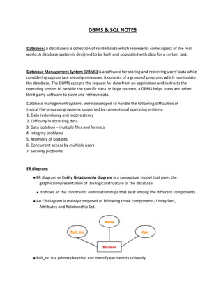
1. DBMS & SQL NOTES
Database: A database is a collection of related data which represents some aspect of the real
world. A database system is designed to be built and populated with data for a certain task.
Database Management System (DBMS) is a software for storing and retrieving users' data while
considering appropriate security measures. It consists of a group of programs which manipulate
the database. The DBMS accepts the request for data from an application and instructs the
operating system to provide the specific data. In large systems, a DBMS helps users and other
third-party software to store and retrieve data.
Database management systems were developed to handle the following difficulties of
typical File-processing systems supported by conventional operating systems.
1. Data redundancy and inconsistency
2. Difficulty in accessing data
3. Data isolation – multiple files and formats
4. Integrity problems
5. Atomicity of updates
6. Concurrent access by multiple users
7. Security problems
ER diagram:
● ER diagram or Entity Relationship diagram is a conceptual model that gives the
graphical representation of the logical structure of the database.
● It shows all the constraints and relationships that exist among the different components.
● An ER diagram is mainly composed of following three components- Entity Sets,
Attributes and Relationship Set.
● Roll_no is a primary key that can identify each entity uniquely.
2. ● Thus, by using a student's roll number, a student can be identified uniquely.
Entity Set:
An entity set is a set of the same type of entities.
● Strong Entity Set:
o A strong entity set is an entity set that contains sufficient attributes to uniquely
identify all its entities.
o In other words, a primary key exists for a strong entity set.
o Primary key of a strong entity set is represented by underlining it.
● Weak Entity Set:
o A weak entity set is an entity set that does not contain sufficient attributes to
uniquely identify its entities.
o In other words, a primary key does not exist for a weak entity set.
o However, it contains a partial key called a discriminator.
o Discriminator can identify a group of entities from the entity set.
o Discriminator is represented by underlining with a dashed line.
Relationship:
A relationship is defined as an association among several entities.
● Unary Relationship Set - Unary relationship set is a relationship set where only one
entity set participates in a relationship set.
● Binary Relationship Set - Binary relationship set is a relationship set where two entity
sets participate in a relationship set.
● Ternary Relationship Set - Ternary relationship set is a relationship set where three
entity sets participate in a relationship set.
● N-ary Relationship Set - N-ary relationship set is a relationship set where ‘n’ entity sets
participate in a relationship set.
Cardinality Constraint:
Cardinality constraint defines the maximum number of relationship instances in which an entity
can participate.
● One-to-One Cardinality - An entity in set A can be associated with at most one entity in
set B. An entity in set B can be associated with at most one entity in set A.
● One-to-Many Cardinality - An entity in set A can be associated with any number (zero or
3. more) of entities in set B. An entity in set B can be associated with at most one entity in
set A.
● Many-to-One Cardinality - An entity in set A can be associated with at most one entity in
set B. An entity in set B can be associated with any number of entities in set A. ●
Many-to-Many Cardinality - An entity in set A can be associated with any number (zero or
more) of entities in set B. An entity in set B can be associated with any number (zero or
more) of entities in set A.
Attributes:
Attributes are the descriptive properties which are owned by each entity of an Entity Set.
Types of Attributes:
● Simple Attributes - Simple attributes are those attributes which cannot be divided
further. Ex. Age
● Composite Attributes - Composite attributes are those attributes which are composed
of many other simple attributes. Ex. Name, Address
● Multi Valued Attributes - Multi valued attributes are those attributes which can take
more than one value for a given entity from an entity set. Ex. Mobile No, Email ID ●
Derived Attributes - Derived attributes are those attributes which can be derived from
other attribute(s). Ex. Age can be derived from DOB.
● Key Attributes - Key attributes are those attributes which can identify an entity uniquely
in an entity set. Ex. Roll No.
Constraints:
Relational constraints are the restrictions imposed on the database contents and
operations. They ensure the correctness of data in the database.
● Domain Constraint - Domain constraint defines the domain or set of values for an
attribute. It specifies that the value taken by the attribute must be the atomic value from
its domain.
● Tuple Uniqueness Constraint - Tuple Uniqueness constraint specifies that all the tuples
must be necessarily unique in any relation.
● Key Constraint - All the values of the primary key must be unique. The value of the
primary key must not be null.
● Entity Integrity Constraint - Entity integrity constraint specifies that no attribute of
primary key must contain a null value in any relation.
● Referential Integrity Constraint - It specifies that all the values taken by the foreign key
4. must either be available in the relation of the primary key or be null.
Closure of an Attribute Set:
The set of all those attributes which can be functionally determined from an attribute set is
called a closure of that attribute set.
Keys:
A key is a set of attributes that can identify each tuple uniquely in the given relation.
Types of Keys:
● Super Key - A superkey is a set of attributes that can identify each tuple uniquely in the
given relation. A super key may consist of any number of attributes.
● Candidate Key - A set of minimal attribute(s) that can identify each tuple uniquely in the
given relation is called a candidate key.
● Primary Key - A primary key is a candidate key that the database designer selects while
designing the database. Primary Keys are unique and NOT NULL.
● Alternate Key - Candidate keys that are left unimplemented or unused after
implementing the primary key are called as alternate keys.
● Foreign Key - An attribute ‘X’ is called as a foreign key to some other attribute ‘Y’ when its
values are dependent on the values of attribute ‘Y’. The relation in which attribute ‘Y’ is
present is called as the referenced relation. The relation in which attribute ‘X’ is present
is called as the referencing relation.
● Composite Key - A primary key composed of multiple attributes and not just a single
attribute is called a composite key.
● Unique Key - It is unique for all the records of the table. Once assigned, its value cannot
be changed i.e. it is non-updatable. It may have a NULL value.
Functional Dependency:
In any relation, a functional dependency α → β holds if- Two tuples having same value
5. of attribute α also have same value for attribute β.
Types of Functional Dependency:
● Trivial Functional Dependencies –
o A functional dependency X → Y is said to be trivial if and only if Y ⊆ X. o
Thus, if RHS of a functional dependency is a subset of LHS, then it is called a
trivial functional dependency.
● Non-Trivial Functional Dependencies –
o A functional dependency X → Y is said to be non-trivial if and only if Y ⊄ X. o
Thus, if there exists at least one attribute in the RHS of a functional dependency
that is not a part of LHS, then it is called a non-trivial functional dependency.
Decomposition of a Relation:
The process of breaking up or dividing a single relation into two or more sub relations is called
the decomposition of a relation.
Properties of Decomposition:
● Lossless Decomposition - Lossless decomposition ensures
o No information is lost from the original relation during decomposition. o When
the sub relations are joined back, the same relation is obtained that was
decomposed.
● Dependency Preservation - Dependency preservation ensures
o None of the functional dependencies that hold on the original relation are lost. o
The sub relations still hold or satisfy the functional dependencies of the original
relation.
Types of Decomposition:
● Lossless Join Decomposition:
o Consider there is a relation R which is decomposed into sub relations R1, R2, ….,
Rn.
o This decomposition is called lossless join decomposition when the join of the sub
relations results in the same relation R that was decomposed.
o For lossless join decomposition, we always have- R1 ⋈ R2 ⋈ R3 ……. ⋈ Rn = R
where ⋈ is a natural join operator
● Lossy Join Decomposition:
o Consider there is a relation R which is decomposed into sub relations R1, R2, ….,
Rn.
o This decomposition is called lossy join decomposition when the join of the sub
6. relations does not result in the same relation R that was decomposed.
o For lossy join decomposition, we always have- R1 ⋈ R2 ⋈ R3 ……. ⋈ Rn ⊃ R
where ⋈ is a natural join operator
Normalization:
In DBMS, database normalization is a process of making the database consistent by-
● Reducing the redundancies
● Ensuring the integrity of data through lossless decomposition
Normal Forms:
● First Normal Form (1NF) - A given relation is called in First Normal Form (1NF) if each cell
of the table contains only an atomic value i.e. if the attribute of every tuple is either
single valued or a null value.
● Second Normal Form (2NF) - A given relation is called in Second Normal Form (2NF) if
and only if
o Relation already exists in 1NF.
o No partial dependency exists in the relation.
A → B is called a partial dependency if and only if- A is a subset of some
candidate key and B is a non-prime attribute.
● Third Normal Form (3NF) - A given relation is called in Third Normal Form (3NF) if and
only if
o Relation already exists in 2NF.
o No transitive dependency exists for non-prime attributes.
A → B is called a transitive dependency if and only if- A is not a super key and B
is a non-prime attribute.
● Boyce-Codd Normal Form - A given relation is called in BCNF if and only if
o Relation already exists in 3NF.
o For each non-trivial functional dependency ‘A → B’, A is a super key of the
relation.
7. Transaction:
Transaction is a single logical unit of work formed by a set of operations.
Operations in Transaction:
● Read Operation - Read(A) instruction will read the value of ‘A’ from the database and
will store it in the buffer in main memory.
● Write Operation – Write(A) will write the updated value of ‘A’ from the buffer to the
database.
Transaction States:
● Active State –
o This is the first state in the life cycle of a transaction.
o A transaction is called in an active state as long as its instructions are getting
executed.
o All the changes made by the transaction now are stored in the buffer in main
memory.
● Partially Committed State –
o After the last instruction of the transaction has been executed, it enters into a
partially committed state.
o After entering this state, the transaction is considered to be partially committed.
o It is not considered fully committed because all the changes made by the
transaction are still stored in the buffer in main memory.
● Committed State –
o After all the changes made by the transaction have been successfully stored into
the database, it enters into a committed state.
o Now, the transaction is considered to be fully committed.
● Failed State –
o When a transaction is getting executed in the active state or partially committed
state and some failure occurs due to which it becomes impossible to continue
the execution, it enters into a failed state.
8. ● Aborted State –
o After the transaction has failed and entered into a failed state, all the changes
made by it have to be undone.
o To undo the changes made by the transaction, it becomes necessary to roll back
the transaction.
o After the transaction has rolled back completely, it enters into an aborted state.
● Terminated State –
o This is the last state in the life cycle of a transaction.
o After entering the committed state or aborted state, the transaction finally
enters into a terminated state where its life cycle finally comes to an end.
ACID Properties:
To ensure the consistency of the database, certain properties are followed by all the
transactions occurring in the system. These properties are called as ACID Properties of a
transaction.
● Atomicity –
o This property ensures that either the transaction occurs completely or it does not
occur at all.
o In other words, it ensures that no transaction occurs partially.
● Consistency –
o This property ensures that integrity constraints are maintained.
o In other words, it ensures that the database remains consistent before and after
the transaction.
● Isolation –
o This property ensures that multiple transactions can occur simultaneously
without causing any inconsistency.
o The resultant state of the system after executing all the transactions is the same
as the state that would be achieved if the transactions were executed serially one
after the other.
● Durability –
o This property ensures that all the changes made by a transaction after its
successful execution are written successfully to the disk.
o It also ensures that these changes exist permanently and are never lost even if
there occurs a failure of any kind.
Schedules:
9. The order in which the operations of multiple transactions appear for execution is called as a
schedule.
● Serial Schedules –
o All the transactions execute serially one after the other.
o When one transaction executes, no other transaction is allowed to execute.
o Serial schedules are always- Consistent, Recoverable, Cascadeless and Strict. ●
Non-Serial Schedules –
o Multiple transactions execute concurrently.
o Operations of all the transactions are inter leaved or mixed with each other.
o Non-serial schedules are not always- Consistent, Recoverable, Cascadeless and
Strict.
Serializability –
● Some non-serial schedules may lead to inconsistency of the database. ● Serializability
is a concept that helps to identify which non-serial schedules are correct and will
maintain the consistency of the database.
● Serializable Schedules –
o If a given non-serial schedule of ‘n’ transactions is equivalent to some serial
schedule of ‘n’ transactions, then it is called as a serializable schedule.
o Serializable schedules are always- Consistent, Recoverable, Cascadeless and
Strict.
10. Types of Serializability –
● Conflict Serializability - If a given non-serial schedule can be converted into a serial
schedule by swapping its non-conflicting operations, then it is called a conflict
serializable schedule.
● View Serializability - If a given schedule is found to be viewed as equivalent to some
serial schedule, then it is called a view serializable schedule.
Non-Serializable Schedules –
● A non-serial schedule which is not serializable is called a non-serializable schedule. ● A
non-serializable schedule is not guaranteed to produce the same effect as produced by
some serial schedule on any consistent database.
● Non-serializable schedules- may or may not be consistent, may or may not be
recoverable.
● Irrecoverable Schedules –
If in a schedule,
o A transaction performs a dirty read operation from an uncommitted transaction
o And commits before the transaction from which it has read the value then such a
schedule is known as an Irrecoverable Schedule.
● Recoverable Schedules –
If in a schedule,
o A transaction performs a dirty read operation from an uncommitted transaction
o And its commit operation is delayed till the uncommitted transaction either
commits or roll backs
then such a schedule is known as a Recoverable Schedule.
Types of Recoverable Schedules –
● Cascading Schedule - If in a schedule, failure of one transaction causes several other
dependent transactions to rollback or abort, then such a schedule is called as a
Cascading Schedule or Cascading Rollback or Cascading Abort.
● Cascadeless Schedule - If in a schedule, a transaction is not allowed to read a data item
until the last transaction that has written it is committed or aborted, then such a
schedule is called as a Cascadeless Schedule.
● Strict Schedule - If in a schedule, a transaction is neither allowed to read nor write a data
item until the last transaction that has written it is committed or aborted, then such a
schedule is called as a Strict Schedule.
11. Relational Algebra:
Relational Algebra is a procedural query language which takes a relation as an input and
generates a relation as an output.
Basic Operator Semantic
σ(Selection) Select rows based on given condition
∏(Projection) Project some columns
X (Cross Product) Cross product of relations, returns m*n rows where m and n
are number of rows in R1 and R2 respectively.
U (Union) Return those tuples which are either in R1 or in R2. Max no.
of rows returned = m+n and Min no. of rows returned =
max(m,n)
−(Minus) R1-R2 returns those tuples which are in R1 but not in R2.
Max no. of rows returned = m and Min no. of rows
returned = m-n
ρ(Rename) Renaming a relation to another relation.
Extended Operator Semantic
∩ (Intersection) Returns those tuples which are in both R1 and R2. Max no.
of rows returned = min(m,n) and Min no. of rows returned
= 0
⋈c(Conditional Join) Selection from two or more tables based on some
condition (Cross product followed by selection)
⋈(Equi Join) It is a special case of conditional join when only
equality conditions are applied between attributes.
⋈(Natural Join) In natural join, equality conditions on common attributes
hold and duplicate attributes are removed by default.
Note: Natural Join is equivalent to cross product if two
relations have no attribute in common and natural join of a
relation R with itself will return R only.
12. ⟕(Left Outer Join) When applying join on two relations R and S, some tuples of R
or S do not appear in the result set which does not satisfy the
join conditions. But Left Outer Joins gives all tuples of R in the
result set. The tuples of R which do not satisfy the join
condition will have values as NULL for attributes of S.
⟖(Right Outer Join) When applying join on two relations R and S, some tuples of R
or S do not appear in the result set which does not satisfy the
join conditions. But Right Outer Joins gives all tuples of S in
the result set. The tuples of S which do not satisfy the join
condition will have values as NULL for attributes of R.
⟗(Full Outer Join)
/(Division Operator)
When applying join on two relations R and S, some tuples of R
or S do not appear in the result set which does not satisfy the
join conditions. But Full Outer Joins gives all tuples of S and all
tuples of R in the result set. The tuples of S which do not
satisfy the join condition will have values as NULL for
attributes of R and vice versa.
Division operator A/B will return those tuples in A which are
associated with every tuple of B. Note: Attributes of B should
be a proper subset of attributes of A. The attributes in A/B will
be Attributes of A- Attribute of B.
File Structures:
● Primary Index: A primary index is an ordered file, records of fixed length with two fields.
First field is the same as the primary key as a data file and the second field is a pointer to
the data block, where the key is available. The average number of block accesses using
index = log2 Bi + 1, where Bi = number of index blocks.
● Clustering Index: Clustering index is created on data file whose records are physically
ordered on a non-key field (called Clustering field).
● Secondary Index: Secondary index provides secondary means of accessing a file for
which primary access already exists.
B Trees
At every level , we have Key and Data Pointer and data pointer points to either block or record.
Properties of B-Trees:
Root of B-tree can have children between 2 and P, where P is Order of tree.
13. Order of tree – Maximum number of children a node can have.
Internal node can have children between ⌈ P/2 ⌉ and P
Internal node can have keys between ⌈ P/2 ⌉ – 1 and P-1
B+ Trees
In B+ trees, the structure of leaf and non-leaf are different, so their order is. Order of non-leaf
will be higher as compared to leaf nodes.
Searching time will be less in B+ trees, since it doesn’t have record pointers in non-leaf because
of which depth will decrease.
SQL
DDL:
DDL is short name of Data Definition Language, which deals with database schemas and
descriptions, of how the data should reside in the database.
● CREATE - to create a database and its objects like (table, index, views, store procedure,
function, and triggers)
● ALTER - alters the structure of the existing database
● DROP - delete objects from the database
● TRUNCATE - remove all records from a table, including all spaces allocated for the
records are removed
● RENAME - rename an object
DML:
DML is short name of Data Manipulation Language which deals with data manipulation and
includes most common SQL statements such SELECT, INSERT, UPDATE, DELETE, etc., and it is
used to store, modify, retrieve, delete and update data in a database.
● SELECT - retrieve data from a database
● INSERT - insert data into a table
● UPDATE - updates existing data within a table
● DELETE - Delete all records from a database table
● MERGE - UPSERT operation (insert or update)
14. DCL:
DCL is short name of Data Control Language which includes commands such as GRANT and
mostly concerned with rights, permissions and other controls of the database system.
● GRANT - allow users access privileges to the database
● REVOKE - withdraw users access privileges given by using the GRANT command
TCL:
TCL is short name of Transaction Control Language which deals with a transaction within a
database.
● COMMIT - commits a Transaction
● ROLLBACK - rollback a transaction in case of any error occurs
● SAVEPOINT - to roll back the transaction making points within groups
SQL:
SQL is a standard language for storing, manipulating and retrieving data in databases.
SELECT:
The SELECT statement is used to select data from a database.
Syntax -
● SELECT column1, column2, ...
FROM table_name;
● Here, column1, column2, ... are the field names of the table you want to select data
from. If you want to select all the fields available in the table, use the following syntax: ●
SELECT * FROM table_name;
Ex –
● SELECT CustomerName, City FROM Customers;
SELECT DISTINCT:
The SELECT DISTINCT statement is used to return only distinct (different) values.
Syntax –
15. ● SELECT DISTINCT column1, column2, ...
FROM table_name;
Ex –
● SELECT DISTINCT Country FROM Customers;
WHERE:
The WHERE clause is used to filter records.
Syntax –
● SELECT column1, column2, ...
FROM table_name
WHERE condition;
Ex –
● SELECT * FROM Customers
WHERE Country='Mexico';
Operator Description
= Equal
> Greater than
< Less than
>= Greater than or equal
<= Less than or equal
<> Not equal. Note: In some versions of SQL this operator may be written as !=
AND, OR and NOT:
The WHERE clause can be combined with AND, OR, and NOT operators.
The AND and OR operators are used to filter records based on more than one condition:
● The AND operator displays a record if all the conditions separated by AND are TRUE.
● The OR operator displays a record if any of the conditions separated by OR is TRUE.
The NOT operator displays a record if the condition(s) is NOT TRUE.
16. Syntax –
● SELECT column1, column2, ...
FROM table_name
WHERE condition1 AND condition2 AND condition3 ...;
● SELECT column1, column2, ...
FROM table_name
WHERE condition1 OR condition2 OR condition3 ...;
● SELECT column1, column2, ...
FROM table_name
WHERE NOT condition;
Ex –
● SELECT * FROM Customers
WHERE Country='Germany' AND City='Berlin';
● SELECT * FROM Customers
WHERE Country='Germany' AND (City='Berlin' OR City='München');
ORDER BY:
The ORDER BY keyword is used to sort the result-set in ascending or descending order.
The ORDER BY keyword sorts the records in ascending order by default. To sort the records in
descending order, use the DESC keyword.
Syntax –
● SELECT column1, column2, ...
FROM table_name
ORDER BY column1, column2, ... ASC|DESC;
Ex –
● SELECT * FROM Customers
ORDER BY Country;
● SELECT * FROM Customers
ORDER BY Country ASC, CustomerName DESC;
INSERT INTO:
The INSERT INTO statement is used to insert new records in a table.
17. Syntax –
● INSERT INTO table_name (column1, column2, column3, ...)
VALUES (value1, value2, value3, ...);
● INSERT INTO table_name
VALUES (value1, value2, value3, ...);
*In the second syntax, make sure the order of the values is in the same order as the columns in
the table.
Ex –
● INSERT INTO Customers (CustomerName, ContactName, Address, City, PostalCode,
Country)
VALUES ('Cardinal', 'Tom B. Erichsen', 'Skagen 21', 'Stavanger', '4006', 'Norway');
NULL Value:
It is not possible to test for NULL values with comparison operators, such as =, <, or
<>. We will have to use the IS NULL and IS NOT NULL operators instead.
Syntax –
● SELECT column_names
FROM table_name
WHERE column_name IS NULL;
● SELECT column_names
FROM table_name
WHERE column_name IS NOT NULL;
Ex –
● SELECT CustomerName, ContactName, Address
FROM Customers
WHERE Address IS NULL;
UPDATE:
The UPDATE statement is used to modify the existing records in a table.
Syntax –
● UPDATE table_name
18. SET column1 = value1, column2 = value2, ...
WHERE condition;
Ex –
● UPDATE Customers
SET ContactName = 'Alfred Schmidt', City= 'Frankfurt'
WHERE CustomerID = 1;
DELETE:
The DELETE statement is used to delete existing records in a table.
Syntax –
● DELETE FROM table_name WHERE condition;
● DELETE FROM table_name;
In 2nd
syntax, all rows are deleted. The table structure, attributes, and indexes will be intact
Ex –
● DELETE FROM Customers WHERE CustomerName='Alfreds Futterkiste';
SELECT TOP:
The SELECT TOP clause is used to specify the number of records to return.
Syntax –
● SELECT TOP number|percent column_name(s)
FROM table_name
WHERE condition;
● SELECT column_name(s)
FROM table_name
WHERE condition
LIMIT number;
● SELECT column_name(s)
FROM table_name
ORDER BY column_name(s)
FETCH FIRST number ROWS ONLY;
● SELECT column_name(s)
FROM table_name
WHERE ROWNUM <= number;
19. *In case the interviewer asks other than the TOP, rest are also correct. (Diff. DB Systems)
Ex –
● SELECT TOP 3 * FROM Customers;
● SELECT * FROM Customers
LIMIT 3;
● SELECT * FROM Customers
FETCH FIRST 3 ROWS ONLY;
Aggregate Functions:
MIN():
The MIN() function returns the smallest value of the selected column.
Syntax –
● SELECT MIN(column_name)
FROM table_name
WHERE condition;
Ex –
● SELECT MIN(Price) AS SmallestPrice
FROM Products;
MAX():
The MAX() function returns the largest value of the selected column.
Syntax –
● SELECT MAX(column_name)
FROM table_name
WHERE condition;
Ex –
● SELECT MAX(Price) AS LargestPrice
FROM Products;
COUNT():
The COUNT() function returns the number of rows that matches a specified criterion.
Syntax –
● SELECT COUNT(column_name)
20. FROM table_name
WHERE condition;
Ex –
● SELECT COUNT(ProductID)
FROM Products;
AVG():
The AVG() function returns the average value of a numeric column.
Syntax –
● SELECT AVG(column_name)
FROM table_name
WHERE condition;
Ex –
● SELECT AVG(Price)
FROM Products;
SUM():
The SUM() function returns the total sum of a numeric column.
Syntax –
● SELECT SUM(column_name)
FROM table_name
WHERE condition;
Ex –
● SELECT SUM(Quantity)
FROM OrderDetails;
LIKE Operator:
The LIKE operator is used in a WHERE clause to search for a specified pattern in a column.
There are two wildcards often used in conjunction with the LIKE operator:
● The percent sign (%) represents zero, one, or multiple characters
● The underscore sign (_) represents one, single character
Syntax –
21. ● SELECT column1, column2, ...
FROM table_name
WHERE columnN LIKE pattern;
LIKE Operator Description
WHERE CustomerName LIKE 'a%' Finds any values that start with "a"
WHERE CustomerName LIKE '%a' Finds any values that end with "a"
WHERE CustomerName LIKE '%or%' Finds any values that have "or" in any position
WHERE CustomerName LIKE '_r%' Finds any values that have "r" in the second position
WHERE CustomerName LIKE 'a_%' Finds any values that start with "a" and are at
least 2 characters in length
WHERE CustomerName LIKE 'a__%' Finds any values that start with "a" and are at
least 3 characters in length
WHERE ContactName LIKE 'a%o' Finds any values that start with "a" and ends with "o"
IN:
The IN operator allows you to specify multiple values in a WHERE clause.
The IN operator is a shorthand for multiple OR conditions.
Syntax –
● SELECT column_name(s)
FROM table_name
WHERE column_name IN (value1, value2, ...);
● SELECT column_name(s)
FROM table_name
WHERE column_name IN (SELECT STATEMENT);
Ex –
● SELECT * FROM Customers
WHERE Country IN ('Germany', 'France', 'UK');
● SELECT * FROM Customers
22. WHERE Country IN (SELECT Country FROM Suppliers);
BETWEEN:
The BETWEEN operator selects values within a given range. The values can be numbers, text, or
dates.
The BETWEEN operator is inclusive: begin and end values are included.
Syntax –
● SELECT column_name(s)
FROM table_name
WHERE column_name BETWEEN value1 AND value2;
Ex –
● SELECT * FROM Products
WHERE Price BETWEEN 10 AND 20;
Joins:
A JOIN clause is used to combine rows from two or more tables, based on a related column
between them.
INNER JOIN:
The INNER JOIN keyword selects records that have matching values in both tables.
Syntax –
● SELECT column_name(s)
FROM table1
INNER JOIN table2
ON table1.column_name = table2.column_name;
Ex –
● SELECT Orders.OrderID, Customers.CustomerName
FROM Orders
INNER JOIN Customers ON Orders.CustomerID = Customers.CustomerID;
LEFT (OUTER) JOIN:
23. The LEFT JOIN keyword returns all records from the left table (table1), and the matching records
from the right table (table2). The result is 0 records from the right side, if there is no match.
Syntax –
● SELECT column_name(s)
FROM table1
LEFT JOIN table2
ON table1.column_name = table2.column_name;
Ex –
● SELECT Customers.CustomerName, Orders.OrderID
FROM Customers
LEFT JOIN Orders ON Customers.CustomerID = Orders.CustomerID
ORDER BY Customers.CustomerName;
RIGHT (OUTER) JOIN:
The RIGHT JOIN keyword returns all records from the right table (table2), and the matching
records from the left table (table1). The result is 0 records from the left side, if there is no
match.
Syntax –
● SELECT column_name(s)
FROM table1
RIGHT JOIN table2
ON table1.column_name = table2.column_name;
Ex –
● SELECT Orders.OrderID, Employees.LastName, Employees.FirstName
FROM Orders
RIGHT JOIN Employees ON Orders.EmployeeID = Employees.EmployeeID
ORDER BY Orders.OrderID;
FULL (OUTER) JOIN:
The FULL OUTER JOIN keyword returns all records when there is a match in left (table1) or right
(table2) table records.
Syntax:
● SELECT column_name(s)
24. FROM table1
FULL OUTER JOIN table2
ON table1.column_name = table2.column_name
WHERE condition;
Ex –
● SELECT Customers.CustomerName, Orders.OrderID
FROM Customers
FULL OUTER JOIN Orders ON Customers.CustomerID=Orders.CustomerID
ORDER BY Customers.CustomerName;
UNION:
The UNION operator is used to combine the result-set of two or more SELECT statements.
● Every SELECT statement within UNION must have the same number of columns
● The columns must also have similar data types
● The columns in every SELECT statement must also be in the same order
The UNION operator selects only distinct values by default. To allow duplicate values,
use UNION ALL
Syntax –
● SELECT column_name(s) FROM table1
UNION
SELECT column_name(s) FROM table2;
● SELECT column_name(s) FROM table1
UNION ALL
SELECT column_name(s) FROM table2;
Ex –
● SELECT City FROM Customers
UNION
SELECT City FROM Suppliers
ORDER BY City;
GROUP BY:
The GROUP BY statement groups rows that have the same values into summary rows, like "find
the number of customers in each country".
25. The GROUP BY statement is often used with aggregate functions
(COUNT(), MAX(), MIN(), SUM(), AVG()) to group the result-set by one or more
columns. Syntax –
● SELECT column_name(s)
FROM table_name
WHERE condition
GROUP BY column_name(s)
ORDER BY column_name(s);
Ex –
● SELECT COUNT(CustomerID), Country
FROM Customers
GROUP BY Country
ORDER BY COUNT(CustomerID) DESC;
HAVING:
The HAVING clause was added to SQL because the WHERE keyword cannot be used with
aggregate functions.
*WHERE is given priority over HAVING.
Syntax –
● SELECT column_name(s)
FROM table_name
WHERE condition
GROUP BY column_name(s)
HAVING condition
ORDER BY column_name(s);
Ex –
● SELECT COUNT(CustomerID), Country
FROM Customers
GROUP BY Country
HAVING COUNT(CustomerID) > 5;
CREATE DATABASE:
The CREATE DATABASE statement is used to create a new SQL database.
26. Syntax –
● CREATE DATABASE databasename;
DROP DATABASE:
The DROP DATABASE statement is used to drop an existing SQL database.
Syntax –
● DROP DATABASE databasename;
CREATE TABLE:
The CREATE TABLE statement is used to create a new table in a database.
Syntax –
● CREATE TABLE table_name (
column1 datatype,
column2 datatype,
column3 datatype,
....
);
DROP TABLE:
The DROP TABLE statement is used to drop an existing table in a database.
Syntax –
● DROP TABLE table_name;
TRUNCATE TABLE:
The TRUNCATE TABLE statement is used to delete the data inside a table, but not the table itself.
Syntax –
● TRUNCATE TABLE table_name;
ALTER TABLE:
27. The ALTER TABLE statement is used to add, delete, or modify columns in an existing table.
The ALTER TABLE statement is also used to add and drop various constraints on an existing
table.
Syntax –
● ALTER TABLE table_name
ADD column_name datatype;
● ALTER TABLE table_name
DROP COLUMN column_name;
● ALTER TABLE table_name
MODIFY COLUMN column_name datatype;
Ex –
● ALTER TABLE Customers
ADD Email varchar(255);
● ALTER TABLE Customers
DROP COLUMN Email;
● ALTER TABLE Persons
ALTER COLUMN DateOfBirth year;