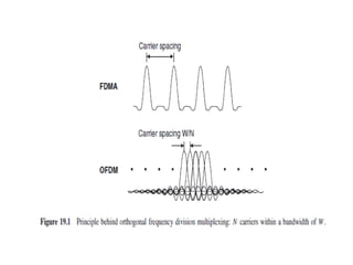
OFDM – ORTHOGONAL FREQUENCY
DIVISION MULTIPLEXING
R.Ramalakshmi
Assistant Professor
Ramco Institute of Technology
Rajapalayam
• It is a modulation scheme. It is especially suitable
for higher data rate transmission in delay
dispersive environments.
• It converts a high rate data stream into a number
of low rate streams that are transmitted over
parallel, narrowband channels that can be easily
equalized.
• OFDM is a special case of multicarrier
transmission, where a single data stream is
transmitted over a number of lower rate
subscribers.
Advantages of OFDM
• DAB – Digital Audio Broadcasting
• DVB – Digital Video Broadcasting
• Wireless LANs
• Fourth generation cellular systems, 3GPP-LTE
and WiMAX.
Principles of OFDM
• OFDM splits the information into N parallel
streams which are then transmitted by
modulating N distinct carriers called sub-carriers
or tones.
• Symbol duration Ts on each subcarrier thus
becomes larger by a factor of N.
• To separate signals carried by different
subcarriers by the receiver, they have to be
orthogonal.
• In FDMA, large frequency spacing between
carriers is used. Precious spectrum are wasted
by the carriers.
• In OFDM, a narrower spacing of subcarriers
can be achieved. The subcarriers frequencies
is given by,
fn = nW/N
• Where, n-integer
N-Different carriers
W-Total available bandwidth = N/Ts
• The modulation scheme on each of the
subcarriers is PAM – Pulse Amplitude Modulation
with rectangular basis pulses, and then the
subcarriers are mutually orthogonal,
• In time domain, due to rectangular shape of
pulses, the spectrum of each modulated carrier
has a sin(x)/x shape.
• The spectra of different modulated carriers overlap,
but each carrier is in the spectral nulls of all other
carriers.
• Therefore, the receiver does the appropriate
demodulation and integrating over symbol duration,
the data streams of any two subcarriers will not
interfere.
Implementation of Transceivers
• OFDM can be implemented in two ways,
(i) Analog Interpretation
(ii) Digital Interpretation
Transceiver structures for OFDM in
purely analogy technology
• Original data stream is first split into N parallel data
streams by S/P conversion, each of which has a lower
data rate.
• Then we have a number of local oscillators. It oscillates
at a frequency, fn = nW/N
• Each of the parallel data streams then modulates one
of the carrier.
• Actual implementation hardware effort of multiple
local oscillators is too high.
• Let the complex transmit symbol at time
instant i on the nth carrier be Cni , the transmit
signal is then,
• gn(t) – basis pulse, Cni – nth carrier, TS – symbol
period
• The transmitter can be realized by performing an IDFT on the
block of transmit symbols.
• Data source is connected with the serial to parallel converter.
• It is connected with the transmitter section.
• Its output is connected with the channel.
• The other end of the channel is connected with the receiver
section.
• The outputs from various receivers are given to the P/S block.
• The output of the P/S block is connected with the data sink.
This is the final output.
Transceiver structures for OFDM in
digital technology
• The received signal is demodulated by using
locally generated subcarriers.
• Then each signal is serially converted by P/S
conversion. The result is an estimate of the
original data Cn.
• Digital interpretation method - the data
streams are divided into blocks of N symbols.
• The block of N data symbols are subjected to an IFFT and
then transmitted.
• The input of IFFT is made up of N samples and therefore
the output from the IFFT also consists of N values.
• These N temporal sample values to be transmitted using
parallel to serial converter, one after the other.
• We can reverse the process the received is to parallel
signal is converted to serial using S/P.
• Then perform FFT on this vector, this resulted signal is an
estimate of original data Cn.
Advantages of Digital Interpretation
• It is much simpler
• Highly efficient structures exist for the
implementation of an FFT so called butterfly
structures.
REFERENCES
• 1. Rappaport,T.S., “Wireless communications”,
Second Edition, Pearson Education, 2010.
• 2. Andreas.F. Molisch, “Wireless
Communications”, John Wiley – India, 2006.
Thank You

Ofdm

  • 1.
    OFDM – ORTHOGONALFREQUENCY DIVISION MULTIPLEXING R.Ramalakshmi Assistant Professor Ramco Institute of Technology Rajapalayam
  • 2.
    • It isa modulation scheme. It is especially suitable for higher data rate transmission in delay dispersive environments. • It converts a high rate data stream into a number of low rate streams that are transmitted over parallel, narrowband channels that can be easily equalized. • OFDM is a special case of multicarrier transmission, where a single data stream is transmitted over a number of lower rate subscribers.
  • 3.
    Advantages of OFDM •DAB – Digital Audio Broadcasting • DVB – Digital Video Broadcasting • Wireless LANs • Fourth generation cellular systems, 3GPP-LTE and WiMAX.
  • 4.
    Principles of OFDM •OFDM splits the information into N parallel streams which are then transmitted by modulating N distinct carriers called sub-carriers or tones. • Symbol duration Ts on each subcarrier thus becomes larger by a factor of N. • To separate signals carried by different subcarriers by the receiver, they have to be orthogonal.
  • 5.
    • In FDMA,large frequency spacing between carriers is used. Precious spectrum are wasted by the carriers. • In OFDM, a narrower spacing of subcarriers can be achieved. The subcarriers frequencies is given by, fn = nW/N • Where, n-integer N-Different carriers W-Total available bandwidth = N/Ts
  • 7.
    • The modulationscheme on each of the subcarriers is PAM – Pulse Amplitude Modulation with rectangular basis pulses, and then the subcarriers are mutually orthogonal, • In time domain, due to rectangular shape of pulses, the spectrum of each modulated carrier has a sin(x)/x shape.
  • 8.
    • The spectraof different modulated carriers overlap, but each carrier is in the spectral nulls of all other carriers. • Therefore, the receiver does the appropriate demodulation and integrating over symbol duration, the data streams of any two subcarriers will not interfere.
  • 9.
    Implementation of Transceivers •OFDM can be implemented in two ways, (i) Analog Interpretation (ii) Digital Interpretation
  • 11.
    Transceiver structures forOFDM in purely analogy technology • Original data stream is first split into N parallel data streams by S/P conversion, each of which has a lower data rate. • Then we have a number of local oscillators. It oscillates at a frequency, fn = nW/N • Each of the parallel data streams then modulates one of the carrier. • Actual implementation hardware effort of multiple local oscillators is too high.
  • 12.
    • Let thecomplex transmit symbol at time instant i on the nth carrier be Cni , the transmit signal is then, • gn(t) – basis pulse, Cni – nth carrier, TS – symbol period
  • 13.
    • The transmittercan be realized by performing an IDFT on the block of transmit symbols. • Data source is connected with the serial to parallel converter. • It is connected with the transmitter section. • Its output is connected with the channel. • The other end of the channel is connected with the receiver section. • The outputs from various receivers are given to the P/S block. • The output of the P/S block is connected with the data sink. This is the final output.
  • 14.
    Transceiver structures forOFDM in digital technology • The received signal is demodulated by using locally generated subcarriers. • Then each signal is serially converted by P/S conversion. The result is an estimate of the original data Cn. • Digital interpretation method - the data streams are divided into blocks of N symbols.
  • 15.
    • The blockof N data symbols are subjected to an IFFT and then transmitted. • The input of IFFT is made up of N samples and therefore the output from the IFFT also consists of N values. • These N temporal sample values to be transmitted using parallel to serial converter, one after the other. • We can reverse the process the received is to parallel signal is converted to serial using S/P. • Then perform FFT on this vector, this resulted signal is an estimate of original data Cn.
  • 16.
    Advantages of DigitalInterpretation • It is much simpler • Highly efficient structures exist for the implementation of an FFT so called butterfly structures.
  • 17.
    REFERENCES • 1. Rappaport,T.S.,“Wireless communications”, Second Edition, Pearson Education, 2010. • 2. Andreas.F. Molisch, “Wireless Communications”, John Wiley – India, 2006.
  • 18.