Download to read offline
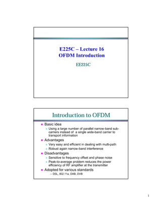
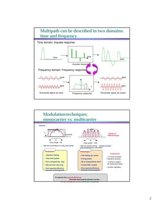
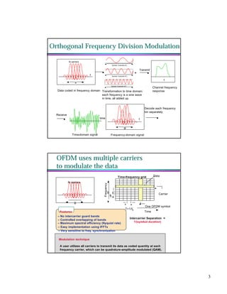
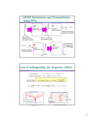


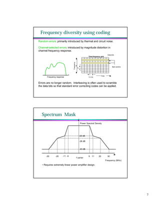
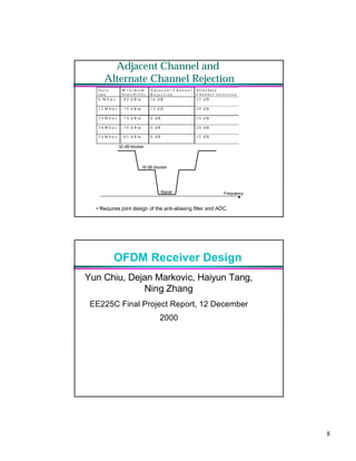
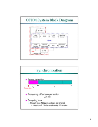


This document discusses OFDM (Orthogonal Frequency Division Multiplexing) and its use in wireless communication standards. It begins by introducing OFDM and describing its advantages like robustness to multipath interference and ability to use frequency diversity. It then covers key OFDM concepts like modulation, cyclic prefix, and synchronization using preambles. The document provides block diagrams of an OFDM transceiver and details performance metrics for synchronization and channel estimation algorithms. In summary, it provides an overview of OFDM technology fundamentals and transceiver design considerations for wireless applications.
![Multiband Transceivers - [Chapter 3] Basic Concept of Comm. Systems](https://cdn.slidesharecdn.com/ss_thumbnails/ch3-150613070933-lva1-app6892-thumbnail.jpg?width=640&height=640&fit=bounds)


![Multiband Transceivers - [Chapter 5] Software-Defined Radios](https://cdn.slidesharecdn.com/ss_thumbnails/ch5-150613070934-lva1-app6892-thumbnail.jpg?width=640&height=640&fit=bounds)