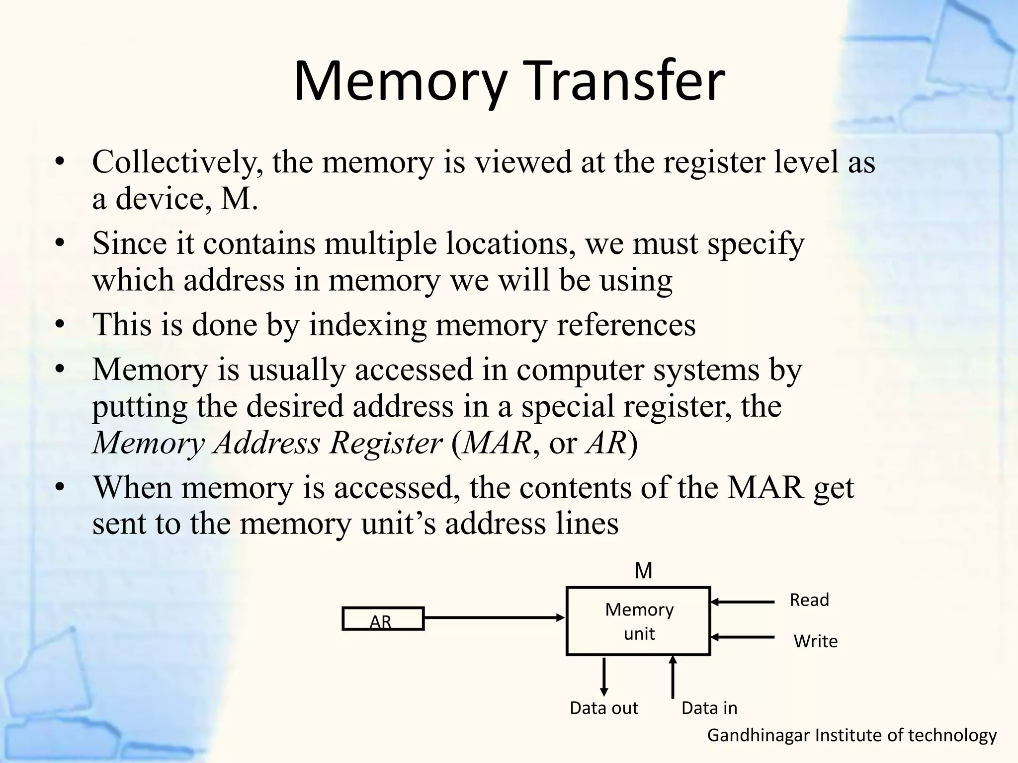
1) The document discusses different types of micro-operations including arithmetic, logic, shift, and register transfer micro-operations.
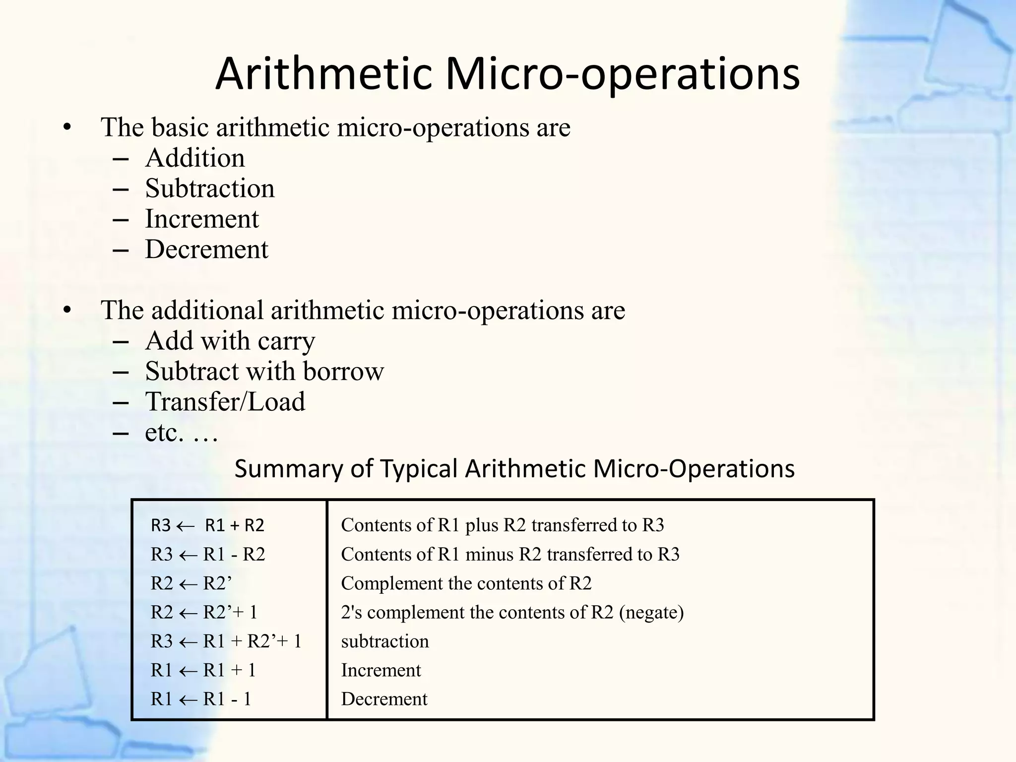
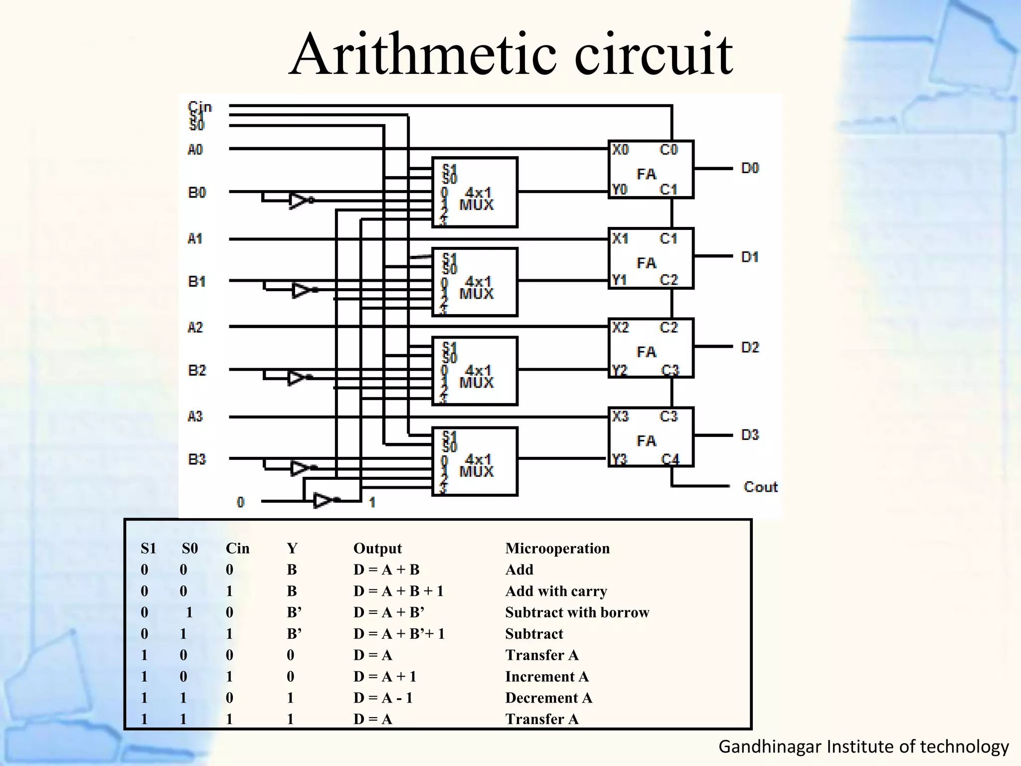
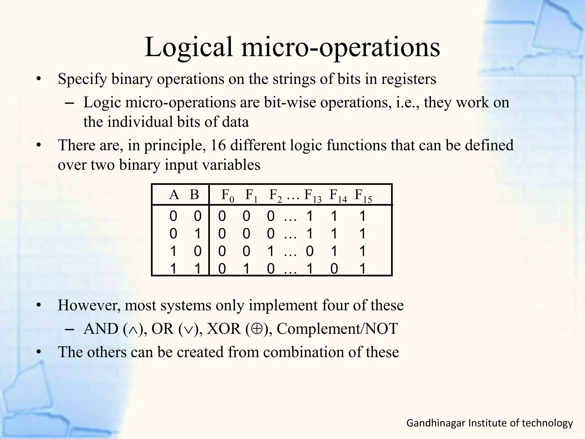
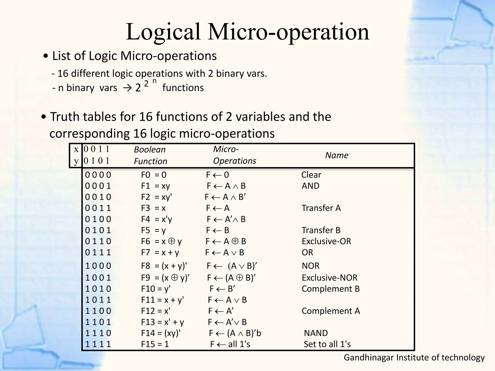
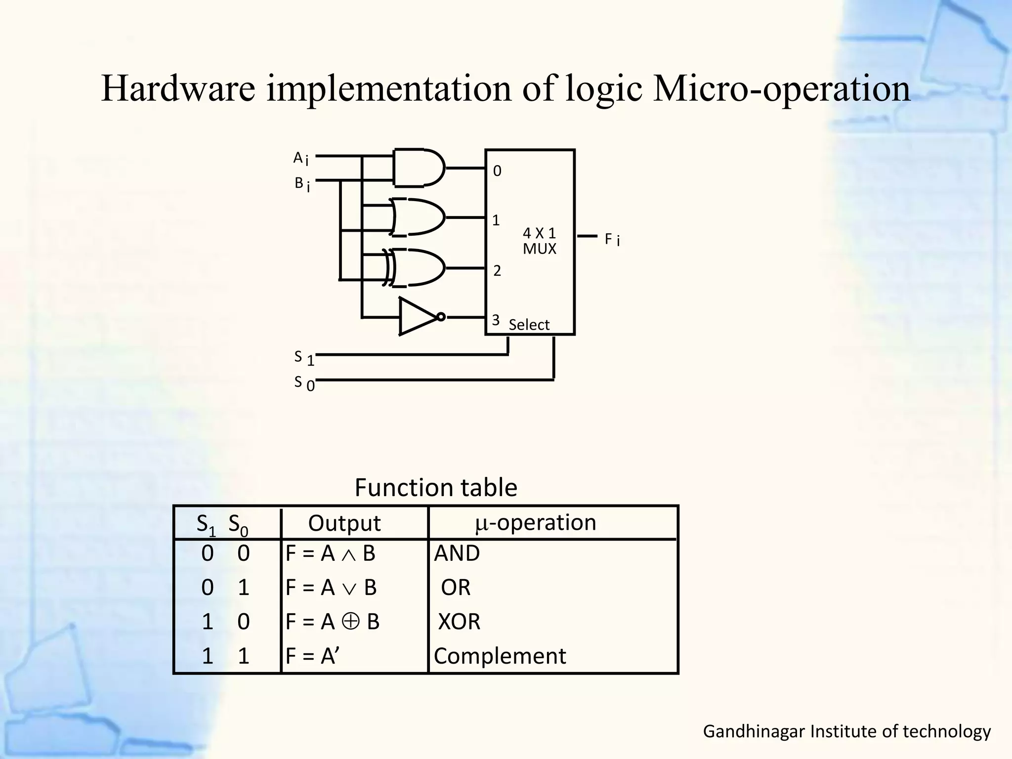
2) It provides examples of common arithmetic operations like addition, subtraction, increment, and decrement. It also describes logic operations like AND, OR, XOR, and complement.
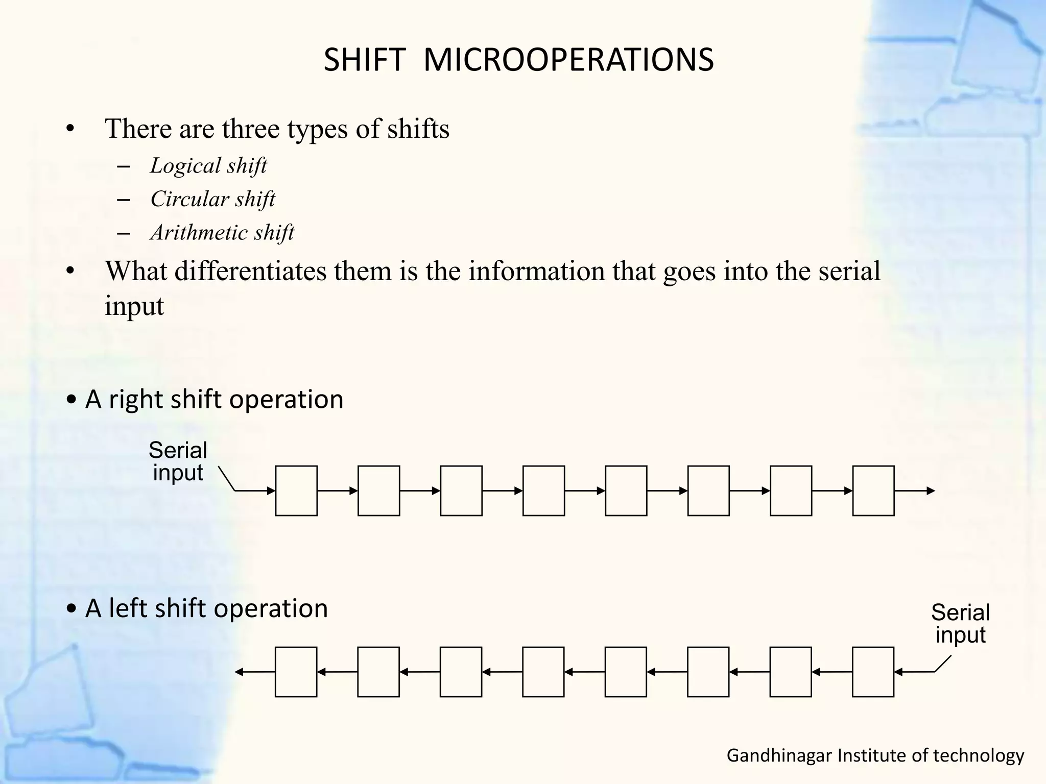
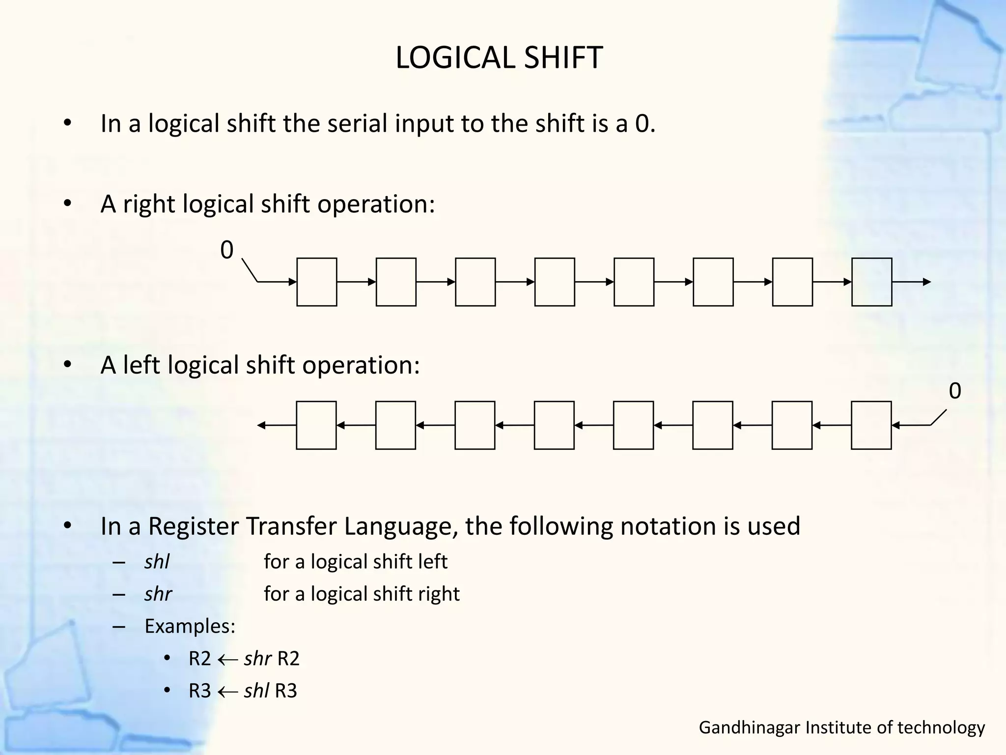
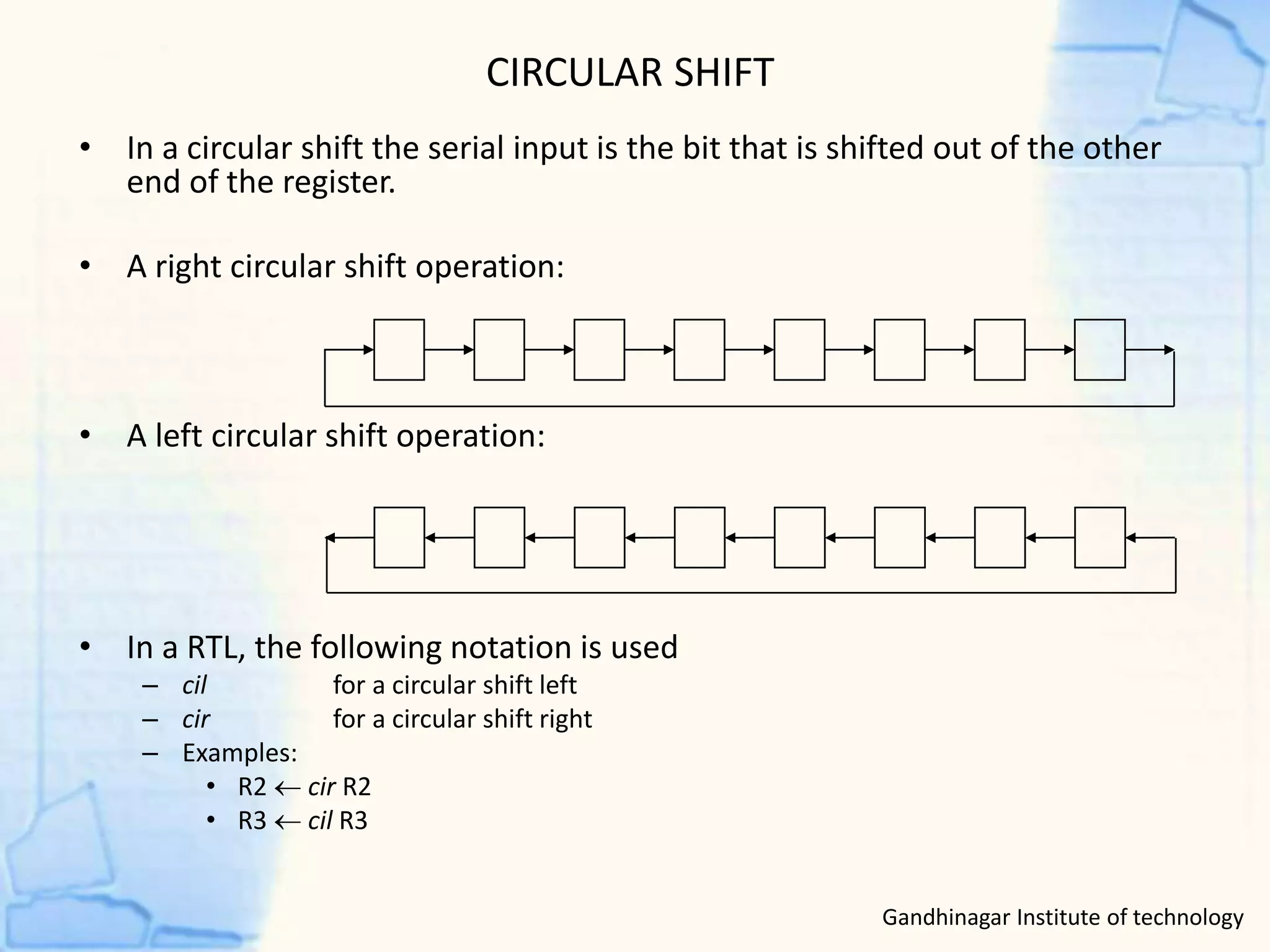
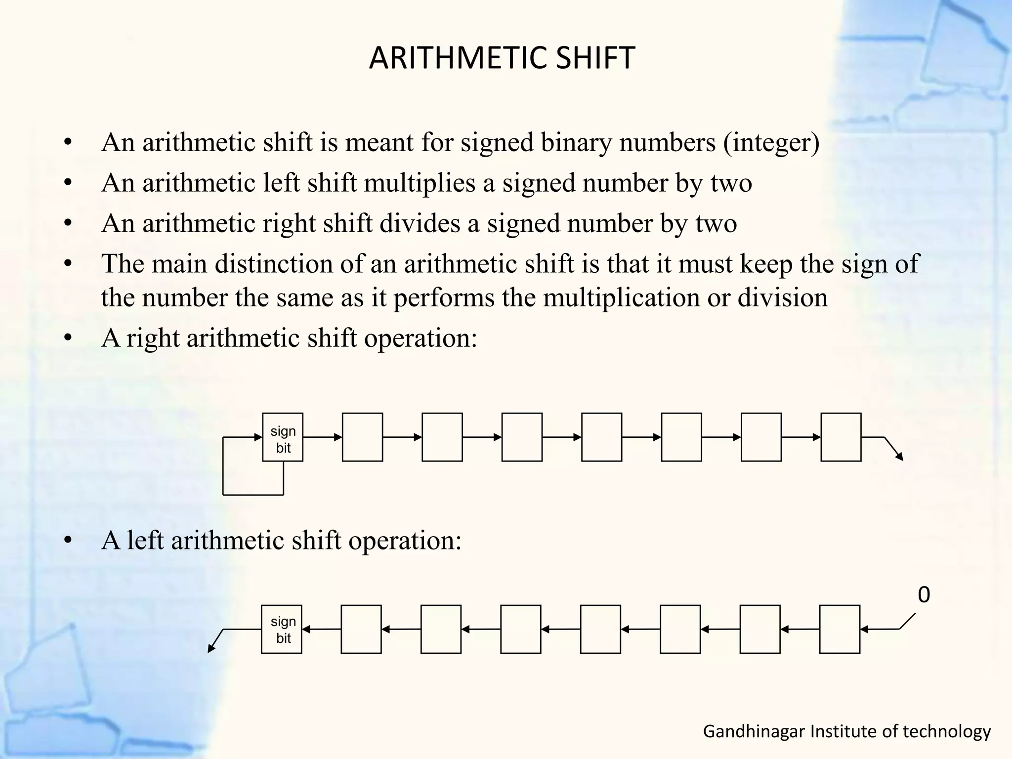
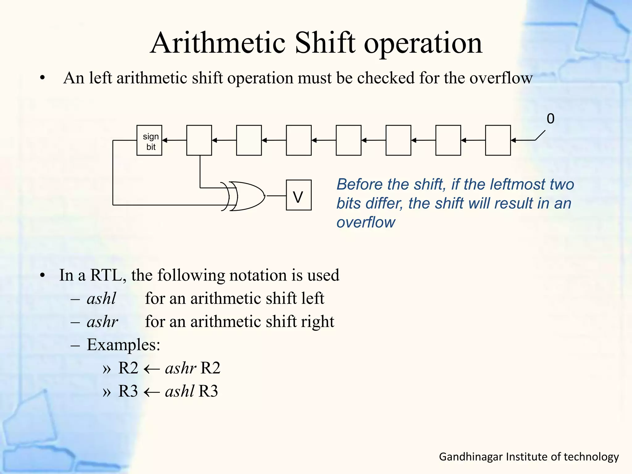
3) Shift micro-operations include logical shifts, circular shifts, and arithmetic shifts which affect the serial input differently.