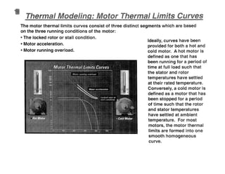
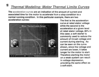
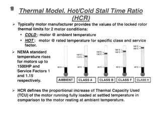
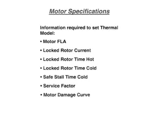
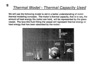
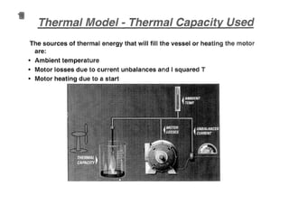
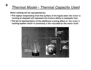
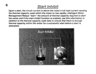
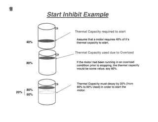
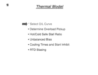
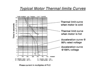
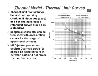
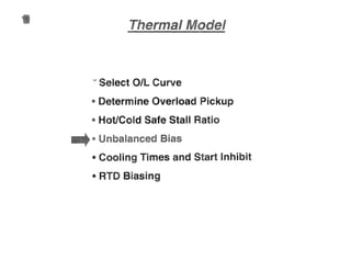
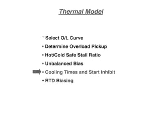
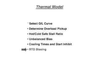
This document provides an overview of motor protection and thermal modeling concepts. It discusses how motor protection relays use thermal modeling to prevent motor failure due to overheating. The thermal model represents the motor's ability to dissipate heat and monitors the motor's thermal capacity used. It aims to limit thermal stress and protect all motor components by allowing only safe operating currents and times based on the motor's thermal limits. Settings involve determining key parameters like overload pickup, stall time ratios, cooling times and start inhibit functions.
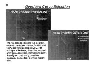


![Amit[1]](https://cdn.slidesharecdn.com/ss_thumbnails/amit1-151213064608-thumbnail.jpg?width=640&height=640&fit=bounds)


