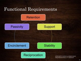
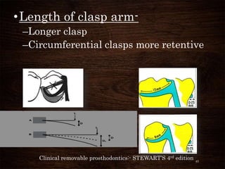
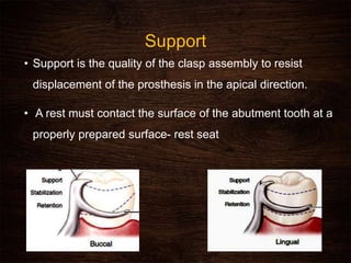
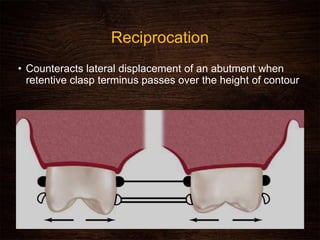
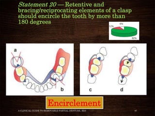
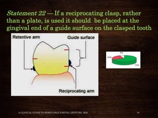
2. About the article...
⢠BRITISH DENTAL JOURNAL,
VOLUME 190, NO. 2, JANUARY 27
2001
⢠In this article statements related
to the design of clasps are listed
and discussed.
⢠The opinion of prosthodontic
experts regarding these
statements is indicated in the
accompanying pie charts.
⢠36 statements 2
3. CONTENTS
⢠Introduction
⢠What are clasps
⢠Classification
⢠Types of clasps
⢠Ideal Requirements
⢠Review of literature- discussion
⢠RPI concept
⢠Conclusion
⢠References
A CLINICAL GUIDE TO REMOVABLE PARTIAL DENTURE, BDJ 3
4. Introduction
â˘Direct retainers
â˘Intracoronal and extra coronal
DR
â˘Extra-coronal attachments &
retentive clasp assembly
â˘Clasp assembly 1899 Dr. WGA
Bonwill
A CLINICAL GUIDE TO REMOVABLE PARTIAL DENTURE, BDJ 4
5. ⢠Clasp arm- limited flexibility
⢠Passes over the greatest diameter
⢠Path of insertion and height of contour
STEWARTââS CLINICAL REMOVABLE PARTIAL PROSTHODONTICS 4TH EDITION 5
â˘Unstrained or
passive state
â˘Surveying !!!
6. ⢠Prothero cone theory 1916
⢠Height of contour- Dr Edward
Kennedy 1928
A CLINICAL GUIDE TO REMOVABLE PARTIAL DENTURE, BDJ 6
7. â˘Resistance to displacement is
encountered because the clasp arm
must undergo âdeflectionâ or
âbendingâ to pass over the height of
contour
⢠MM DeVan - Infra-bulge & Supra-bulge
A CLINICAL GUIDE TO REMOVABLE PARTIAL DENTURE, BDJ 7
8. What is a clasp (GPT 9)
It is the component of the clasp assembly
that engages a portion of the tooth
surface and either enters an undercut for
retention or remains entirely above the
height of contour to act as a
reciprocating element; generally it is
used to stabilize and retain a removable partial
denture
A CLINICAL GUIDE TO REMOVABLE PARTIAL DENTURE, BDJ 8
9. Classification of clasps
Occlusally approaching
which approach the
undercut from the
occlusal area
A CLINICAL GUIDE TO REMOVABLE PARTIAL DENTURE, BDJ 9
Gingivally approaching
which enter the
undercut crossing the
gingival margin.
10. Classification of Clasps
Supra-bulge clasps (occlusally
approaching, circumferential
clasps, Akerâs)
Infra-bulge clasps (gingivally
approaching, projection or bar
clasps, Roach clasp)
Combination clasps
A CLINICAL GUIDE TO REMOVABLE PARTIAL DENTURE, BDJ 10
11. Clasp assembly
The part of a removable dental prosthesis that acts
as a direct retainer and/or stabilizer for a
prosthesis by partially encompassing or
contacting an abutment tooth.
Components of the clasp assembly include the
clasp, the reciprocal element, the occlusal rest,
and the minor connector.
A CLINICAL GUIDE TO REMOVABLE PARTIAL DENTURE, BDJ 11
12. Parts of clasp assembly
Circumferential
Clasp
(Retentive Arm)
Reciprocating
(Bracing) Arm
Distal
Occlusal
Rest Seat Proximal
Plate
13. Rest
It is the part of the clasp that lies on the
occlusal, lingual or incisal surface of a
tooth and resist (tissue ward) movement
of the clasp by ensuring that the
retentive terminals of the clasp remain
fixed in the desired or planned depth of
undercut
Clinical removable prosthodontics:-
STEWARTâS 4rd edition
13
14. Body of the clasp
⢠It is the part of the clasp that connects
the rest and shoulder of the clasp to the
minor connector.
⢠It must be rigid.
⢠Above the height of contour.
⢠It contacts the guide plane
during insertion and removal. 14
15. Shoulder
⢠Connects the body to the clasp terminals.
⢠The shoulder must lie above the height of
contour and provide some stabilization
against horizontal displacement of the
prosthesis.
Clinical removable prosthodontics:-
STEWARTâS 4rd edition
15
16. Retentive terminal
â˘terminal end of the retentive clasp
arm.
â˘lies on the tooth surface cervical to
the height of the contour.
â˘It possesses flexibility
⢠offers the property of direct
retention.
16
17. Reciprocal Arm
â˘A rigid clasp arm
â˘above the height of contour
â˘opposing the retentive clasp arm.
â˘Resists the lateral forces exerted by retentive
terminal
Clinical removable prosthodontics:-
STEWARTâS 4rd edition
17
18. Minor Connector
â˘Joins the body to remaining part of the
framework
â˘In the gingivally approaching clasp it is
called â approach armâ.
18
19. Circumferential clasps
The cast circumferential clasp design was
introduced by Dr N B Nesbitt in 1916.
Simple, easy to construct, excellent support,
bracing, retentive properties.
Close adaptation to tooth therefore minimises
food entrapment
Disadvantage- covers large amount of tooth
surface
20. ⢠Circlet clasp.
⢠Reverse circlet
⢠Multiple circlet clasp
⢠Embrasure clasp.
⢠Reverse action or hair pin clasp
⢠Ring clasp.
⢠Back action and reverse back action clasp
22. Simple Circlet clasp
⢠Tooth support RPD
⢠Clasp projecting away from the
edentulous area
⢠Half round
⢠Disadvantages
- Increase tooth coverage
- compromised esthetics
23. Reverse circlet clasp
⢠Undercut located adjacent to edentulous area
⢠Kennedy class I ,II
⢠Disadvantages:
- Lack of rest adjacent to
edentulous area
- strength of clasp assembly
- Poor esthetics
24. Multiple circlet design
⢠2 simple circlet clasp joined at the terminal
aspect of their reciprocal elements
⢠Principle abutment is periodontally compromised
and the forces are distributed between multiple
abutment teeth
25. Embrasure clasp
⢠2 simple circlet joined at bodies
⢠Used on side of the arch where
there is no edentulous space
⢠Can be used only when
adequate tooth preparation is
possible
26. C-clasp design
⢠Fish hookâ or âHairpinâ clasp
⢠Simple circlet clasp with loop back retentive arm
⢠Sufficient crown height
⢠Disadvantages
- Insufficient flexibility
- Tooth coverage
- Esthetics compromised
27. A CLINICAL GUIDE TO REMOVABLE PARTIAL DENTURE, BDJ 27
When it is indicated ??
28. Ring clasp
⢠Indicated on a tipped mandibular molar
⢠Mesio-lingual line angle- undercut
⢠Auxiliary bracing arm
⢠Additional rest â disto-occlusally
STEWARTS REMOVABLE PARTIAL PROSTHODONTICS 4TH EDITION
28
29. ⢠Indicated on a tipped mandibular molar
Auxiliary bracing arm for additional
support , projects from minor connector
29
30. ⢠Consists of rest that covers the
entire occlusal surface and
serves as the origin for buccal
and lingual clasp arms
Onlay clasp:-
Clinical removable prosthodontics:- STEWARTâS 4rd
30
31. Combination clasp
⢠Cast metal reciprocal arm and wrought wire retentive arm
⢠abutment adjacent to Kennedy class I and II area
Advantage
⢠can engage greater undercut
Disadvantage
⢠more prone to breakage than cast
⢠minimal stabilizing
33. Approach arm
⢠It is a minor connector that connect the retentive
tip to the denture base.
⢠It crosses the gingival margin at right angle and
it is the only flexible minor connector.
⢠Flexibility of the clasp is controlled by the taper
and length of the approach arm
⢠More esthetic
36. ⢠Approach arm extends till
height of contour at which the
retentive terminal leaves the
approach arm and engages
an undercut
⢠It is contraindicated if height
of contour is located near
occlusal surface & Severe
soft tissue undercut
⢠Esthetically superior
T clasp
36
37. ⢠T-clasp without the non retentive finger of
the T-terminal
⢠Has better esthetics and used in canines
and premolars
Modified T-clasp
37
38. ⢠It is used when the height of
contour on the buccal surface of
abutment is high near the mesial
and distal line angles, but low at
the centre
Y-clasp
Clinical removable prosthodontics:- STEWARTâS 4rd editio
38
39. I bar
⢠Kennedy class I and II
⢠RPI
- Mesial rest
- Proximal plate
- I bar
⢠Used on distobuccal surface of
maxillary canines
41. Retention
â˘âRetention is the inherent quality of the
clasp assembly that resists forces acting
to dislodge components away from the
supporting tissuesâ.
⢠No single component of a clasp assembly is
solely responsible for prosthesis retention.
⢠Rather, it is effective design and accurate
construction that make the removable partial
denture retentive.
Clinical removable prosthodontics:- STEWARTâS 4rd
edition
41
42. ⢠The amount of retention designed into a
removable partial denture should always be
the minimum necessary to resist reasonable
dislodging forces.
⢠A rigid clasp flexing over the height of contour
may transfer harmful stresses to an abutment
during insertion, removal, and functional
movement of the prosthesis.
⢠An only a minimum area of contact should be
seen.
42
43. Factors affecting Retention
ďź Type of clasp
ďź Flexibility of the retentive arm
ďź Axial convergence of tooth surface apical to
the height of contour. ( depth of undercut
engaged)
ďź Angle of Approach of the clasp arm .
43
(PARTIAL DENTURE, Osborne &
Lammie 4th edition)
44. Flexibility influenced by :
⢠length,
⢠cross sectional form,
⢠cross sectional diameter,
⢠longitudinal taper,
⢠clasp curvature,
⢠metallurgical characteristics of the
alloy.
A CLINICAL GUIDE TO REMOVABLE PARTIAL DENTURE, BDJ 44
45. â˘Length of clasp arm-
âLonger clasp
âCircumferential clasps more retentive
Clinical removable prosthodontics:- STEWARTâS 4rd edition 45
46. ⢠Longitudinal taper
âThe clasp arm should taper from the
point of origin to provide its flexibility.
Clinical removable prosthodontics:- STEWARTâS 4rd edition
46
47. â˘Diameter of the clasp:
Clinical removable prosthodontics:- STEWARTâS 4rd
edition 47
49. Support
⢠Support is the quality of the clasp assembly to resist
displacement of the prosthesis in the apical direction.
⢠A rest must contact the surface of the abutment tooth at a
properly prepared surface- rest seat
50. ⢠A properly prepared rest will prevent the tissue
ward movement of the prosthesis.
⢠maintains the position of the clasp assembly in
relation to the abutment.
⢠Transmits forces along the long axis of the
abutments
56. Review of the Article
A CLINICAL GUIDE TO REMOVABLE PARTIAL DENTURE, BDJ 56
⢠Statement 1 â A clasp should always be
supported by a rest
57. ⢠The retentive tip of the clasp will lose contact
with the tooth. It will not therefore provide
retention for the denture until there has been
sufficient movement of the denture in an
occlusal direction to re-establish contact of
the clasp with the tooth. The denture may
therefore seem loose to the patient.
⢠The tip of the clasp may sink into and
damage the gingiva
A CLINICAL GUIDE TO REMOVABLE PARTIAL DENTURE, BDJ 57
58. ⢠This statement is not universally
applicable.
⢠For example, acrylic mucosally
supported RPDs often employ wrought
wire clasps without tooth support.
However, even in this situation tooth
support for clasps can sometimes
usefully be obtained by wrought wire
rests or clasp arms extending onto the
occlusal surfaces.
A CLINICAL GUIDE TO REMOVABLE PARTIAL DENTURE, BDJ 58
59. ďśIt might be preferable to omit tooth support
when there are very few teeth remaining and
rests on them would produce a support axis that
approximately bisects the denture. In this
situation tooth support can contribute to
instability of an RPD because the denture tends
to rock about the support axis.
A CLINICAL GUIDE TO REMOVABLE PARTIAL DENTURE, BDJ
59
60. ⢠If however, there are very few teeth remaining,
but rests on them would produce a
⢠support axis which forms a tangent to the
residual ridge, tooth support can usually be
⢠employed to advantage and the denture remain
acceptably stable
A CLINICAL GUIDE TO REMOVABLE PARTIAL DENTURE, BDJ 60
61. Statement 2 â A molar ring clasp should
have occlusal rests mesially and
distally
A CLINICAL GUIDE TO REMOVABLE PARTIAL DENTURE, BDJ 61
62. ⢠Contribute to more axial loading of a tilted
abutment tooth This will reduce the leverage
on the tooth compared with a mesial rest used
alone.
⢠Support the clasp arm on the tooth distally so
that if the clasp arm is inadvertently bent it is
unlikely that the arm can move far enough
gingivally to traumatise the periodontal
tissues
A CLINICAL GUIDE TO REMOVABLE PARTIAL DENTURE, BDJ 62
63. Why the prosthodontic specialists do not
favour this arrangement?
The commonest method of supporting a
ring clasp is with an occlusal rest
adjacent to the saddle.
Occasionally clinical circumstances may
dictate that a non-adjacent rest be used.
This results in the entire load from the
saddle to the rest being transmitted
along the proximal section of the clasp. It
is necessary therefore to strengthen this
section, for example by thickening it.
A CLINICAL GUIDE TO REMOVABLE PARTIAL DENTURE, BDJ 63
64. Statement 3 â A molar ring clasp, which
engages lingual undercut, should
have a buccal strengthening arm.
A CLINICAL GUIDE TO REMOVABLE PARTIAL DENTURE, BDJ 64
65. Statement 4 â Retentive clasps can be used to
provide indirect support for a distal extension
saddle by being placed on the opposite side of the
support axis from the saddle
A CLINICAL GUIDE TO REMOVABLE PARTIAL DENTURE, BDJ 65
66. ⢠displaceability of the supporting mucosa
allows the saddle to sink.
⢠denture rotates about the âsupport axisâ
⢠denture components anterior to the
support axis move in an occlusal
direction
⢠clasp placed on the other side of the
support axis from the distal extension
saddle will tend to resist this movement
to a limited extent
A CLINICAL GUIDE TO REMOVABLE PARTIAL DENTURE, BDJ 66
67. ⢠occlusal loads tend to be high and
the retentive force generated by
the clasp relatively low
⢠the occlusal loads are usually
working at a mechanical
advantage to the clasp.
⢠This arrangement is therefore
ineffective.
A CLINICAL GUIDE TO REMOVABLE PARTIAL DENTURE, BDJ 67
68. ⢠Rather than trying to obtain indirect
support for a distal extension saddle it
is normally advisable to focus on:
Optimising direct support of the saddle
through:
⢠full extension of the base
⢠the altered cast technique
⢠the use of mesial occlusal rests
⢠regular maintenance, including
relining when necessary
A CLINICAL GUIDE TO REMOVABLE PARTIAL DENTURE, BDJ 68
69. Statement 5 â A wrought wire clasp
should be attached to a saddle, not to
exposed parts of the metal framework
A CLINICAL GUIDE TO REMOVABLE PARTIAL DENTURE, BDJ 69
70. Statement 6 â An occlusally-approaching clasp,
which is supported by an rest, should not
approach closer than 1 mm to the gingival
margin
A CLINICAL GUIDE TO REMOVABLE PARTIAL DENTURE, BDJ 70
⢠clasp is closer than 1 mm to the gingival
margin âgingival irritation.
⢠clasp is not supported by a rest-- the
separation of clasp tip and gingival
margin should be greater than 1 mm
71. Statement 7 â A retentive occlusally-approaching
clasp should run from the side of the tooth with
the least undercut to the side with the greatest
undercut
A CLINICAL GUIDE TO REMOVABLE PARTIAL DENTURE, BDJ 71
72. ⢠Most effective utilization of available
undercut
⢠Optimum positioning of the clasp arm on
the tooth.
A CLINICAL GUIDE TO REMOVABLE PARTIAL DENTURE, BDJ 72
73. Statement 8 â Occlusally-approaching retentive
clasps should have the terminal third of the
retentive arm entering the undercut
⢠If the clasp arm crosses the survey line
prematurely, the arm is likely to permanently
deform in function and to apply excessive force to
the tooth. It is also likely to make insertion and
removal of the denture difficult or impossible
A CLINICAL GUIDE TO REMOVABLE PARTIAL DENTURE, BDJ 73
74. Statement 9 â A retentive occlusally-
approaching clasp should engage
0.25 mm of undercut if it is constructed in
cast cobalt chromium alloy
A CLINICAL GUIDE TO REMOVABLE PARTIAL DENTURE, BDJ 74
75. Statement 10 â If an undercut on a tooth, which
needs to be clasped for retention, is less than 0.25
mm, then composite resin should be added to the
tooth to create at least this amount of undercut
A CLINICAL GUIDE TO REMOVABLE PARTIAL DENTURE, BDJ 75
76. ďśOther ways of creating undercuts for
clasp retention are:
⢠Enameloplasty, by using a bur to create
a small dimple in the enamel which can
be engaged by the tip of a clasp
⢠Metal or porcelain veneers bonded to the
enamel surface.
⢠The fitting of suitably contoured crowns.
A CLINICAL GUIDE TO REMOVABLE PARTIAL DENTURE, BDJ 76
77. Statement 11 â A retentive clasp should
be at least 15 mm in length if it is
constructed in cast cobalt chromium alloy
⢠For the retentive tip of a cobalt
chromium clasp to flex 0.25 mm without
deforming permanently, it needs to be
about 15 mm in length
⢠This length can usually be achieved with
an occlusally-approaching clasp on a
molar tooth, and a gingivally-
approaching clasp on any tooth.
A CLINICAL GUIDE TO REMOVABLE PARTIAL DENTURE, BDJ 77
78. Statement 12 â Occlusally-approaching
retentive clasps should be restricted to molar
teeth if constructed in cast cobalt chromium
alloy
⢠A gingivally-approaching clasp can be
made longer than 15 mm and in such
cases the clasp can engage a depth of
undercut greater than 0.25 mm.
A CLINICAL GUIDE TO REMOVABLE PARTIAL DENTURE, BDJ 78
79. Statement 13 â A retentive clasp should
engage 0.5 mm of undercut if it is
constructed in wrought wire
A CLINICAL GUIDE TO REMOVABLE PARTIAL DENTURE, BDJ 79
â˘needs to engage a greater depth of undercut to
generate equivalent retention.
⢠As a wrought wire clasp has a higher
proportional limit than a cast clasp it can engage
this increased undercut without deforming
permanently.
80. ⢠There can be technical difficulties in the
production of accurately fitting wrought
wire clasps as the required skill is not
universally available
A CLINICAL GUIDE TO REMOVABLE PARTIAL DENTURE, BDJ 80
81. Statement 14 â A retentive clasp should
be at least 7 mm in length if it is
constructed in wrought wire
⢠A wrought clasp of about 7 mm in length can
engage 0.5 mm of undercut without deforming
permanently.
⢠However, if the wrought clasp is shorter that 7
mm, flexing into this undercut is likely to result
in permanent deformation.
A CLINICAL GUIDE TO REMOVABLE PARTIAL DENTURE, BDJ 81
82. Statement 15 â If an occlusally-
approaching retentive clasp is used on a
premolar or canine it should be
constructed in wrought wire
⢠A premolar or canine tooth is usually wide
enough mesio-distally to accept an occlusally-
approaching clasp of about 7 mm in length but
not much longer.
⢠A wrought clasp can therefore provide reliable
retention in this situation whereas a cast clasp
would be too rigid.
A CLINICAL GUIDE TO REMOVABLE PARTIAL DENTURE, BDJ 82
83. Statement 16 â Retentive clasps should
usually be placed buccally on upper
teeth
⢠Retentive clasps should obviously only
be placed where suitable undercuts exist
or can be created.
⢠In the molar region this distribution of
undercuts is associated with the tilt of
the teeth
A CLINICAL GUIDE TO REMOVABLE PARTIAL DENTURE, BDJ 83
84. Statement 17 â Retentive clasps should
usually be placed lingually on lower
molar teeth
⢠Undercuts suitable for retentive clasping
of lower molar teeth are most frequently
located lingually.
A CLINICAL GUIDE TO REMOVABLE PARTIAL DENTURE, BDJ 84
85. Statement 18 â Retentive clasps should
usually be placed buccally on lower
premolar or canine teeth
⢠Undercuts suitable for retentive clasping
of lower premolar or canine teeth are
most frequently located buccally.
A CLINICAL GUIDE TO REMOVABLE PARTIAL DENTURE, BDJ 85
86. Statement 19 â Where there are clasps on
opposite sides of the arch, the retentive arms
are best placed on opposing tooth surfaces, ie
buccal/buccal or lingual/lingual
⢠This is because the retentive clasps then
move along divergent paths of
displacement.
⢠This is sometimes referred to as âcross-
arch reciprocationâ . It is not as effective
as reciprocation via guide surfaces on
the clasped teeth as relative movement
of the teeth within the periodontal
ligaments is not prevented
A CLINICAL GUIDE TO REMOVABLE PARTIAL DENTURE, BDJ 86
87. Statement 20 â Retentive and
bracing/reciprocating elements of a clasp
should encircle the tooth by more than
180 degrees
A CLINICAL GUIDE TO REMOVABLE PARTIAL DENTURE, BDJ 87
Encirclement
88. Statement 21 â Reciprocation should be
provided on a clasped tooth diametrically
opposite the retentive clasp tip
88
89. Reciprocation is resistance to:
⢠a) Displacement of a tooth by a direct retainer.
If a retentive clasp is not reciprocated, the
clasp will apply a horizontal force to a tooth as
it moves towards the height of contour of the
tooth and this will displace the tooth within the
periodontal ligament. This movement of the
tooth will reduce the retentiveness of the clasp.
⢠b) Escape of a direct retainer from an undercut.
If there is no reciprocation, the clasp will be
able to escape from the undercut without
flexing and creating a retentive force.
A CLINICAL GUIDE TO REMOVABLE PARTIAL DENTURE, BDJ 89
90. The most effective location for a reciprocating
component is:
⢠a) On the clasped tooth
⢠b) Diametrically opposite the retentive tip of the
clasp.
⢠It should be remembered that the RPI system
does not conform to (b) as effective reciprocation
is provided by the combination of mesial and
distal guide plates that are not diametrically
opposite the I-bar
90
91. Statement 22 â If a reciprocating clasp, rather
than a plate, is used it should be placed at the
gingival end of a guide surface on the clasped tooth
A CLINICAL GUIDE TO REMOVABLE PARTIAL DENTURE, BDJ 91
92. If the reciprocating clasp is placed at the
gingival end of a guide surface (which is
usually 2â3 mm in length), it will
maintain contact with that surface as
the retentive clasp moves through the
retentive distance.
Reciprocation will therefore be
maintained for as long as the retentive
clasp is active.
A CLINICAL GUIDE TO REMOVABLE PARTIAL DENTURE, BDJ 92
93. Statement 23 â Where a plate connector
is used, reciprocation can be
obtained by a guide plate on the connector
A CLINICAL GUIDE TO REMOVABLE PARTIAL DENTURE, BDJ 93
94. ⢠Where a plate major connector contacts a
clasped tooth, a guide surface can be
incorporated into it by using a surveyor
to block out undercuts on the master cast
prior to fabricating the refractory cast.
The guide surface is therefore made
parallel to the planned path of insertion
and removal of the denture . However,
reciprocation will not be provided by a
plate if the tooth surface contacted has
no undercut
A CLINICAL GUIDE TO REMOVABLE PARTIAL DENTURE, BDJ 94
95. Statement 24 â A gingivally-approaching
clasp is contraindicated if the buccal
sulcus is less than 4 mm in depth
A CLINICAL GUIDE TO REMOVABLE PARTIAL DENTURE, BDJ 95
96. ⢠A sulcus of less than 4 mm does not have
sufficient depth to accommodate a gingivally
approaching clasp without much of the length of
the clasp arm being placed too close to the
gingival margin
⢠An exception to this statement is the âDe Vanâ
clasp which is a gingivally-approaching clasp
running along the border of the saddle to engage
the disto buccal undercut of the abutment tooth.
It does not enter the sulcus area buccal to the
clasped tooth
A CLINICAL GUIDE TO REMOVABLE PARTIAL DENTURE, BDJ 96
97. Statement 25 â Gingivally-approaching clasps are
contra indicated if there is a tissue undercut
buccally on the alveolus more than 1 mm in depth
within 3 mm of the gingival margin
A CLINICAL GUIDE TO REMOVABLE PARTIAL DENTURE, BDJ 97
98. ⢠An undercut of these dimensions results in the
gingivally-approaching clasp being relieved
extensively from the attached mucosa so that
the denture can be inserted without
traumatizing the tissues.
⢠Such relief causes the arm of the clasp to be
excessively prominent,
⢠resulting in possible irritation of the buccal
mucosa, and the trapping of food debris
⢠Alternatively, if the clasp arm is placed on the
mucosa survey line it is likely
⢠to be too prominent and too close to the gingival
margin
A CLINICAL GUIDE TO REMOVABLE PARTIAL DENTURE, BDJ 98
99. Statement 26 â A gingivally-approaching
clasp should be used if a retentive
cast cobalt chromium clasp is required on a
premolar or canine tooth, assuming that
sulcus anatomy is favourable
⢠A gingivally-approaching clasp is an
appropriate choice under such circumstances as
it can be made long enough to achieve adequate
flexibility.
⢠Canine and premolar teeth obviously vary in
their mesiodistal dimension but are generally of
the order of 7 mm. A cast cobalt chromium
occlusally-approaching clasp may be a little
longer than this (allowing for the curvature of
the tooth surface and the fact that the clasp
passes diagonally across the tooth).
A CLINICAL GUIDE TO REMOVABLE PARTIAL DENTURE, BDJ 99
100. However, this may not be long enough to ensure
that such a clasp has adequate flexibility and is
working within its proportional limit.
Therefore, on such teeth, more effective and
reliable clasping can be obtained either by
utilizing the longer gingivally-approaching
clasp or by using a more flexible material
(wrought wire).
A CLINICAL GUIDE TO REMOVABLE PARTIAL DENTURE, BDJ 100
101. Statement 27 â A distal extension saddle should
have a retentive I-bar clasp
whose tip contacts the most prominent part of the
buccal surface of the
abutment tooth mesiodistally.
A CLINICAL GUIDE TO REMOVABLE PARTIAL DENTURE, BDJ 101
Minimal
tooth and
tissue
coverage with
stress control
102. ⢠In the RPI system, the tip of the
gingivally-approaching I-bar clasp
contacts the most prominent part of the
buccal surface of the abutment tooth
mesiodistally.
⢠Thus when the distal extension saddle
sinks under occlusal loads, the tip of the
clasp moves mesially out of contact with
the tooth and does not apply any
potentially damaging torque to it
A CLINICAL GUIDE TO REMOVABLE PARTIAL DENTURE, BDJ 102
103. 103
{Symposium Of Removable Partial
Dentures
RPI (Rest, Proximal Plate, I Bar) Clasp
Retainer and Its Modifications
Arthur J . Krol, D.D.S*Dental Clinics of
North America - Vol. 17, No.4, October
1973}
105. Statement 28 â The RPI system (Rest, Plate, I-
bar clasp) should be used on premolar abutment
teeth for mandibular distal extension saddles if
the tooth and buccal sulcus anatomy is favourable
A CLINICAL GUIDE TO REMOVABLE PARTIAL DENTURE, BDJ,
SYMPOSIUM OF REMOVABLE PARTIAL DEL/LURES RPI (REST, PROXIMAL PLATE, I BAR) CLASP
RETAINER AND ITS MODIFICATIONS
ARTHUR J . KROL, D.D.S* 105
106. Statement 29 â The RPI system (Rest, Plate, I-
bar clasp) should be used on
premolar abutment teeth for maxillary distal
extension saddles if the tooth
and buccal sulcus anatomy is favourable
⢠The RPI system is not such a
popular choice for the maxilla as in
the mandible, possibly
⢠because the potential for support
from the denture-bearing area is
greater in the maxilla than in the
mandible, ie the âsupport deficitâ is
less. The potential for harmful
torque forces being applied to the
abutment tooth is therefore
reduced.
A CLINICAL GUIDE TO REMOVABLE PARTIAL DENTURE, BDJ
106
107. Statement 30 â If the retentive clasp for a
distal extension saddle is on a
premolar or canine abutment, it should be
either a cast gingivally approaching
I-bar or a wrought wire occlusally-
approaching clasp.
107
These are two types of clasp that
minimize the chance of applying
damaging torque
to the abutment teeth of distal
extension saddles.
In the case of a wrought wire
occlusally-approaching clasp, the
ability of the round
section wire to flex in any direction
also assists in avoiding potentially
damaging torque.
108. Statement 31 â A distal extension saddle
should have a retentive clasp on
the abutment tooth
A CLINICAL GUIDE TO REMOVABLE PARTIAL DENTURE, BDJ 108
When practicable it is
desirable to place a
retentive clasp on the
abutment tooth adjacent
to a distal extension saddle
so that one end of the clasp
axis is located as close to
the saddle as possible
109. Statement 32 â A unilateral distal
extension saddle denture (Kennedy II)
should have one clasp as close to the
saddle as possible and the other as far
posteriorly as possible on the other side of
the arch
A CLINICAL GUIDE TO REMOVABLE PARTIAL DENTURE, BDJ 109
110. ⢠These principles:
⢠⢠Provide the most efficient direct retention for
the mesial end of the saddle.
⢠⢠Locate the clasp axis as far posteriorly as
possible so that the most effective indirect
retention can be provided for the distal
extension saddle.
A CLINICAL GUIDE TO REMOVABLE PARTIAL DENTURE, BDJ 110
111. Statement 33 â Rather than making a design
statement this section poses a question:
âWhat is the preferred number of clasps for RPDs
restoring each of the Kennedy classes of partially
dentate arch?â
A CLINICAL GUIDE TO REMOVABLE PARTIAL DENTURE, BDJ 111
112. ⢠The pie charts indicate the percentage of
prosthodontists preferring 2, 3 or 4 clasps for
each of the Kennedy classes.
⢠For all of the Kennedy classes the use of two
clasps is the most popular choice for RPD
retention. Two clasps are advantageous because:
--Simple denture designs are often better
tolerated and minimize tissue coverage.
--Two clasps usually generate sufficient
retention.
-- A pair of clasps creates a clasp axis that
can be positioned to bisect the denture and allow
indirect retention to be obtained.
A CLINICAL GUIDE TO REMOVABLE PARTIAL DENTURE, BDJ 112
113. Statement 34 â Bounded saddles should
have a clasp at least at one end
⢠This allows for the utilization of
indirect retention if required
A CLINICAL GUIDE TO REMOVABLE PARTIAL DENTURE, BDJ 113
114. Statement 35 â A Kennedy III Modification 1
denture should have two retentive clasps
forming a diagonal clasp axis which bisects the
denture
A CLINICAL GUIDE TO REMOVABLE PARTIAL DENTURE, BDJ 114
115. ⢠If one end of a bounded saddle has a retentive
clasp the other end will tend to be lifted by
displacing forces.
⢠This tilting effect can be resisted by using an
indirect retainer.
⢠If a bounded saddle has no direct retainer at
either end indirect retention cannot be used to
assist in the stabilization of the saddle.
A CLINICAL GUIDE TO REMOVABLE PARTIAL DENTURE, BDJ 115
116. Statement 36 â A Kennedy IV denture
should have retentive clasps on the first
molars if there is suitable undercut present
A CLINICAL GUIDE TO REMOVABLE PARTIAL DENTURE, BDJ 116
117. ⢠This is usually a good site for a pair of clasps
retaining a Kennedy IV denture because:
⢠aesthetically acceptable
⢠it might be better to place the clasps even further
back on the second molars if suitable sites exist.
⢠⢠The molar is a sufficiently large tooth for cast
occlusally-approaching clasps to be long enough to
achieve adequate flexibility and resistance to
permanent deformation.
⢠⢠The clasps are sufficiently posterior to the
support axis of the saddle to efficiently resist
tipping of the denture as the result of incising
forces, ie to provide indirect support for the saddle
A CLINICAL GUIDE TO REMOVABLE PARTIAL DENTURE, BDJ 117
118. ⢠⢠If the retentive tips of the clasps can be placed
mesially on the molars, the occlusal rests on the
molar teeth will provide some indirect retention
for the anterior saddle.
⢠In this instance the indirect retainers will be
relatively close to the clasp axis and therefore
their effectiveness will be limited. However,
some direct retention is already likely to have
been obtained for the anterior saddle by the
saddle contacting guide surfaces on the
abutment teeth and by the labial flange
engaging undercut on the ridge. Therefore the
modest indirect retention provided by the molar
rests may be sufficient to stabilize the RPD.
A CLINICAL GUIDE TO REMOVABLE PARTIAL DENTURE, BDJ 118
119. Conclusion
⢠Design varies from case to case
⢠selection of appropriate design is critical for a
successful treatment
A CLINICAL GUIDE TO REMOVABLE PARTIAL DENTURE, BDJ 119
120. REFERENCES :
⢠Clasp design , BRITISH DENTAL JOURNAL, VOLUME
190, NO. 2, JANUARY 27 2001
⢠A clinical guide to removable partial denture, BDJ
⢠Stewartâs clinical REMOVABLE PARTIAL
PROSTHODONTICS 4th Edition
⢠Partial dentures , John Osborne & Lammie , 4th edition
⢠RPI (Rest, Proxima1 Plate, I Bar) Clasp : Retainer and
Its Modifications, Arthur J . Krol, D.D.S, Dental Clinics
of North America - Vol. 17, No.4, October 1973
A CLINICAL GUIDE TO REMOVABLE PARTIAL DENTURE, BDJ 120