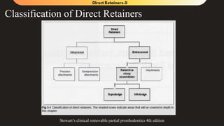
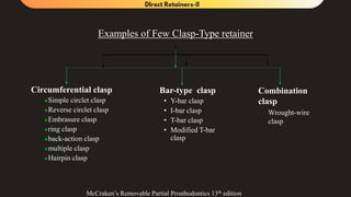
Recap…
• Suprabulge clasps
• Infrabulge clasps
• Design Philosophies utilizing I-
Bar
• Studies relevant to kinetics of
direct retainer and terminal
abutment.
• Summary
• References
Learning Objectives
Sr.no Topic Domain Significance
1. Design rules of Suprabulge
clasps
Cognitive &
Psychomotor
Must know
2. The examples of Suprabulge
clasp and their designs
Cognitive &
Psychomotor
Must know
3. Design rules of Infrabulge
Clasp
Cognitive &
Psychomotor
Must know
4. The examples of Infrabulge
clasp and their design
Cognitive &
Psychomotor
Must know
5. The Design Philosophies
utilizing I bar Claps
Cognitive &
Psychomotor
Must know
Classification of Direct Retainers
Stewart’s clinical removable partial prosthodontics 4th edition
Examples of Few Clasp-Type retainer
Bar-type clasp
• Y-bar clasp
• I-bar clasp
• T-bar clasp
• Modified T-bar
clasp
Circumferential clasp
Simple circlet clasp
Reverse circlet clasp
Embrasure clasp
ring clasp
back-action clasp
multiple clasp
Hairpin clasp
Combination
clasp
• Wrought-wire
clasp
McCraken’s Removable Partial Prosthodontics 13th edition
Design Rules for Cast Circumferential Clasp
• It originates from a portion of the framework that lies
above the height of contour
• It follows cervically in an arcing fashion
• Only the terminal part of the clasp arm crosses the
height of contour
• The reciprocal arm must be located at or slightly above
the height of contour
• The retentive terminus is directed occlusally
• Should terminate at the mesial or distal line angles of
the abutment
A Cast circumferential claps must never be given on
1. Mesio-facial undercut of terminal abutment of a distal extension RPD
2. Disto-facial undercut of abutment distal to long span anterior edentulous space
1.Simple Circlet Clasp
• Clap of Choice for Tooth Supported
Removable Partial Dentures.
• A simple circlet clasp usually
originates on the proximal surface of
an abutment adjacent to an
edentulous area, with the clasp arms
projecting away from the edentulous
space.
• The terminus of the retentive arm
engages an undercut that is remote
from the edentulous space.
Stewarts’s Clinical Removable Partial Prosthodontics 4th Edition
Limitations of Simple Circlet Clasp.
• Difficult to Adjust, only can be adjusted in bucco-lingual direction.
• Tends to increase the circumference of the clinical crown. This may interfere
with the elimination of food from the occlusal table and may deprive the
adjacent gingival tissues of essential physiologic stimulation.
• Increased tooth coverage may promote decalcification and compromise dental
aesthetics.
Stewarts’s Clinical Removable Partial Prosthodontics 4th Edition
2. Reverse Circlet Clasp
• Used when the available undercut is located at the facial or lingual line angle
adjacent to an edentulous space.
• Infrabulge clasp is preffered more than this clasp.
• Clasp of choice in Kennedy’s Class I and Class II edentulous cases.
Stewarts’s Clinical Removable Partial Prosthodontics 4th Edition
Limitations of Reverse Circlet Clasp
• The shoulder of a reverse circlet clasp originates from a minor connector
that must traverse the marginal ridges of adjacent teeth.
• Significant amount of tooth must be removed if clasp is to be
accommodated on a marginal ridge.
• Absence of rest adjacent to the edentulous area makes soft tissue
susceptible to damage.
• Poor Aesthetic choice as it shows op on the buccal surface.
Stewarts’s Clinical Removable Partial Prosthodontics 4th
Edition
3.Multiple Circlet Clasp:
It involves two simple circlet clasps
joined at the terminal aspects of their
reciprocal elements.
Indication: when the principal abutment
tooth is periodontally compromised
Stewarts’s Clinical Removable Partial Prosthodontics 4th Edition
4.Embrasure clasp design.
An embrasure clasp is essentially two
simple circlets joined at their bodies.
Indication: Used on arch where there is
no edentulous space.
5.Ring Clasp
Retainer of Choice on Tipped Molar
Stewarts’s Clinical Removable Partial Prosthodontics 4th
Edition
6. Back Action Clasp
• Modification of Ring Clasp.
• The rest is not supported by a
rigid minor connector.
• The proximal surfaces are
not used as guiding plane(as
they should be).
• The occlusal rest is flexible.
• Does engage the mesial
undercut, just like the simple
circlet clasp.
McCraken’s Removable Partial Prosthodontics 13th edition
Use is difficult to justify and has added
disadvantage to the ring clasp.
7. C-Clasp Design/Fish hook/Hairpin Clasp/Reverse Action
clasp
• Retentive arm loops back to engage the
undercut on the side of its origin.
• The occlusal portion till the bend follows even
thickness, from this portion to terminal end it
must be tapered.
• To accommodate this clasp there must be
adequate vertical height. There must be
adequate space between the occlusal and apical
aspect of the retentive arm.
• This is one of the designs used when undercuts
adjacent to the edentulous areas are to be
engaged.
Stewarts’s Clinical Removable Partial Prosthodontics 4th
Edition
8. Onlay Clasp
• The rest is covering the entire occlusal surface and the clasps are
originating from these metallic occlusal surfaces.
• Indicated:
When the occlusal table is apical from the plane of occlusion.
It is indicated in patients who have low DMFS score
Stewarts’s Clinical Removable Partial Prosthodontics 4th
Edition
However, if onlay clasp is indicated it is better to restore the teeth with a
full coverage crown and go for more simpler designs of clasp
9. Half and Half Clasp
• Circumferential retentive arm arising from
one direction and a reciprocal arm arising
from another .
• The second arm must arise from a second
minor connector, and this arm is used with
or without an auxiliary occlusal rest.
• There is little justification for the use of the
half-and-half clasp in bilateral extension
McCraken’s Removable Partial Prosthodontics 13th edition
It was designed to provide double retention in cases of unilateral RPD’s
10. Wrought-wire circumferential clasp
(1965, O.C Applegate)
• Cast metal Reciprocal arm.
• Wrought wire retentive arm.
• Indicated:
•Deep undercuts
•Mesio facial abutment of distal extension type
RPD’s(Class I and II)
•Caries prone individuals(as the round cross
section makes fine contact with tooth surface)
•Can be used in areas of maxillary canines and
premolars(Regards to esthetics)
Stewarts’s Clinical Removable Partial Prosthodontics 4th
Edition
Infrabulge Clasps
Design Rules for Infrabulge Clasps:
• The approach arm must not impinge on the soft
tissues
• The approach arm should cross perpendicular to
the free gingival margin
• The approach arm should never be designed to
"bridge" an area of soft tissue undercut
• It must be uniformly tapered from origin to
terminus
• The clasp terminus must be placed as apically as
practical to counter lever like forces
Stewarts’s Clinical Removable Partial Prosthodontics 4th
Edition
Indications and Contraindications
• Indicated for all types of partially edentulous cases, but specifically for
Keneddy’s Class I and II.
• In Esthetic Regions.
• Contraindicated when:
• Class I and Class II cases where the only available undercut is the mesio-facial
undercut.
• If severe soft tissue undercuts are present
• When the height of contour is located occlusally
Designs Of Infrabulge Clasps
T-Clasp Modified T-Clasp Y-Clasp
I-Clasp/ I-Bar
• Indication:
Useful in Distal extension cases
More aesthetic than Suprabulge clasps
• Covers Less buccal surface.
Clasp Design Pecularities
• Name is from the shape of the retentive terminal.
• The retentive terminal consists of horizontal two projections the one
on the distal side engages the undercut and the one on the mesial side
is above the height of contour.
• In modified T-clasp, the non retentive arm is absent.
• Y-Clasp is similar to t clasp with the approach arm ending cervical to
the retentive arm.
• I-Clasp lack the horizontal retentive arms but only a horizontal
retentive tip.
RPI system
 Kratochvil developed an innovative clasp assembly in the
early 1960s
 It consists of three separate units connected to each other
only through the framework:
 Occlusal rest arising from minor connector on the side of the
abutment away from edentulous space
 I-shaped bar clasp arm placed mid-buccally on abutment
 A vertical plate contacting the distal and distolingual surfaces of the
abutment adjacent to the edentulous space
• This clasp assembly consists of mesioocclusal rest
with minor connector placed in the mesiolingual
embrasure but not contacting abutment tooth
• A distal guiding plane extending from marginal
ridge to junction of middle and gingival 3rd of
abutment tooth, prepared to receive proximal plate
• The buccolingual width of guiding plane is
determined by proximal contour of the tooth
Design for RPI
McCraken’s Removable Partial Prosthodontics 13th edition
I-bar should be located in the gingival 3rd of the
buccal or labial surface of the abutment in 0.01-
inch undercut
Arm of the I-bar should be tapered to terminus,
with no more than 2 mm of its tip contacting
abutment
The retentive tip, rest and proximal plate contact,
provides stabilization through encirclement
McCraken’s Removable Partial Prosthodontics 13th edition
Types of Proximal Plates in RPI
The guide planes
and proximal plate
are in contact
throughout the
length of the tooth
The guide planes and
proximal plate are in
contact only from
marginal ridge to the
middle third of the
length of the proximal
tooth.
Bar clasp assembly in which the
proximal plate contacts approximately
1 mm of the gingival portion of the
guiding plane. During function, the
proximal plate and the I-bar clasp arm
are designed to move in a
mesiogingival direction, disengaging
the tooth.
McCraken’s Removable Partial Prosthodontics 13th edition
Why Mesial Rest on terminal abutments in
Distal saddles?
• Arch of rotation increases in
radius and becomes linear.
• Mesial rests direct tipping forces
towards mesial surfaces, the
adjacent teeth to this provides
buttressing effect.
Stewarts’s Clinical Removable Partial Prosthodontics 4th
Edition
Significance of Guiding Plane
1. Permits improved stabilization of the prosthesis
2. Reunites and stabilizes remaining teeth within the dental arch
3. Improves retentive characteristics by limiting/defining the path of
insertion and removal
4. Protects the tooth-tissue junction by reducing food impaction between
the tooth and the proximal plate
5. Provides reciprocation during insertion and removal of the prosthesis
6. Distributes occlusal forces throughout the arch
Advantages of the I-Bar Configuration.
1. Food accumulation is minimized because tooth contours are not
significantly altered.
2. The clasp terminus disengages from the tooth when an occlusal load is
applied to the adjacent distal extension base.
3. Because the approach arm does not contact the abutment, lateral forces
are minimized.
Disadvantages of the I-Bar Configuration.
1. Less horizontal stability than other types of clasp
assemblies
2. Less retention
The RPL System The RPA System
The retainer has been described
as one-half T-bar or a modified
T-bar clasp (L- Bar)
The L-bar crosses the gingival
margin of the abutment tooth in
the shortest possible line,
ascends to the survey line, and
engages the distobuccal
undercut
Designed for mesially inclined
abutment in cases of distal extension
RPD
The difference is in retentive arm.
An Akers or circumferential clasp
arm arises from superior portion of
the proximal plate and extends
around the tooth to engage the
mesial undercut
McCraken’s Removable Partial Prosthodontics 13th edition
When RPA is indicated
• Exaggerated buccal or lingual tilts.
• Severe buccal soft tissue undercuts
• Shallow vestibule.
Masao Moriko et al (1989)
• Compared the RPA, RPI and Akers Clasp:
• The Aker's clasp assembly induced the largest tooth movement.
• The behaviour of the RPA clasp were generally similar to those of the Aker's.
They showed a larger disto-buccal inclination of the tooth.
• The RPI clasp seemed to be preferable for protecting the periodontal tissues from
damage associated with larger tooth movement since it induced less inclination of
the tooth in the distal direction.
Analysis of Abutment Tooth Movement utilizing Mandibular Kinesiograph (MKG) Part 2. Effects of Clasp Design in
Unilateral Free-end Denture Masao Moriko et al; Dental Materials Journal 8(1): 56-64, 1989
McCracken (1953)
Support Requirement of Claps Design
Tooth Borne From the abutments clasp should deform sufficiently
during the insertion and removal
Tissue Borne Elastic ,fibrous connective tissue
covering over the residual alveolar
bone.
It is dependent upon the quality of
that support for its stability under
functional stresses .
Clasp design
flex sufficiently in the undercut to
dissipate the stresses to alveolar
bone
A COMPARISON OF TOOTH-BORNE AND TOOTH-TISSUE- BORNE REMOVABLE PARTIAL DENTURES, JPD
1953,3,375
GEORGE W. HINDELS,(1957)
• He stated that – the masticatory stresses exerted on the base of a distal
extension partial denture are transmitted to the supporting tooth through
contacting parts of the appliance
• Partial denture should be constructed so that the movement is vertical in
relation to the supporting bone
• Clasps and rest should be designed to allow for this vertical movement of
the denture base .
• Stresses other than those vertical to the abutment teeth should be
reciprocated
GEORGE W. HINDELS , STRESS ANALYSIS IN DISTAL EXTENSION PARTIAL DENTURES, J. Pros.
Den. March, 1957 vol 7,197
The effect of various clasping systems on the mobility of abutment
teeth for distal-extension removable partial dentures
Tebrock et al ,JPD,1979,41,511
Cast
circumferential
buccal retentive
arm, a distal rest
,and a lingual
bracing arm
Wrought wire
buccal retentive
arm , a distal rest ,
and a lingual
bracing arm
Buccal I-bar
retentive arm , a
mesial rest , and a
distal plate
contacting a
guiding plane
bracing .
They concluded that
1. No difference in mobility of
abutment in all three cases
2. Any mobility increases were in a
buccal direction only , or towards
the flexible retentive clasp arm
3. All five patients chose the I-bar
retainer as the design of choice
due to its increase resistance to
dislodgement
Motion vector analysis of an abutment for a distal-extension
removable partial denture: A pilot study John W. McCartney,
,JPD, 1980,43,15
• He concluded from his study that
1. Less force to the abutment tooth was recorded when mesial rest was used as
compared to a distal rest .
2. Forces transmitted to the abutment was found to be greater when the vertical
load was applied to the denture base on the same side than when applied to the
opposite side of the denture base .
Direct
Retainers
Indications Rationale Supporting Literature
Suprabulge Clasps
Simple Circlet
Clasp
Class III
Undercuts far from edentulous space are to be
engaged.
Rests derive support completely
from abutments
Roach FE (1908)
Akers PE (1928)
Multiple
Circlet Clasps
Class III
When terminal abutment are periodontally
week
It splints the abutment and utilizes
adjacent abutment to derive support
Stewart 4th ed
McCraken 13th ed
Embrasure
Clasps
Class II cases where direct retention is to be
derived from contra lateral arch where no
edentulous space is present
To achieve retention from a
dentulous area.
It utilizes occlusal embrasures for
support
Stewart 4th ed
McCraken 13th ed
Ring Clasp Mesially drifted lone distal molars which are to
be used as abutment
The clasp encircles the entire
circumference and utilizes the
mesio-lingual abutment which is
usually the only abutment present
Rests on both sides provides
distribution of forces
Stewart 4th ed
McCraken 13th ed
Other Suprabulge Clasps whose use are not justified include Half and half Clasp, Back action clasp, Onlay Clasp
Direct
Retainers
Indications Rationale Supporting Literature
Direct Retainers used when tissue borne or composite support is utilized.
Suprabulge Clasps
Reverse Circlet
Clasp
Class I and II with
Shallow vestibule, facial soft tissue
undercut, height of contour located
occlusally.
The approach is Suprabulge,
Less irritation to soft tissue apical to
abutment.
Stewart
Reverse action
Clasp
Stewart
Combination
Clasp
Periodontally week abutment, and
Class I and II cases.
Flexes in multiple planes, Distributes stress
in multiple planes. Linear contact with tooth,
thus helpful in caries prone individuals
Roach FE (1913)
Apple Gate OC (1965)
Tebrock (1979)
Infrabulge Retainers
I bar and its
modifications
Class I, II and IV
No soft tissue undercuts
Atleast 3 mm of attached gingiva
Utilizes Undercut of operators choice
More esthetic, covers less area.
John W. McCartney
(1980)
RPI/ RPL Class I, II and IV Utilizes mesial rest
Provides intermittent encirclement
More esthetic
Kratochvil(1963)
Krol(1973)
Tebrock (1979)
Masao Moriko (1989)
RPA Class I and Class II cases Presence of conditions not conducive for an I-
bar design
Krol (1976)
Masao Moriko et al
(1989)
References
• McCraken’s Removable Partial Prosthodontics 13th edition
• Stewarts’s Clinical Removable Partial Prosthodontics 4th Edition
• Thomas J. Donahue, Factors that augment the role of direct retainers in mandibular distal-extension
dentures, JPD dec 1998 vol 60 number 6
• Tebrock et al, The effect of various clasping systems on the mobility of abutment teeth for distal-extension
removable partial dentures
,JPD,1979,41,511.
• John W. McCartney, Motion vector analysis of an abutment for a distal-extension removable partial
denture: A pilot study,JPD, 1980,43,15.
• GEORGE W. HINDELS , STRESS ANALYSIS IN DISTAL EXTENSION PARTIAL DENTURES, J.
Pros. Den. March, 1957 vol 7,197
• McCraken A COMPARISON OF TOOTH-BORNE AND TOOTH-TISSUE- BORNE REMOVABLE
PARTIAL DENTURES, JPD 1953,3,375.
• Masao Moriko et al, Analysis of Abutment Tooth Movement utilizing Mandibular Kinesiograph (MKG)
Part 2. Effects of Clasp Design in Unilateral Free-end Denture;Dental Materials Journal 8(1): 56-64, 1989

Direct Retainers II

  • 2.
  • 3.
    • Suprabulge clasps •Infrabulge clasps • Design Philosophies utilizing I- Bar • Studies relevant to kinetics of direct retainer and terminal abutment. • Summary • References
  • 4.
    Learning Objectives Sr.no TopicDomain Significance 1. Design rules of Suprabulge clasps Cognitive & Psychomotor Must know 2. The examples of Suprabulge clasp and their designs Cognitive & Psychomotor Must know 3. Design rules of Infrabulge Clasp Cognitive & Psychomotor Must know 4. The examples of Infrabulge clasp and their design Cognitive & Psychomotor Must know 5. The Design Philosophies utilizing I bar Claps Cognitive & Psychomotor Must know
  • 5.
    Classification of DirectRetainers Stewart’s clinical removable partial prosthodontics 4th edition
  • 6.
    Examples of FewClasp-Type retainer Bar-type clasp • Y-bar clasp • I-bar clasp • T-bar clasp • Modified T-bar clasp Circumferential clasp Simple circlet clasp Reverse circlet clasp Embrasure clasp ring clasp back-action clasp multiple clasp Hairpin clasp Combination clasp • Wrought-wire clasp McCraken’s Removable Partial Prosthodontics 13th edition
  • 8.
    Design Rules forCast Circumferential Clasp • It originates from a portion of the framework that lies above the height of contour • It follows cervically in an arcing fashion • Only the terminal part of the clasp arm crosses the height of contour • The reciprocal arm must be located at or slightly above the height of contour • The retentive terminus is directed occlusally • Should terminate at the mesial or distal line angles of the abutment A Cast circumferential claps must never be given on 1. Mesio-facial undercut of terminal abutment of a distal extension RPD 2. Disto-facial undercut of abutment distal to long span anterior edentulous space
  • 9.
    1.Simple Circlet Clasp •Clap of Choice for Tooth Supported Removable Partial Dentures. • A simple circlet clasp usually originates on the proximal surface of an abutment adjacent to an edentulous area, with the clasp arms projecting away from the edentulous space. • The terminus of the retentive arm engages an undercut that is remote from the edentulous space. Stewarts’s Clinical Removable Partial Prosthodontics 4th Edition
  • 10.
    Limitations of SimpleCirclet Clasp. • Difficult to Adjust, only can be adjusted in bucco-lingual direction. • Tends to increase the circumference of the clinical crown. This may interfere with the elimination of food from the occlusal table and may deprive the adjacent gingival tissues of essential physiologic stimulation. • Increased tooth coverage may promote decalcification and compromise dental aesthetics. Stewarts’s Clinical Removable Partial Prosthodontics 4th Edition
  • 11.
    2. Reverse CircletClasp • Used when the available undercut is located at the facial or lingual line angle adjacent to an edentulous space. • Infrabulge clasp is preffered more than this clasp. • Clasp of choice in Kennedy’s Class I and Class II edentulous cases. Stewarts’s Clinical Removable Partial Prosthodontics 4th Edition
  • 12.
    Limitations of ReverseCirclet Clasp • The shoulder of a reverse circlet clasp originates from a minor connector that must traverse the marginal ridges of adjacent teeth. • Significant amount of tooth must be removed if clasp is to be accommodated on a marginal ridge. • Absence of rest adjacent to the edentulous area makes soft tissue susceptible to damage. • Poor Aesthetic choice as it shows op on the buccal surface. Stewarts’s Clinical Removable Partial Prosthodontics 4th Edition
  • 13.
    3.Multiple Circlet Clasp: Itinvolves two simple circlet clasps joined at the terminal aspects of their reciprocal elements. Indication: when the principal abutment tooth is periodontally compromised Stewarts’s Clinical Removable Partial Prosthodontics 4th Edition 4.Embrasure clasp design. An embrasure clasp is essentially two simple circlets joined at their bodies. Indication: Used on arch where there is no edentulous space.
  • 14.
    5.Ring Clasp Retainer ofChoice on Tipped Molar Stewarts’s Clinical Removable Partial Prosthodontics 4th Edition
  • 15.
    6. Back ActionClasp • Modification of Ring Clasp. • The rest is not supported by a rigid minor connector. • The proximal surfaces are not used as guiding plane(as they should be). • The occlusal rest is flexible. • Does engage the mesial undercut, just like the simple circlet clasp. McCraken’s Removable Partial Prosthodontics 13th edition Use is difficult to justify and has added disadvantage to the ring clasp.
  • 16.
    7. C-Clasp Design/Fishhook/Hairpin Clasp/Reverse Action clasp • Retentive arm loops back to engage the undercut on the side of its origin. • The occlusal portion till the bend follows even thickness, from this portion to terminal end it must be tapered. • To accommodate this clasp there must be adequate vertical height. There must be adequate space between the occlusal and apical aspect of the retentive arm. • This is one of the designs used when undercuts adjacent to the edentulous areas are to be engaged. Stewarts’s Clinical Removable Partial Prosthodontics 4th Edition
  • 17.
    8. Onlay Clasp •The rest is covering the entire occlusal surface and the clasps are originating from these metallic occlusal surfaces. • Indicated: When the occlusal table is apical from the plane of occlusion. It is indicated in patients who have low DMFS score Stewarts’s Clinical Removable Partial Prosthodontics 4th Edition However, if onlay clasp is indicated it is better to restore the teeth with a full coverage crown and go for more simpler designs of clasp
  • 18.
    9. Half andHalf Clasp • Circumferential retentive arm arising from one direction and a reciprocal arm arising from another . • The second arm must arise from a second minor connector, and this arm is used with or without an auxiliary occlusal rest. • There is little justification for the use of the half-and-half clasp in bilateral extension McCraken’s Removable Partial Prosthodontics 13th edition It was designed to provide double retention in cases of unilateral RPD’s
  • 19.
    10. Wrought-wire circumferentialclasp (1965, O.C Applegate) • Cast metal Reciprocal arm. • Wrought wire retentive arm. • Indicated: •Deep undercuts •Mesio facial abutment of distal extension type RPD’s(Class I and II) •Caries prone individuals(as the round cross section makes fine contact with tooth surface) •Can be used in areas of maxillary canines and premolars(Regards to esthetics) Stewarts’s Clinical Removable Partial Prosthodontics 4th Edition
  • 22.
    Infrabulge Clasps Design Rulesfor Infrabulge Clasps: • The approach arm must not impinge on the soft tissues • The approach arm should cross perpendicular to the free gingival margin • The approach arm should never be designed to "bridge" an area of soft tissue undercut • It must be uniformly tapered from origin to terminus • The clasp terminus must be placed as apically as practical to counter lever like forces Stewarts’s Clinical Removable Partial Prosthodontics 4th Edition
  • 23.
    Indications and Contraindications •Indicated for all types of partially edentulous cases, but specifically for Keneddy’s Class I and II. • In Esthetic Regions. • Contraindicated when: • Class I and Class II cases where the only available undercut is the mesio-facial undercut. • If severe soft tissue undercuts are present • When the height of contour is located occlusally
  • 24.
    Designs Of InfrabulgeClasps T-Clasp Modified T-Clasp Y-Clasp I-Clasp/ I-Bar • Indication: Useful in Distal extension cases More aesthetic than Suprabulge clasps • Covers Less buccal surface.
  • 25.
    Clasp Design Pecularities •Name is from the shape of the retentive terminal. • The retentive terminal consists of horizontal two projections the one on the distal side engages the undercut and the one on the mesial side is above the height of contour. • In modified T-clasp, the non retentive arm is absent. • Y-Clasp is similar to t clasp with the approach arm ending cervical to the retentive arm. • I-Clasp lack the horizontal retentive arms but only a horizontal retentive tip.
  • 26.
    RPI system  Kratochvildeveloped an innovative clasp assembly in the early 1960s  It consists of three separate units connected to each other only through the framework:  Occlusal rest arising from minor connector on the side of the abutment away from edentulous space  I-shaped bar clasp arm placed mid-buccally on abutment  A vertical plate contacting the distal and distolingual surfaces of the abutment adjacent to the edentulous space
  • 27.
    • This claspassembly consists of mesioocclusal rest with minor connector placed in the mesiolingual embrasure but not contacting abutment tooth • A distal guiding plane extending from marginal ridge to junction of middle and gingival 3rd of abutment tooth, prepared to receive proximal plate • The buccolingual width of guiding plane is determined by proximal contour of the tooth Design for RPI McCraken’s Removable Partial Prosthodontics 13th edition
  • 28.
    I-bar should belocated in the gingival 3rd of the buccal or labial surface of the abutment in 0.01- inch undercut Arm of the I-bar should be tapered to terminus, with no more than 2 mm of its tip contacting abutment The retentive tip, rest and proximal plate contact, provides stabilization through encirclement McCraken’s Removable Partial Prosthodontics 13th edition
  • 29.
    Types of ProximalPlates in RPI The guide planes and proximal plate are in contact throughout the length of the tooth The guide planes and proximal plate are in contact only from marginal ridge to the middle third of the length of the proximal tooth. Bar clasp assembly in which the proximal plate contacts approximately 1 mm of the gingival portion of the guiding plane. During function, the proximal plate and the I-bar clasp arm are designed to move in a mesiogingival direction, disengaging the tooth. McCraken’s Removable Partial Prosthodontics 13th edition
  • 30.
    Why Mesial Reston terminal abutments in Distal saddles? • Arch of rotation increases in radius and becomes linear. • Mesial rests direct tipping forces towards mesial surfaces, the adjacent teeth to this provides buttressing effect. Stewarts’s Clinical Removable Partial Prosthodontics 4th Edition
  • 31.
    Significance of GuidingPlane 1. Permits improved stabilization of the prosthesis 2. Reunites and stabilizes remaining teeth within the dental arch 3. Improves retentive characteristics by limiting/defining the path of insertion and removal 4. Protects the tooth-tissue junction by reducing food impaction between the tooth and the proximal plate 5. Provides reciprocation during insertion and removal of the prosthesis 6. Distributes occlusal forces throughout the arch
  • 32.
    Advantages of theI-Bar Configuration. 1. Food accumulation is minimized because tooth contours are not significantly altered. 2. The clasp terminus disengages from the tooth when an occlusal load is applied to the adjacent distal extension base. 3. Because the approach arm does not contact the abutment, lateral forces are minimized. Disadvantages of the I-Bar Configuration. 1. Less horizontal stability than other types of clasp assemblies 2. Less retention
  • 33.
    The RPL SystemThe RPA System The retainer has been described as one-half T-bar or a modified T-bar clasp (L- Bar) The L-bar crosses the gingival margin of the abutment tooth in the shortest possible line, ascends to the survey line, and engages the distobuccal undercut Designed for mesially inclined abutment in cases of distal extension RPD The difference is in retentive arm. An Akers or circumferential clasp arm arises from superior portion of the proximal plate and extends around the tooth to engage the mesial undercut McCraken’s Removable Partial Prosthodontics 13th edition
  • 34.
    When RPA isindicated • Exaggerated buccal or lingual tilts. • Severe buccal soft tissue undercuts • Shallow vestibule.
  • 35.
    Masao Moriko etal (1989) • Compared the RPA, RPI and Akers Clasp: • The Aker's clasp assembly induced the largest tooth movement. • The behaviour of the RPA clasp were generally similar to those of the Aker's. They showed a larger disto-buccal inclination of the tooth. • The RPI clasp seemed to be preferable for protecting the periodontal tissues from damage associated with larger tooth movement since it induced less inclination of the tooth in the distal direction. Analysis of Abutment Tooth Movement utilizing Mandibular Kinesiograph (MKG) Part 2. Effects of Clasp Design in Unilateral Free-end Denture Masao Moriko et al; Dental Materials Journal 8(1): 56-64, 1989
  • 36.
    McCracken (1953) Support Requirementof Claps Design Tooth Borne From the abutments clasp should deform sufficiently during the insertion and removal Tissue Borne Elastic ,fibrous connective tissue covering over the residual alveolar bone. It is dependent upon the quality of that support for its stability under functional stresses . Clasp design flex sufficiently in the undercut to dissipate the stresses to alveolar bone A COMPARISON OF TOOTH-BORNE AND TOOTH-TISSUE- BORNE REMOVABLE PARTIAL DENTURES, JPD 1953,3,375
  • 37.
    GEORGE W. HINDELS,(1957) •He stated that – the masticatory stresses exerted on the base of a distal extension partial denture are transmitted to the supporting tooth through contacting parts of the appliance • Partial denture should be constructed so that the movement is vertical in relation to the supporting bone • Clasps and rest should be designed to allow for this vertical movement of the denture base . • Stresses other than those vertical to the abutment teeth should be reciprocated GEORGE W. HINDELS , STRESS ANALYSIS IN DISTAL EXTENSION PARTIAL DENTURES, J. Pros. Den. March, 1957 vol 7,197
  • 38.
    The effect ofvarious clasping systems on the mobility of abutment teeth for distal-extension removable partial dentures Tebrock et al ,JPD,1979,41,511 Cast circumferential buccal retentive arm, a distal rest ,and a lingual bracing arm Wrought wire buccal retentive arm , a distal rest , and a lingual bracing arm Buccal I-bar retentive arm , a mesial rest , and a distal plate contacting a guiding plane bracing . They concluded that 1. No difference in mobility of abutment in all three cases 2. Any mobility increases were in a buccal direction only , or towards the flexible retentive clasp arm 3. All five patients chose the I-bar retainer as the design of choice due to its increase resistance to dislodgement
  • 39.
    Motion vector analysisof an abutment for a distal-extension removable partial denture: A pilot study John W. McCartney, ,JPD, 1980,43,15 • He concluded from his study that 1. Less force to the abutment tooth was recorded when mesial rest was used as compared to a distal rest . 2. Forces transmitted to the abutment was found to be greater when the vertical load was applied to the denture base on the same side than when applied to the opposite side of the denture base .
  • 40.
    Direct Retainers Indications Rationale SupportingLiterature Suprabulge Clasps Simple Circlet Clasp Class III Undercuts far from edentulous space are to be engaged. Rests derive support completely from abutments Roach FE (1908) Akers PE (1928) Multiple Circlet Clasps Class III When terminal abutment are periodontally week It splints the abutment and utilizes adjacent abutment to derive support Stewart 4th ed McCraken 13th ed Embrasure Clasps Class II cases where direct retention is to be derived from contra lateral arch where no edentulous space is present To achieve retention from a dentulous area. It utilizes occlusal embrasures for support Stewart 4th ed McCraken 13th ed Ring Clasp Mesially drifted lone distal molars which are to be used as abutment The clasp encircles the entire circumference and utilizes the mesio-lingual abutment which is usually the only abutment present Rests on both sides provides distribution of forces Stewart 4th ed McCraken 13th ed Other Suprabulge Clasps whose use are not justified include Half and half Clasp, Back action clasp, Onlay Clasp
  • 41.
    Direct Retainers Indications Rationale SupportingLiterature Direct Retainers used when tissue borne or composite support is utilized. Suprabulge Clasps Reverse Circlet Clasp Class I and II with Shallow vestibule, facial soft tissue undercut, height of contour located occlusally. The approach is Suprabulge, Less irritation to soft tissue apical to abutment. Stewart Reverse action Clasp Stewart Combination Clasp Periodontally week abutment, and Class I and II cases. Flexes in multiple planes, Distributes stress in multiple planes. Linear contact with tooth, thus helpful in caries prone individuals Roach FE (1913) Apple Gate OC (1965) Tebrock (1979) Infrabulge Retainers I bar and its modifications Class I, II and IV No soft tissue undercuts Atleast 3 mm of attached gingiva Utilizes Undercut of operators choice More esthetic, covers less area. John W. McCartney (1980) RPI/ RPL Class I, II and IV Utilizes mesial rest Provides intermittent encirclement More esthetic Kratochvil(1963) Krol(1973) Tebrock (1979) Masao Moriko (1989) RPA Class I and Class II cases Presence of conditions not conducive for an I- bar design Krol (1976) Masao Moriko et al (1989)
  • 42.
    References • McCraken’s RemovablePartial Prosthodontics 13th edition • Stewarts’s Clinical Removable Partial Prosthodontics 4th Edition • Thomas J. Donahue, Factors that augment the role of direct retainers in mandibular distal-extension dentures, JPD dec 1998 vol 60 number 6 • Tebrock et al, The effect of various clasping systems on the mobility of abutment teeth for distal-extension removable partial dentures ,JPD,1979,41,511. • John W. McCartney, Motion vector analysis of an abutment for a distal-extension removable partial denture: A pilot study,JPD, 1980,43,15. • GEORGE W. HINDELS , STRESS ANALYSIS IN DISTAL EXTENSION PARTIAL DENTURES, J. Pros. Den. March, 1957 vol 7,197 • McCraken A COMPARISON OF TOOTH-BORNE AND TOOTH-TISSUE- BORNE REMOVABLE PARTIAL DENTURES, JPD 1953,3,375. • Masao Moriko et al, Analysis of Abutment Tooth Movement utilizing Mandibular Kinesiograph (MKG) Part 2. Effects of Clasp Design in Unilateral Free-end Denture;Dental Materials Journal 8(1): 56-64, 1989