SlideShare a Scribd company logo
1 of 5
Download to read offline
International Research Journal of Engineering and Technology (IRJET) e-ISSN: 2395-0056
Volume: 05 Issue: 06 | June-2018 www.irjet.net p-ISSN: 2395-0072
© 2018, IRJET | Impact Factor value: 6.171 | ISO 9001:2008 Certified Journal | Page 1158
Simulation Results of Circular Horn Antenna
Mahendra Singh Meena1, Ved Prakash2
1Assistant Professor, Amity University Haryana, Panchgaon, Manesar, Gurgaon, Haryana, India
2Ved Prakash, Amity University Haryana, Panchgaon, Manesar, Gurgaon, Haryana, India
---------------------------------------------------------------------***---------------------------------------------------------------------
Abstract - Horn antenna is very important part of antenna
microwave antenna family. It works as very efficient feed
antenna for some of most widely used microwave antennas,
parabolic reflector antenna and lens antenna.Hornantennais
used as feed antenna in both front feed and Cassegrainfeed.In
this paper we are simulating circular horn antenna.Wewillbe
focusing on simulating conical/ circular horn antenna and
elliptical horn antenna.
Key Words: Horn antenna, sectorial horn, pyramidal horn,
conical horn, circular horn, elliptical horn.
1. INTRODUCTION
A horn antenna can be realized as an opened out or
flared out waveguide. An opened out waveguideiscapableof
radiating radiations into free space providedthatwaveguide
is excited at one side and flared at other side. Though
radiation will be much less in case of two wire transmission
line compared to waveguide. In waveguide asmallportionof
the incident wave is radiated and the larger portion is
reflected back by the open circuit. The open circuit is
discontinuity which matches the waveguide to free space
very poorly. Besides, diffraction around the edges will
provide a poor, and a non-directional radiation pattern.
Hence in order to overcome these difficulties, the one end of
the waveguide is flared out in a way that it takes the shapeof
electro-magnetic horn, just like an opened out transmission
line which gives a dipole. If the waveguide is terminated by
horn antenna, the gradual transformation takes place of
abrupt discontinuity, which radiates the energy incident in
forward direction, under the condition that, there is
impedance matching between horn antenna and free space.
This increases directivity and decreases diffraction.
1.1 Types of Horn Antenna
Figure 1 shows classification of horn antennas. It is
broadly divided in two categories rectangular horn antenna
and circular horn antenna. Feeding mechanism for
rectangular horn antennas is rectangular waveguide while
for circular horn antenna its circular waveguide.
Fig-1: Classification of Horn Antenna
Rectangular horn antennas are further classified
depending upon the direction of flaring as sectoral and
pyramidal horn. Sectorial horn is formed if flaring is only in
one directional. If this flaring is in the direction of electrical
vector it is called sectoral E-plane horn antenna and if the
flaring is in the direction of magnetic vector then it called
sectoral H-plane horn antenna. If flaring is done in electrical
aswell asmagnetic vector of rectangularwaveguide,thenwe
get pyramidal horn antenna. Conical horn antenna isformed
by flaring of circular waveguide. All four types of horn
antennas are shown in figure 2.
Fig-2: Types of Horn Antenna
Horn antenna may be treated as transition region
where guided wave becomes free space wave or finite
wavefront wave starts becoming infinite wavefrontwave.As
impedance of waveguide & impedance free space are not
International Research Journal of Engineering and Technology (IRJET) e-ISSN: 2395-0056
Volume: 05 Issue: 06 | June-2018 www.irjet.net p-ISSN: 2395-0072
© 2018, IRJET | Impact Factor value: 6.171 | ISO 9001:2008 Certified Journal | Page 1159
matching, hence flaring of waveguide walls is done to avoid
SWR. Other than increasing impedance of waveguide flaring
also concentrates radiation in a particular direction, as a
result horn antennas are highly directive and has narrower
beam-width.
1.2 Design Equation of Horn Antenna
The function of the electromagnetic horn is to produce a
uniform phase front with a large aperture in comparison to
waveguide and thus the directivity is greater. Although the
principle of equality of path length is applicable to horn
design but in different sense i.e. instead of specifyingthatthe
wave over the plane of the horn mouth is in phase exactly,
we allow that phase may deviate but an amount less the
specified amount. From the geometry of the figure 3, we can
write
and
Fig- 3: Horn Antenna path difference
Where δ is permissible phase angle variation expressed as
fraction of 360°. From triangle OBC (using Pythagorean
Theorem)
If δ is small, then δ2 can be neglected, after solving
Above equations are the design equations of horn antenna.
The wave front at the mouth of horn will be curved instead
of plane if flare angle (2θ) is very large. The Non-uniform
phase distribution over the aperture of horn results
decreased directivity and increased beamwidth, similarly
very small flare angle results in small aperture area for
specified length L. For a given aperture distribution, the
directivity is proportional to the aperture size. The
maximum directivity is achieved at the largest flareanglefor
which does not exceed a specified value. Typical values of
flare angle are 0.25, 0.32, and 0.42 for plane horn antenna,
conical horn, and H-plane horn antenna respectively.
Directivity with pyramidal or conical hornantennaincreases
as they have more than one flaring angle. Although
derivation of exact relation for beamwidthofhornantennais
possible yet approximate formula for the half power
beamwidth of optimum flare horn are given by
where θE & θH are Half Power Beamwidth (HPBW)inEandH
direction.
Directivity is given by
where A = h × w = horn mouth opening area
Power gain can be given by
1.3 Applications of Horn Antenna
1. If power gain needed is moderate, hornantennacan
be used microwave frequencies
2. For high power gain, since the horn dimensions
becomes larger, so the other antennas like lens or
parabolic reflector etc. are preferred rather than
horns
3. It is used as feed antenna for paraboloid reflector at
microwave frequency range
4. Used for astronomical studies
2. Simulation Results
In this paper we have simulated following horn antennas
1. Circular/ Conical Horn Antenna
2. Elliptical Horn Antenna
For above simulation of Horn antennashave been simulated
on HFSS.
2.1 Circular/ Conical Horn Antenna
We have designed the conical horn antenna with the
dimensions shown in figure 4. Figure 5, shows field
distribution on inner surface of conical horn antenna.Figure
6 shows return losses conical horn antenna and resonance
frequency is 10.95 GHz. Figure 7 and 8 shows the 3D
radiation pattern of right hand circularly polarized and left
hand circularly polarized conical horn antenna respectively.
Figure 9 and 10 showsthe 2D radiation patternofrighthand
circularly polarized and left hand circularlypolarizedconical
horn antenna respectively.
Following are the calculated parameters after simulations:
International Research Journal of Engineering and Technology (IRJET) e-ISSN: 2395-0056
Volume: 05 Issue: 06 | June-2018 www.irjet.net p-ISSN: 2395-0072
© 2018, IRJET | Impact Factor value: 6.171 | ISO 9001:2008 Certified Journal | Page 1160
Table-1: Parameters after simulations for conical horn
antenna
Quantity Value
Max U 7.752706 W/sr
Peak Directivity 47.652766
Peak Gain 48.749475
Peak Realized Gain 48.712835
Radiated Power 2.044491 W
Accepted Power 1.998497 W
Incident Power 2.000000 W
Radiation Efficiency 1.023015
Front to Back Ratio 112.788172
Er Field
Value(Theta, Phi)
Total 76.456132 V(0deg,120deg)
X 54.155282 V(0deg,170deg)
Y 53.969858 V(0deg,165deg)
Z 7.893246 V(-14deg,125deg)
Phi 54.157853 V(0deg,95deg)
Theta 54.157853 V(0deg,5deg)
LHCP 76.456013 V(0deg,145deg)
RHCP 9.686929 V(24deg,5deg)
Fig-4: Circular/Conical Horn Antenna - Antenna design
and its parameter
Fig-5: Circular/ Conical Horn Antenna – field distribution
8.00 8.50 9.00 9.50 10.00 10.50 11.00 11.50 12.00
Freq [GHz]
-55.00
-50.00
-45.00
-40.00
-35.00
-30.00
-25.00
-20.00
-15.00
-10.00
Y1
ConicalHorn_Antenna_ADKv1Return Loss_Circular horn
Curve Info
dB(S(1,1))
Setup1 : Sw eep1
dB(S(2,2))
Setup1 : Sw eep1
Fig – 6: Circular/ Conical Horn Antenna – Return Loss
Fig-7: RHCP Circular/ Conical Horn Antenna – 3D
Radiation Pattern
Fig 8: LHCP Circular/ Conical Horn Antenna – 3D
Radiation Pattern
International Research Journal of Engineering and Technology (IRJET) e-ISSN: 2395-0056
Volume: 05 Issue: 06 | June-2018 www.irjet.net p-ISSN: 2395-0072
© 2018, IRJET | Impact Factor value: 6.171 | ISO 9001:2008 Certified Journal | Page 1161
-200.00 -150.00 -100.00 -50.00 0.00 50.00 100.00 150.00 200.00
Theta [deg]
-40.00
-35.00
-30.00
-25.00
-20.00
-15.00
-10.00
-5.00
0.00
Y1
ConicalHorn_Antenna_ADKv12D_GainRHCP_Circular horn
Curve Info
dB(GainRHCP)
Setup1 : LastAdaptive
Freq='10GHz' Phi='0deg'
dB(GainRHCP)_1
Setup1 : LastAdaptive
Freq='10GHz' Phi='90deg'
Fig-9: RHCP Circular/ Conical Horn Antenna – 2D
Radiation Pattern
-200.00 -150.00 -100.00 -50.00 0.00 50.00 100.00 150.00 200.00
Theta [deg]
-50.00
-40.00
-30.00
-20.00
-10.00
-0.00
10.00
20.00
Y1
ConicalHorn_Antenna_ADKv12D_GainLHCP_Circular horn
Curve Info
dB(GainLHCP)
Setup1 : LastAdaptive
Freq='10GHz' Phi='0deg'
dB(GainLHCP)_1
Setup1 : LastAdaptive
Freq='10GHz' Phi='90deg'
Fig-10: LHCP Circular/ Conical Horn Antenna – 2D
Radiation Pattern
2.2 Elliptical Horn Antenna
We have designed the conical horn antenna with the
dimensions shown in figure 11. Figure 12, shows field
distribution on inner surface of conical horn antenna.Figure
13 shows return losses conical horn antenna and resonance
frequency is 9.05 GHz. Figure 14 shows the 3D radiation
pattern of right hand circularly polarized in respectively.
Figure 15 and 16 shows the 2D radiation pattern of right
hand circularly polarized and left hand circularly polarized
conical horn antenna respectively.
Following are the calculated parameters after simulations:
Table 2 Parameters after simulations for Elliptical horn
antenna
Quantity Value
Max U 4.991389 W/sr
Peak Directivity 30.765393
Peak Gain 31.388849
Peak Realized Gain 31.362559
Radiated Power 2.038821 W
Accepted Power 1.998325 W
Incident Power 2.000000 W
Radiation Efficiency 1.020265
Front to Back Ratio 314.905901
Er Field
Value(Theta, Phi)
Total 61.347429 V(0deg,90deg)
X 42.588376 V(0deg,180deg)
Y 44.155830 V(0deg,105deg)
Z 11.907139 V(-22deg,75deg)
Phi 55.695684 V(0deg,135deg)
Theta 55.695684 V(0deg,45deg)
LHCP 57.555280 V(0deg,105deSg)
RHCP 21.234332 V(0deg,75deg)
Fig-11: Elliptical Horn Antenna - Antenna design and its
parameter
Fig-12: Elliptical Horn Antenna – field distribution
International Research Journal of Engineering and Technology (IRJET) e-ISSN: 2395-0056
Volume: 05 Issue: 06 | June-2018 www.irjet.net p-ISSN: 2395-0072
© 2018, IRJET | Impact Factor value: 6.171 | ISO 9001:2008 Certified Journal | Page 1162
8.00 8.50 9.00 9.50 10.00 10.50 11.00 11.50 12.00
Freq [GHz]
-45.00
-40.00
-35.00
-30.00
-25.00
-20.00
-15.00
Y1
EllipticalHorn_Antenna_ADKv1Return Loss_Elliptical horn
Curve Info
dB(S(1,1))
Setup1 : Sw eep1
dB(S(2,2))
Setup1 : Sw eep1
Fig-13: Elliptical Horn Antenna – Return Loss
Fig-14: RHCP Elliptical Horn Antenna – 3D Radiation
Pattern
-200.00 -150.00 -100.00 -50.00 0.00 50.00 100.00 150.00 200.00
Theta [deg]
-50.00
-40.00
-30.00
-20.00
-10.00
-0.00
10.00
Y1
EllipticalHorn_Antenna_ADKv12D_GainRHCP_Elliptical horn
Curve Info
dB(GainRHCP)
Setup1 : LastAdaptive
Freq='10GHz' Phi='0deg'
dB(GainRHCP)_1
Setup1 : LastAdaptive
Freq='10GHz' Phi='90deg'
Fig-15 RHCP Elliptical Horn Antenna – 2D Radiation
Pattern
-200.00 -150.00 -100.00 -50.00 0.00 50.00 100.00 150.00 200.00
Theta [deg]
-40.00
-30.00
-20.00
-10.00
0.00
10.00
20.00
Y1
EllipticalHorn_Antenna_ADKv12D_GainLHCP_Elliptical horn
Curve Info
dB(GainLHCP)
Setup1 : LastAdaptive
Freq='10GHz' Phi='0deg'
dB(GainLHCP)_1
Setup1 : LastAdaptive
Freq='10GHz' Phi='90deg'
Fig-16 LHCP Elliptical Horn Antenna – 2D Radiation
Pattern
3. Conclusion
The results of simulation are quite similar to what we have
studied in theory of Antenna. The simulation givesgreatdeal
of understanding. By varying size of horn opening we can
very gain, bandwidth and resonance frequency of antenna.
References
[1]. Mahendra Singh Meena, Nisha Achra, “A text book on
Antenna and Wave Propagation” CBC Publication,
2012
[2]. Maudhoo Jahnavi, Neha Yadav, Krishanu Griyagya,
Mahendra Singh Meena, Ved Prakash. “Vehicle to
Vehicle Communication for Collision Avoidance”,
Volume 6, Issue V, International Journal for Research
in Applied Science and Engineering Technology
(IJRASET) Page No:, ISSN : 2321-9653
[3]. Puneet Kumar, Mahendra Singh Meena, Ved Prakash,
“Bandwidth Enhancement of a Patch Antenna by using
Metamaterials for WLAN Application”, Vol 01, Issue
04, Current Research in Engineering, Science and
Technology (CREST) Journals , June 2013, ISSN [
2320-706X ] 105-109
[4]. Mahendra Singh Meena, “Bandwidth Enhancement
Using Single Slot in Heptagonal Microstrip Patch
Antenna”, Volume: 04, Issue: 05, International
Research Journal of Engineering and Technology
(IRJET), May -2017, ISSN: 2395 -0056, 1416-1419
[5]. Mahendra Singh Meena, “Bandwidth Improvement of
Slotted Patch Antenna using Pin Short”, International
Journal for Research in Applied Science & Engineering
Technology (IJRASET), Volume 5 Issue V, May 2017,
1356- 1362 ISSN: 2321-9653
[6]. Mahendra Singh Meena, “High Bandwidth Microstrip
Antenna of Elliptical Patch with Square Slot and a Pin
Shot”, GE-International Journal of Engineering
Research, Vol. 5, Issue 5, May 2017 ISSN 2321-1717,
5-14
[7]. G.J.Deepika, Gurpreet Kaur, Neha Kumari, Suruchi,
Sonal Dahiya, Mahendra Singh Meena, “Railway
Accident Monitoring”, International Journal on Recent
and Innovation Trends in Computing and
Communication, Volume: 5 Issue: 5, ISSN: 2321-8169,
704 – 706

More Related Content

What's hot

EC6602 - AWP UNIT3
EC6602 - AWP UNIT3EC6602 - AWP UNIT3
EC6602 - AWP UNIT3krishnamrm
 
EC6602 - AWP UNIT-2
EC6602 - AWP UNIT-2EC6602 - AWP UNIT-2
EC6602 - AWP UNIT-2krishnamrm
 
Lec 2 terms and definitions
Lec 2 terms  and definitionsLec 2 terms  and definitions
Lec 2 terms and definitionsluckyvickykashi
 
EC6602 - AWP UNI-4
EC6602 - AWP UNI-4EC6602 - AWP UNI-4
EC6602 - AWP UNI-4krishnamrm
 
Antennas And Wave Propagation Jntu Model Paper{Www.Studentyogi.Com}
Antennas And Wave Propagation Jntu Model Paper{Www.Studentyogi.Com}Antennas And Wave Propagation Jntu Model Paper{Www.Studentyogi.Com}
Antennas And Wave Propagation Jntu Model Paper{Www.Studentyogi.Com}guest3f9c6b
 
EC6602-Antenna fundamentals
EC6602-Antenna fundamentals EC6602-Antenna fundamentals
EC6602-Antenna fundamentals krishnamrm
 
Antenna Measurements
Antenna MeasurementsAntenna Measurements
Antenna MeasurementsDarshan Bhatt
 
The basics of antenna arrays
The basics of antenna arraysThe basics of antenna arrays
The basics of antenna arraysjanicetiong
 
EC6602-Antenna fundamentals new
EC6602-Antenna fundamentals new EC6602-Antenna fundamentals new
EC6602-Antenna fundamentals new krishnamrm
 
Effect of electrical and mechanical tilt
Effect of electrical and mechanical tiltEffect of electrical and mechanical tilt
Effect of electrical and mechanical tiltTelebeansolutions
 
66 10285 ec442_2015_1__1_1_antenna parameters
66 10285 ec442_2015_1__1_1_antenna parameters66 10285 ec442_2015_1__1_1_antenna parameters
66 10285 ec442_2015_1__1_1_antenna parametersganesh kumar
 
Enhancement in phased array antenna
Enhancement in phased array antennaEnhancement in phased array antenna
Enhancement in phased array antennaashish patil
 
Antenna parameters part 2 - Polarisation
Antenna parameters part 2 - PolarisationAntenna parameters part 2 - Polarisation
Antenna parameters part 2 - PolarisationAndre Fourie
 
DIPOLE PLANAR ARRAY
DIPOLE PLANAR ARRAYDIPOLE PLANAR ARRAY
DIPOLE PLANAR ARRAYmahendra v
 
Various types of antenna used for transmitting and receiving
Various types of antenna used for transmitting and receivingVarious types of antenna used for transmitting and receiving
Various types of antenna used for transmitting and receivingJay Baria
 

What's hot (20)

EC6602 - AWP UNIT3
EC6602 - AWP UNIT3EC6602 - AWP UNIT3
EC6602 - AWP UNIT3
 
EC6602 - AWP UNIT-2
EC6602 - AWP UNIT-2EC6602 - AWP UNIT-2
EC6602 - AWP UNIT-2
 
Lec 2 terms and definitions
Lec 2 terms  and definitionsLec 2 terms  and definitions
Lec 2 terms and definitions
 
Antenna parameters
Antenna parametersAntenna parameters
Antenna parameters
 
EC6602 - AWP UNI-4
EC6602 - AWP UNI-4EC6602 - AWP UNI-4
EC6602 - AWP UNI-4
 
Antennas And Wave Propagation Jntu Model Paper{Www.Studentyogi.Com}
Antennas And Wave Propagation Jntu Model Paper{Www.Studentyogi.Com}Antennas And Wave Propagation Jntu Model Paper{Www.Studentyogi.Com}
Antennas And Wave Propagation Jntu Model Paper{Www.Studentyogi.Com}
 
EC6602-Antenna fundamentals
EC6602-Antenna fundamentals EC6602-Antenna fundamentals
EC6602-Antenna fundamentals
 
Antenna Measurements
Antenna MeasurementsAntenna Measurements
Antenna Measurements
 
Antenna basic
Antenna basicAntenna basic
Antenna basic
 
The basics of antenna arrays
The basics of antenna arraysThe basics of antenna arrays
The basics of antenna arrays
 
EC6602-Antenna fundamentals new
EC6602-Antenna fundamentals new EC6602-Antenna fundamentals new
EC6602-Antenna fundamentals new
 
Effect of electrical and mechanical tilt
Effect of electrical and mechanical tiltEffect of electrical and mechanical tilt
Effect of electrical and mechanical tilt
 
Array Antennas
Array AntennasArray Antennas
Array Antennas
 
66 10285 ec442_2015_1__1_1_antenna parameters
66 10285 ec442_2015_1__1_1_antenna parameters66 10285 ec442_2015_1__1_1_antenna parameters
66 10285 ec442_2015_1__1_1_antenna parameters
 
Enhancement in phased array antenna
Enhancement in phased array antennaEnhancement in phased array antenna
Enhancement in phased array antenna
 
5 anten theor_basics
5 anten theor_basics5 anten theor_basics
5 anten theor_basics
 
Antenna parameters part 2 - Polarisation
Antenna parameters part 2 - PolarisationAntenna parameters part 2 - Polarisation
Antenna parameters part 2 - Polarisation
 
DIPOLE PLANAR ARRAY
DIPOLE PLANAR ARRAYDIPOLE PLANAR ARRAY
DIPOLE PLANAR ARRAY
 
Various types of antenna used for transmitting and receiving
Various types of antenna used for transmitting and receivingVarious types of antenna used for transmitting and receiving
Various types of antenna used for transmitting and receiving
 
Presentation-3
Presentation-3Presentation-3
Presentation-3
 

Similar to SIMULATION RESULTS OF HORN ANTENNAS

Antenna wave propagation presentation ppt
Antenna wave propagation presentation pptAntenna wave propagation presentation ppt
Antenna wave propagation presentation pptplayboyforu6666
 
Design and performance evaluation of
Design and performance evaluation ofDesign and performance evaluation of
Design and performance evaluation ofijwmn
 
13. Analysis of Half TEm horn type antenna for High power Impulse radiation a...
13. Analysis of Half TEm horn type antenna for High power Impulse radiation a...13. Analysis of Half TEm horn type antenna for High power Impulse radiation a...
13. Analysis of Half TEm horn type antenna for High power Impulse radiation a...Dr. SACHIN UMBARKAR
 
Conical horn antenna with parabolic reflector using cst
Conical horn antenna with parabolic reflector using cstConical horn antenna with parabolic reflector using cst
Conical horn antenna with parabolic reflector using cstAzlin lolin
 
HEXAGONAL CIRCULARLY POLARIZED PATCH ANTENNA FOR RFID APPLICATIONS
HEXAGONAL CIRCULARLY POLARIZED PATCH ANTENNA FOR RFID APPLICATIONSHEXAGONAL CIRCULARLY POLARIZED PATCH ANTENNA FOR RFID APPLICATIONS
HEXAGONAL CIRCULARLY POLARIZED PATCH ANTENNA FOR RFID APPLICATIONSIJCI JOURNAL
 
A glimpse of fractal antenna design
A glimpse of fractal antenna designA glimpse of fractal antenna design
A glimpse of fractal antenna designSreekar Rompicharla
 
Horn Antenna with T-Shaped Dual Ridges
Horn Antenna with T-Shaped Dual RidgesHorn Antenna with T-Shaped Dual Ridges
Horn Antenna with T-Shaped Dual RidgesIRJET Journal
 
SIDE LOBE REDUCTION OF CIRCULAR ARRAY USING TAYLOR DISTRIBUTION FUNCTION IN ...
 SIDE LOBE REDUCTION OF CIRCULAR ARRAY USING TAYLOR DISTRIBUTION FUNCTION IN ... SIDE LOBE REDUCTION OF CIRCULAR ARRAY USING TAYLOR DISTRIBUTION FUNCTION IN ...
SIDE LOBE REDUCTION OF CIRCULAR ARRAY USING TAYLOR DISTRIBUTION FUNCTION IN ...IAEME Publication
 

Similar to SIMULATION RESULTS OF HORN ANTENNAS (20)

Antenna wave propagation presentation ppt
Antenna wave propagation presentation pptAntenna wave propagation presentation ppt
Antenna wave propagation presentation ppt
 
J010316368
J010316368J010316368
J010316368
 
M010327985
M010327985M010327985
M010327985
 
Design and performance evaluation of
Design and performance evaluation ofDesign and performance evaluation of
Design and performance evaluation of
 
13. Analysis of Half TEm horn type antenna for High power Impulse radiation a...
13. Analysis of Half TEm horn type antenna for High power Impulse radiation a...13. Analysis of Half TEm horn type antenna for High power Impulse radiation a...
13. Analysis of Half TEm horn type antenna for High power Impulse radiation a...
 
Conical horn antenna with parabolic reflector using cst
Conical horn antenna with parabolic reflector using cstConical horn antenna with parabolic reflector using cst
Conical horn antenna with parabolic reflector using cst
 
C0372011017
C0372011017C0372011017
C0372011017
 
5216ijci19
5216ijci195216ijci19
5216ijci19
 
HEXAGONAL CIRCULARLY POLARIZED PATCH ANTENNA FOR RFID APPLICATIONS
HEXAGONAL CIRCULARLY POLARIZED PATCH ANTENNA FOR RFID APPLICATIONSHEXAGONAL CIRCULARLY POLARIZED PATCH ANTENNA FOR RFID APPLICATIONS
HEXAGONAL CIRCULARLY POLARIZED PATCH ANTENNA FOR RFID APPLICATIONS
 
Govil sharma
Govil sharmaGovil sharma
Govil sharma
 
Me presentation
Me presentationMe presentation
Me presentation
 
antenna book.pdf
antenna book.pdfantenna book.pdf
antenna book.pdf
 
Basic antenna
Basic antennaBasic antenna
Basic antenna
 
Spiral Antenna
Spiral Antenna  Spiral Antenna
Spiral Antenna
 
A glimpse of fractal antenna design
A glimpse of fractal antenna designA glimpse of fractal antenna design
A glimpse of fractal antenna design
 
AntennasReport
AntennasReportAntennasReport
AntennasReport
 
Horn Antenna with T-Shaped Dual Ridges
Horn Antenna with T-Shaped Dual RidgesHorn Antenna with T-Shaped Dual Ridges
Horn Antenna with T-Shaped Dual Ridges
 
SIDE LOBE REDUCTION OF CIRCULAR ARRAY USING TAYLOR DISTRIBUTION FUNCTION IN ...
 SIDE LOBE REDUCTION OF CIRCULAR ARRAY USING TAYLOR DISTRIBUTION FUNCTION IN ... SIDE LOBE REDUCTION OF CIRCULAR ARRAY USING TAYLOR DISTRIBUTION FUNCTION IN ...
SIDE LOBE REDUCTION OF CIRCULAR ARRAY USING TAYLOR DISTRIBUTION FUNCTION IN ...
 
Ib3614041408
Ib3614041408Ib3614041408
Ib3614041408
 
Ib3614041408
Ib3614041408Ib3614041408
Ib3614041408
 

More from IRJET Journal

TUNNELING IN HIMALAYAS WITH NATM METHOD: A SPECIAL REFERENCES TO SUNGAL TUNNE...
TUNNELING IN HIMALAYAS WITH NATM METHOD: A SPECIAL REFERENCES TO SUNGAL TUNNE...TUNNELING IN HIMALAYAS WITH NATM METHOD: A SPECIAL REFERENCES TO SUNGAL TUNNE...
TUNNELING IN HIMALAYAS WITH NATM METHOD: A SPECIAL REFERENCES TO SUNGAL TUNNE...IRJET Journal
 
STUDY THE EFFECT OF RESPONSE REDUCTION FACTOR ON RC FRAMED STRUCTURE
STUDY THE EFFECT OF RESPONSE REDUCTION FACTOR ON RC FRAMED STRUCTURESTUDY THE EFFECT OF RESPONSE REDUCTION FACTOR ON RC FRAMED STRUCTURE
STUDY THE EFFECT OF RESPONSE REDUCTION FACTOR ON RC FRAMED STRUCTUREIRJET Journal
 
A COMPARATIVE ANALYSIS OF RCC ELEMENT OF SLAB WITH STARK STEEL (HYSD STEEL) A...
A COMPARATIVE ANALYSIS OF RCC ELEMENT OF SLAB WITH STARK STEEL (HYSD STEEL) A...A COMPARATIVE ANALYSIS OF RCC ELEMENT OF SLAB WITH STARK STEEL (HYSD STEEL) A...
A COMPARATIVE ANALYSIS OF RCC ELEMENT OF SLAB WITH STARK STEEL (HYSD STEEL) A...IRJET Journal
 
Effect of Camber and Angles of Attack on Airfoil Characteristics
Effect of Camber and Angles of Attack on Airfoil CharacteristicsEffect of Camber and Angles of Attack on Airfoil Characteristics
Effect of Camber and Angles of Attack on Airfoil CharacteristicsIRJET Journal
 
A Review on the Progress and Challenges of Aluminum-Based Metal Matrix Compos...
A Review on the Progress and Challenges of Aluminum-Based Metal Matrix Compos...A Review on the Progress and Challenges of Aluminum-Based Metal Matrix Compos...
A Review on the Progress and Challenges of Aluminum-Based Metal Matrix Compos...IRJET Journal
 
Dynamic Urban Transit Optimization: A Graph Neural Network Approach for Real-...
Dynamic Urban Transit Optimization: A Graph Neural Network Approach for Real-...Dynamic Urban Transit Optimization: A Graph Neural Network Approach for Real-...
Dynamic Urban Transit Optimization: A Graph Neural Network Approach for Real-...IRJET Journal
 
Structural Analysis and Design of Multi-Storey Symmetric and Asymmetric Shape...
Structural Analysis and Design of Multi-Storey Symmetric and Asymmetric Shape...Structural Analysis and Design of Multi-Storey Symmetric and Asymmetric Shape...
Structural Analysis and Design of Multi-Storey Symmetric and Asymmetric Shape...IRJET Journal
 
A Review of “Seismic Response of RC Structures Having Plan and Vertical Irreg...
A Review of “Seismic Response of RC Structures Having Plan and Vertical Irreg...A Review of “Seismic Response of RC Structures Having Plan and Vertical Irreg...
A Review of “Seismic Response of RC Structures Having Plan and Vertical Irreg...IRJET Journal
 
A REVIEW ON MACHINE LEARNING IN ADAS
A REVIEW ON MACHINE LEARNING IN ADASA REVIEW ON MACHINE LEARNING IN ADAS
A REVIEW ON MACHINE LEARNING IN ADASIRJET Journal
 
Long Term Trend Analysis of Precipitation and Temperature for Asosa district,...
Long Term Trend Analysis of Precipitation and Temperature for Asosa district,...Long Term Trend Analysis of Precipitation and Temperature for Asosa district,...
Long Term Trend Analysis of Precipitation and Temperature for Asosa district,...IRJET Journal
 
P.E.B. Framed Structure Design and Analysis Using STAAD Pro
P.E.B. Framed Structure Design and Analysis Using STAAD ProP.E.B. Framed Structure Design and Analysis Using STAAD Pro
P.E.B. Framed Structure Design and Analysis Using STAAD ProIRJET Journal
 
A Review on Innovative Fiber Integration for Enhanced Reinforcement of Concre...
A Review on Innovative Fiber Integration for Enhanced Reinforcement of Concre...A Review on Innovative Fiber Integration for Enhanced Reinforcement of Concre...
A Review on Innovative Fiber Integration for Enhanced Reinforcement of Concre...IRJET Journal
 
Survey Paper on Cloud-Based Secured Healthcare System
Survey Paper on Cloud-Based Secured Healthcare SystemSurvey Paper on Cloud-Based Secured Healthcare System
Survey Paper on Cloud-Based Secured Healthcare SystemIRJET Journal
 
Review on studies and research on widening of existing concrete bridges
Review on studies and research on widening of existing concrete bridgesReview on studies and research on widening of existing concrete bridges
Review on studies and research on widening of existing concrete bridgesIRJET Journal
 
React based fullstack edtech web application
React based fullstack edtech web applicationReact based fullstack edtech web application
React based fullstack edtech web applicationIRJET Journal
 
A Comprehensive Review of Integrating IoT and Blockchain Technologies in the ...
A Comprehensive Review of Integrating IoT and Blockchain Technologies in the ...A Comprehensive Review of Integrating IoT and Blockchain Technologies in the ...
A Comprehensive Review of Integrating IoT and Blockchain Technologies in the ...IRJET Journal
 
A REVIEW ON THE PERFORMANCE OF COCONUT FIBRE REINFORCED CONCRETE.
A REVIEW ON THE PERFORMANCE OF COCONUT FIBRE REINFORCED CONCRETE.A REVIEW ON THE PERFORMANCE OF COCONUT FIBRE REINFORCED CONCRETE.
A REVIEW ON THE PERFORMANCE OF COCONUT FIBRE REINFORCED CONCRETE.IRJET Journal
 
Optimizing Business Management Process Workflows: The Dynamic Influence of Mi...
Optimizing Business Management Process Workflows: The Dynamic Influence of Mi...Optimizing Business Management Process Workflows: The Dynamic Influence of Mi...
Optimizing Business Management Process Workflows: The Dynamic Influence of Mi...IRJET Journal
 
Multistoried and Multi Bay Steel Building Frame by using Seismic Design
Multistoried and Multi Bay Steel Building Frame by using Seismic DesignMultistoried and Multi Bay Steel Building Frame by using Seismic Design
Multistoried and Multi Bay Steel Building Frame by using Seismic DesignIRJET Journal
 
Cost Optimization of Construction Using Plastic Waste as a Sustainable Constr...
Cost Optimization of Construction Using Plastic Waste as a Sustainable Constr...Cost Optimization of Construction Using Plastic Waste as a Sustainable Constr...
Cost Optimization of Construction Using Plastic Waste as a Sustainable Constr...IRJET Journal
 

More from IRJET Journal (20)

TUNNELING IN HIMALAYAS WITH NATM METHOD: A SPECIAL REFERENCES TO SUNGAL TUNNE...
TUNNELING IN HIMALAYAS WITH NATM METHOD: A SPECIAL REFERENCES TO SUNGAL TUNNE...TUNNELING IN HIMALAYAS WITH NATM METHOD: A SPECIAL REFERENCES TO SUNGAL TUNNE...
TUNNELING IN HIMALAYAS WITH NATM METHOD: A SPECIAL REFERENCES TO SUNGAL TUNNE...
 
STUDY THE EFFECT OF RESPONSE REDUCTION FACTOR ON RC FRAMED STRUCTURE
STUDY THE EFFECT OF RESPONSE REDUCTION FACTOR ON RC FRAMED STRUCTURESTUDY THE EFFECT OF RESPONSE REDUCTION FACTOR ON RC FRAMED STRUCTURE
STUDY THE EFFECT OF RESPONSE REDUCTION FACTOR ON RC FRAMED STRUCTURE
 
A COMPARATIVE ANALYSIS OF RCC ELEMENT OF SLAB WITH STARK STEEL (HYSD STEEL) A...
A COMPARATIVE ANALYSIS OF RCC ELEMENT OF SLAB WITH STARK STEEL (HYSD STEEL) A...A COMPARATIVE ANALYSIS OF RCC ELEMENT OF SLAB WITH STARK STEEL (HYSD STEEL) A...
A COMPARATIVE ANALYSIS OF RCC ELEMENT OF SLAB WITH STARK STEEL (HYSD STEEL) A...
 
Effect of Camber and Angles of Attack on Airfoil Characteristics
Effect of Camber and Angles of Attack on Airfoil CharacteristicsEffect of Camber and Angles of Attack on Airfoil Characteristics
Effect of Camber and Angles of Attack on Airfoil Characteristics
 
A Review on the Progress and Challenges of Aluminum-Based Metal Matrix Compos...
A Review on the Progress and Challenges of Aluminum-Based Metal Matrix Compos...A Review on the Progress and Challenges of Aluminum-Based Metal Matrix Compos...
A Review on the Progress and Challenges of Aluminum-Based Metal Matrix Compos...
 
Dynamic Urban Transit Optimization: A Graph Neural Network Approach for Real-...
Dynamic Urban Transit Optimization: A Graph Neural Network Approach for Real-...Dynamic Urban Transit Optimization: A Graph Neural Network Approach for Real-...
Dynamic Urban Transit Optimization: A Graph Neural Network Approach for Real-...
 
Structural Analysis and Design of Multi-Storey Symmetric and Asymmetric Shape...
Structural Analysis and Design of Multi-Storey Symmetric and Asymmetric Shape...Structural Analysis and Design of Multi-Storey Symmetric and Asymmetric Shape...
Structural Analysis and Design of Multi-Storey Symmetric and Asymmetric Shape...
 
A Review of “Seismic Response of RC Structures Having Plan and Vertical Irreg...
A Review of “Seismic Response of RC Structures Having Plan and Vertical Irreg...A Review of “Seismic Response of RC Structures Having Plan and Vertical Irreg...
A Review of “Seismic Response of RC Structures Having Plan and Vertical Irreg...
 
A REVIEW ON MACHINE LEARNING IN ADAS
A REVIEW ON MACHINE LEARNING IN ADASA REVIEW ON MACHINE LEARNING IN ADAS
A REVIEW ON MACHINE LEARNING IN ADAS
 
Long Term Trend Analysis of Precipitation and Temperature for Asosa district,...
Long Term Trend Analysis of Precipitation and Temperature for Asosa district,...Long Term Trend Analysis of Precipitation and Temperature for Asosa district,...
Long Term Trend Analysis of Precipitation and Temperature for Asosa district,...
 
P.E.B. Framed Structure Design and Analysis Using STAAD Pro
P.E.B. Framed Structure Design and Analysis Using STAAD ProP.E.B. Framed Structure Design and Analysis Using STAAD Pro
P.E.B. Framed Structure Design and Analysis Using STAAD Pro
 
A Review on Innovative Fiber Integration for Enhanced Reinforcement of Concre...
A Review on Innovative Fiber Integration for Enhanced Reinforcement of Concre...A Review on Innovative Fiber Integration for Enhanced Reinforcement of Concre...
A Review on Innovative Fiber Integration for Enhanced Reinforcement of Concre...
 
Survey Paper on Cloud-Based Secured Healthcare System
Survey Paper on Cloud-Based Secured Healthcare SystemSurvey Paper on Cloud-Based Secured Healthcare System
Survey Paper on Cloud-Based Secured Healthcare System
 
Review on studies and research on widening of existing concrete bridges
Review on studies and research on widening of existing concrete bridgesReview on studies and research on widening of existing concrete bridges
Review on studies and research on widening of existing concrete bridges
 
React based fullstack edtech web application
React based fullstack edtech web applicationReact based fullstack edtech web application
React based fullstack edtech web application
 
A Comprehensive Review of Integrating IoT and Blockchain Technologies in the ...
A Comprehensive Review of Integrating IoT and Blockchain Technologies in the ...A Comprehensive Review of Integrating IoT and Blockchain Technologies in the ...
A Comprehensive Review of Integrating IoT and Blockchain Technologies in the ...
 
A REVIEW ON THE PERFORMANCE OF COCONUT FIBRE REINFORCED CONCRETE.
A REVIEW ON THE PERFORMANCE OF COCONUT FIBRE REINFORCED CONCRETE.A REVIEW ON THE PERFORMANCE OF COCONUT FIBRE REINFORCED CONCRETE.
A REVIEW ON THE PERFORMANCE OF COCONUT FIBRE REINFORCED CONCRETE.
 
Optimizing Business Management Process Workflows: The Dynamic Influence of Mi...
Optimizing Business Management Process Workflows: The Dynamic Influence of Mi...Optimizing Business Management Process Workflows: The Dynamic Influence of Mi...
Optimizing Business Management Process Workflows: The Dynamic Influence of Mi...
 
Multistoried and Multi Bay Steel Building Frame by using Seismic Design
Multistoried and Multi Bay Steel Building Frame by using Seismic DesignMultistoried and Multi Bay Steel Building Frame by using Seismic Design
Multistoried and Multi Bay Steel Building Frame by using Seismic Design
 
Cost Optimization of Construction Using Plastic Waste as a Sustainable Constr...
Cost Optimization of Construction Using Plastic Waste as a Sustainable Constr...Cost Optimization of Construction Using Plastic Waste as a Sustainable Constr...
Cost Optimization of Construction Using Plastic Waste as a Sustainable Constr...
 

Recently uploaded

Sheet Pile Wall Design and Construction: A Practical Guide for Civil Engineer...
Sheet Pile Wall Design and Construction: A Practical Guide for Civil Engineer...Sheet Pile Wall Design and Construction: A Practical Guide for Civil Engineer...
Sheet Pile Wall Design and Construction: A Practical Guide for Civil Engineer...Dr.Costas Sachpazis
 
Introduction to Multiple Access Protocol.pptx
Introduction to Multiple Access Protocol.pptxIntroduction to Multiple Access Protocol.pptx
Introduction to Multiple Access Protocol.pptxupamatechverse
 
Coefficient of Thermal Expansion and their Importance.pptx
Coefficient of Thermal Expansion and their Importance.pptxCoefficient of Thermal Expansion and their Importance.pptx
Coefficient of Thermal Expansion and their Importance.pptxAsutosh Ranjan
 
HARDNESS, FRACTURE TOUGHNESS AND STRENGTH OF CERAMICS
HARDNESS, FRACTURE TOUGHNESS AND STRENGTH OF CERAMICSHARDNESS, FRACTURE TOUGHNESS AND STRENGTH OF CERAMICS
HARDNESS, FRACTURE TOUGHNESS AND STRENGTH OF CERAMICSRajkumarAkumalla
 
Call Girls Service Nagpur Tanvi Call 7001035870 Meet With Nagpur Escorts
Call Girls Service Nagpur Tanvi Call 7001035870 Meet With Nagpur EscortsCall Girls Service Nagpur Tanvi Call 7001035870 Meet With Nagpur Escorts
Call Girls Service Nagpur Tanvi Call 7001035870 Meet With Nagpur EscortsCall Girls in Nagpur High Profile
 
APPLICATIONS-AC/DC DRIVES-OPERATING CHARACTERISTICS
APPLICATIONS-AC/DC DRIVES-OPERATING CHARACTERISTICSAPPLICATIONS-AC/DC DRIVES-OPERATING CHARACTERISTICS
APPLICATIONS-AC/DC DRIVES-OPERATING CHARACTERISTICSKurinjimalarL3
 
SPICE PARK APR2024 ( 6,793 SPICE Models )
SPICE PARK APR2024 ( 6,793 SPICE Models )SPICE PARK APR2024 ( 6,793 SPICE Models )
SPICE PARK APR2024 ( 6,793 SPICE Models )Tsuyoshi Horigome
 
MANUFACTURING PROCESS-II UNIT-5 NC MACHINE TOOLS
MANUFACTURING PROCESS-II UNIT-5 NC MACHINE TOOLSMANUFACTURING PROCESS-II UNIT-5 NC MACHINE TOOLS
MANUFACTURING PROCESS-II UNIT-5 NC MACHINE TOOLSSIVASHANKAR N
 
Introduction to IEEE STANDARDS and its different types.pptx
Introduction to IEEE STANDARDS and its different types.pptxIntroduction to IEEE STANDARDS and its different types.pptx
Introduction to IEEE STANDARDS and its different types.pptxupamatechverse
 
(ANVI) Koregaon Park Call Girls Just Call 7001035870 [ Cash on Delivery ] Pun...
(ANVI) Koregaon Park Call Girls Just Call 7001035870 [ Cash on Delivery ] Pun...(ANVI) Koregaon Park Call Girls Just Call 7001035870 [ Cash on Delivery ] Pun...
(ANVI) Koregaon Park Call Girls Just Call 7001035870 [ Cash on Delivery ] Pun...ranjana rawat
 
Introduction and different types of Ethernet.pptx
Introduction and different types of Ethernet.pptxIntroduction and different types of Ethernet.pptx
Introduction and different types of Ethernet.pptxupamatechverse
 
Extrusion Processes and Their Limitations
Extrusion Processes and Their LimitationsExtrusion Processes and Their Limitations
Extrusion Processes and Their Limitations120cr0395
 
UNIT-II FMM-Flow Through Circular Conduits
UNIT-II FMM-Flow Through Circular ConduitsUNIT-II FMM-Flow Through Circular Conduits
UNIT-II FMM-Flow Through Circular Conduitsrknatarajan
 
KubeKraft presentation @CloudNativeHooghly
KubeKraft presentation @CloudNativeHooghlyKubeKraft presentation @CloudNativeHooghly
KubeKraft presentation @CloudNativeHooghlysanyuktamishra911
 
VIP Call Girls Service Hitech City Hyderabad Call +91-8250192130
VIP Call Girls Service Hitech City Hyderabad Call +91-8250192130VIP Call Girls Service Hitech City Hyderabad Call +91-8250192130
VIP Call Girls Service Hitech City Hyderabad Call +91-8250192130Suhani Kapoor
 
(SHREYA) Chakan Call Girls Just Call 7001035870 [ Cash on Delivery ] Pune Esc...
(SHREYA) Chakan Call Girls Just Call 7001035870 [ Cash on Delivery ] Pune Esc...(SHREYA) Chakan Call Girls Just Call 7001035870 [ Cash on Delivery ] Pune Esc...
(SHREYA) Chakan Call Girls Just Call 7001035870 [ Cash on Delivery ] Pune Esc...ranjana rawat
 
UNIT-III FMM. DIMENSIONAL ANALYSIS
UNIT-III FMM.        DIMENSIONAL ANALYSISUNIT-III FMM.        DIMENSIONAL ANALYSIS
UNIT-III FMM. DIMENSIONAL ANALYSISrknatarajan
 
Porous Ceramics seminar and technical writing
Porous Ceramics seminar and technical writingPorous Ceramics seminar and technical writing
Porous Ceramics seminar and technical writingrakeshbaidya232001
 
Booking open Available Pune Call Girls Koregaon Park 6297143586 Call Hot Ind...
Booking open Available Pune Call Girls Koregaon Park  6297143586 Call Hot Ind...Booking open Available Pune Call Girls Koregaon Park  6297143586 Call Hot Ind...
Booking open Available Pune Call Girls Koregaon Park 6297143586 Call Hot Ind...Call Girls in Nagpur High Profile
 

Recently uploaded (20)

Sheet Pile Wall Design and Construction: A Practical Guide for Civil Engineer...
Sheet Pile Wall Design and Construction: A Practical Guide for Civil Engineer...Sheet Pile Wall Design and Construction: A Practical Guide for Civil Engineer...
Sheet Pile Wall Design and Construction: A Practical Guide for Civil Engineer...
 
Introduction to Multiple Access Protocol.pptx
Introduction to Multiple Access Protocol.pptxIntroduction to Multiple Access Protocol.pptx
Introduction to Multiple Access Protocol.pptx
 
Coefficient of Thermal Expansion and their Importance.pptx
Coefficient of Thermal Expansion and their Importance.pptxCoefficient of Thermal Expansion and their Importance.pptx
Coefficient of Thermal Expansion and their Importance.pptx
 
HARDNESS, FRACTURE TOUGHNESS AND STRENGTH OF CERAMICS
HARDNESS, FRACTURE TOUGHNESS AND STRENGTH OF CERAMICSHARDNESS, FRACTURE TOUGHNESS AND STRENGTH OF CERAMICS
HARDNESS, FRACTURE TOUGHNESS AND STRENGTH OF CERAMICS
 
Call Girls Service Nagpur Tanvi Call 7001035870 Meet With Nagpur Escorts
Call Girls Service Nagpur Tanvi Call 7001035870 Meet With Nagpur EscortsCall Girls Service Nagpur Tanvi Call 7001035870 Meet With Nagpur Escorts
Call Girls Service Nagpur Tanvi Call 7001035870 Meet With Nagpur Escorts
 
APPLICATIONS-AC/DC DRIVES-OPERATING CHARACTERISTICS
APPLICATIONS-AC/DC DRIVES-OPERATING CHARACTERISTICSAPPLICATIONS-AC/DC DRIVES-OPERATING CHARACTERISTICS
APPLICATIONS-AC/DC DRIVES-OPERATING CHARACTERISTICS
 
SPICE PARK APR2024 ( 6,793 SPICE Models )
SPICE PARK APR2024 ( 6,793 SPICE Models )SPICE PARK APR2024 ( 6,793 SPICE Models )
SPICE PARK APR2024 ( 6,793 SPICE Models )
 
MANUFACTURING PROCESS-II UNIT-5 NC MACHINE TOOLS
MANUFACTURING PROCESS-II UNIT-5 NC MACHINE TOOLSMANUFACTURING PROCESS-II UNIT-5 NC MACHINE TOOLS
MANUFACTURING PROCESS-II UNIT-5 NC MACHINE TOOLS
 
Introduction to IEEE STANDARDS and its different types.pptx
Introduction to IEEE STANDARDS and its different types.pptxIntroduction to IEEE STANDARDS and its different types.pptx
Introduction to IEEE STANDARDS and its different types.pptx
 
(ANVI) Koregaon Park Call Girls Just Call 7001035870 [ Cash on Delivery ] Pun...
(ANVI) Koregaon Park Call Girls Just Call 7001035870 [ Cash on Delivery ] Pun...(ANVI) Koregaon Park Call Girls Just Call 7001035870 [ Cash on Delivery ] Pun...
(ANVI) Koregaon Park Call Girls Just Call 7001035870 [ Cash on Delivery ] Pun...
 
Introduction and different types of Ethernet.pptx
Introduction and different types of Ethernet.pptxIntroduction and different types of Ethernet.pptx
Introduction and different types of Ethernet.pptx
 
Extrusion Processes and Their Limitations
Extrusion Processes and Their LimitationsExtrusion Processes and Their Limitations
Extrusion Processes and Their Limitations
 
DJARUM4D - SLOT GACOR ONLINE | SLOT DEMO ONLINE
DJARUM4D - SLOT GACOR ONLINE | SLOT DEMO ONLINEDJARUM4D - SLOT GACOR ONLINE | SLOT DEMO ONLINE
DJARUM4D - SLOT GACOR ONLINE | SLOT DEMO ONLINE
 
UNIT-II FMM-Flow Through Circular Conduits
UNIT-II FMM-Flow Through Circular ConduitsUNIT-II FMM-Flow Through Circular Conduits
UNIT-II FMM-Flow Through Circular Conduits
 
KubeKraft presentation @CloudNativeHooghly
KubeKraft presentation @CloudNativeHooghlyKubeKraft presentation @CloudNativeHooghly
KubeKraft presentation @CloudNativeHooghly
 
VIP Call Girls Service Hitech City Hyderabad Call +91-8250192130
VIP Call Girls Service Hitech City Hyderabad Call +91-8250192130VIP Call Girls Service Hitech City Hyderabad Call +91-8250192130
VIP Call Girls Service Hitech City Hyderabad Call +91-8250192130
 
(SHREYA) Chakan Call Girls Just Call 7001035870 [ Cash on Delivery ] Pune Esc...
(SHREYA) Chakan Call Girls Just Call 7001035870 [ Cash on Delivery ] Pune Esc...(SHREYA) Chakan Call Girls Just Call 7001035870 [ Cash on Delivery ] Pune Esc...
(SHREYA) Chakan Call Girls Just Call 7001035870 [ Cash on Delivery ] Pune Esc...
 
UNIT-III FMM. DIMENSIONAL ANALYSIS
UNIT-III FMM.        DIMENSIONAL ANALYSISUNIT-III FMM.        DIMENSIONAL ANALYSIS
UNIT-III FMM. DIMENSIONAL ANALYSIS
 
Porous Ceramics seminar and technical writing
Porous Ceramics seminar and technical writingPorous Ceramics seminar and technical writing
Porous Ceramics seminar and technical writing
 
Booking open Available Pune Call Girls Koregaon Park 6297143586 Call Hot Ind...
Booking open Available Pune Call Girls Koregaon Park  6297143586 Call Hot Ind...Booking open Available Pune Call Girls Koregaon Park  6297143586 Call Hot Ind...
Booking open Available Pune Call Girls Koregaon Park 6297143586 Call Hot Ind...
 

SIMULATION RESULTS OF HORN ANTENNAS

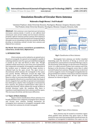
  • 1. International Research Journal of Engineering and Technology (IRJET) e-ISSN: 2395-0056 Volume: 05 Issue: 06 | June-2018 www.irjet.net p-ISSN: 2395-0072 © 2018, IRJET | Impact Factor value: 6.171 | ISO 9001:2008 Certified Journal | Page 1158 Simulation Results of Circular Horn Antenna Mahendra Singh Meena1, Ved Prakash2 1Assistant Professor, Amity University Haryana, Panchgaon, Manesar, Gurgaon, Haryana, India 2Ved Prakash, Amity University Haryana, Panchgaon, Manesar, Gurgaon, Haryana, India ---------------------------------------------------------------------***--------------------------------------------------------------------- Abstract - Horn antenna is very important part of antenna microwave antenna family. It works as very efficient feed antenna for some of most widely used microwave antennas, parabolic reflector antenna and lens antenna.Hornantennais used as feed antenna in both front feed and Cassegrainfeed.In this paper we are simulating circular horn antenna.Wewillbe focusing on simulating conical/ circular horn antenna and elliptical horn antenna. Key Words: Horn antenna, sectorial horn, pyramidal horn, conical horn, circular horn, elliptical horn. 1. INTRODUCTION A horn antenna can be realized as an opened out or flared out waveguide. An opened out waveguideiscapableof radiating radiations into free space providedthatwaveguide is excited at one side and flared at other side. Though radiation will be much less in case of two wire transmission line compared to waveguide. In waveguide asmallportionof the incident wave is radiated and the larger portion is reflected back by the open circuit. The open circuit is discontinuity which matches the waveguide to free space very poorly. Besides, diffraction around the edges will provide a poor, and a non-directional radiation pattern. Hence in order to overcome these difficulties, the one end of the waveguide is flared out in a way that it takes the shapeof electro-magnetic horn, just like an opened out transmission line which gives a dipole. If the waveguide is terminated by horn antenna, the gradual transformation takes place of abrupt discontinuity, which radiates the energy incident in forward direction, under the condition that, there is impedance matching between horn antenna and free space. This increases directivity and decreases diffraction. 1.1 Types of Horn Antenna Figure 1 shows classification of horn antennas. It is broadly divided in two categories rectangular horn antenna and circular horn antenna. Feeding mechanism for rectangular horn antennas is rectangular waveguide while for circular horn antenna its circular waveguide. Fig-1: Classification of Horn Antenna Rectangular horn antennas are further classified depending upon the direction of flaring as sectoral and pyramidal horn. Sectorial horn is formed if flaring is only in one directional. If this flaring is in the direction of electrical vector it is called sectoral E-plane horn antenna and if the flaring is in the direction of magnetic vector then it called sectoral H-plane horn antenna. If flaring is done in electrical aswell asmagnetic vector of rectangularwaveguide,thenwe get pyramidal horn antenna. Conical horn antenna isformed by flaring of circular waveguide. All four types of horn antennas are shown in figure 2. Fig-2: Types of Horn Antenna Horn antenna may be treated as transition region where guided wave becomes free space wave or finite wavefront wave starts becoming infinite wavefrontwave.As impedance of waveguide & impedance free space are not
  • 2. International Research Journal of Engineering and Technology (IRJET) e-ISSN: 2395-0056 Volume: 05 Issue: 06 | June-2018 www.irjet.net p-ISSN: 2395-0072 © 2018, IRJET | Impact Factor value: 6.171 | ISO 9001:2008 Certified Journal | Page 1159 matching, hence flaring of waveguide walls is done to avoid SWR. Other than increasing impedance of waveguide flaring also concentrates radiation in a particular direction, as a result horn antennas are highly directive and has narrower beam-width. 1.2 Design Equation of Horn Antenna The function of the electromagnetic horn is to produce a uniform phase front with a large aperture in comparison to waveguide and thus the directivity is greater. Although the principle of equality of path length is applicable to horn design but in different sense i.e. instead of specifyingthatthe wave over the plane of the horn mouth is in phase exactly, we allow that phase may deviate but an amount less the specified amount. From the geometry of the figure 3, we can write and Fig- 3: Horn Antenna path difference Where δ is permissible phase angle variation expressed as fraction of 360°. From triangle OBC (using Pythagorean Theorem) If δ is small, then δ2 can be neglected, after solving Above equations are the design equations of horn antenna. The wave front at the mouth of horn will be curved instead of plane if flare angle (2θ) is very large. The Non-uniform phase distribution over the aperture of horn results decreased directivity and increased beamwidth, similarly very small flare angle results in small aperture area for specified length L. For a given aperture distribution, the directivity is proportional to the aperture size. The maximum directivity is achieved at the largest flareanglefor which does not exceed a specified value. Typical values of flare angle are 0.25, 0.32, and 0.42 for plane horn antenna, conical horn, and H-plane horn antenna respectively. Directivity with pyramidal or conical hornantennaincreases as they have more than one flaring angle. Although derivation of exact relation for beamwidthofhornantennais possible yet approximate formula for the half power beamwidth of optimum flare horn are given by where θE & θH are Half Power Beamwidth (HPBW)inEandH direction. Directivity is given by where A = h × w = horn mouth opening area Power gain can be given by 1.3 Applications of Horn Antenna 1. If power gain needed is moderate, hornantennacan be used microwave frequencies 2. For high power gain, since the horn dimensions becomes larger, so the other antennas like lens or parabolic reflector etc. are preferred rather than horns 3. It is used as feed antenna for paraboloid reflector at microwave frequency range 4. Used for astronomical studies 2. Simulation Results In this paper we have simulated following horn antennas 1. Circular/ Conical Horn Antenna 2. Elliptical Horn Antenna For above simulation of Horn antennashave been simulated on HFSS. 2.1 Circular/ Conical Horn Antenna We have designed the conical horn antenna with the dimensions shown in figure 4. Figure 5, shows field distribution on inner surface of conical horn antenna.Figure 6 shows return losses conical horn antenna and resonance frequency is 10.95 GHz. Figure 7 and 8 shows the 3D radiation pattern of right hand circularly polarized and left hand circularly polarized conical horn antenna respectively. Figure 9 and 10 showsthe 2D radiation patternofrighthand circularly polarized and left hand circularlypolarizedconical horn antenna respectively. Following are the calculated parameters after simulations:
  • 3. International Research Journal of Engineering and Technology (IRJET) e-ISSN: 2395-0056 Volume: 05 Issue: 06 | June-2018 www.irjet.net p-ISSN: 2395-0072 © 2018, IRJET | Impact Factor value: 6.171 | ISO 9001:2008 Certified Journal | Page 1160 Table-1: Parameters after simulations for conical horn antenna Quantity Value Max U 7.752706 W/sr Peak Directivity 47.652766 Peak Gain 48.749475 Peak Realized Gain 48.712835 Radiated Power 2.044491 W Accepted Power 1.998497 W Incident Power 2.000000 W Radiation Efficiency 1.023015 Front to Back Ratio 112.788172 Er Field Value(Theta, Phi) Total 76.456132 V(0deg,120deg) X 54.155282 V(0deg,170deg) Y 53.969858 V(0deg,165deg) Z 7.893246 V(-14deg,125deg) Phi 54.157853 V(0deg,95deg) Theta 54.157853 V(0deg,5deg) LHCP 76.456013 V(0deg,145deg) RHCP 9.686929 V(24deg,5deg) Fig-4: Circular/Conical Horn Antenna - Antenna design and its parameter Fig-5: Circular/ Conical Horn Antenna – field distribution 8.00 8.50 9.00 9.50 10.00 10.50 11.00 11.50 12.00 Freq [GHz] -55.00 -50.00 -45.00 -40.00 -35.00 -30.00 -25.00 -20.00 -15.00 -10.00 Y1 ConicalHorn_Antenna_ADKv1Return Loss_Circular horn Curve Info dB(S(1,1)) Setup1 : Sw eep1 dB(S(2,2)) Setup1 : Sw eep1 Fig – 6: Circular/ Conical Horn Antenna – Return Loss Fig-7: RHCP Circular/ Conical Horn Antenna – 3D Radiation Pattern Fig 8: LHCP Circular/ Conical Horn Antenna – 3D Radiation Pattern
  • 4. International Research Journal of Engineering and Technology (IRJET) e-ISSN: 2395-0056 Volume: 05 Issue: 06 | June-2018 www.irjet.net p-ISSN: 2395-0072 © 2018, IRJET | Impact Factor value: 6.171 | ISO 9001:2008 Certified Journal | Page 1161 -200.00 -150.00 -100.00 -50.00 0.00 50.00 100.00 150.00 200.00 Theta [deg] -40.00 -35.00 -30.00 -25.00 -20.00 -15.00 -10.00 -5.00 0.00 Y1 ConicalHorn_Antenna_ADKv12D_GainRHCP_Circular horn Curve Info dB(GainRHCP) Setup1 : LastAdaptive Freq='10GHz' Phi='0deg' dB(GainRHCP)_1 Setup1 : LastAdaptive Freq='10GHz' Phi='90deg' Fig-9: RHCP Circular/ Conical Horn Antenna – 2D Radiation Pattern -200.00 -150.00 -100.00 -50.00 0.00 50.00 100.00 150.00 200.00 Theta [deg] -50.00 -40.00 -30.00 -20.00 -10.00 -0.00 10.00 20.00 Y1 ConicalHorn_Antenna_ADKv12D_GainLHCP_Circular horn Curve Info dB(GainLHCP) Setup1 : LastAdaptive Freq='10GHz' Phi='0deg' dB(GainLHCP)_1 Setup1 : LastAdaptive Freq='10GHz' Phi='90deg' Fig-10: LHCP Circular/ Conical Horn Antenna – 2D Radiation Pattern 2.2 Elliptical Horn Antenna We have designed the conical horn antenna with the dimensions shown in figure 11. Figure 12, shows field distribution on inner surface of conical horn antenna.Figure 13 shows return losses conical horn antenna and resonance frequency is 9.05 GHz. Figure 14 shows the 3D radiation pattern of right hand circularly polarized in respectively. Figure 15 and 16 shows the 2D radiation pattern of right hand circularly polarized and left hand circularly polarized conical horn antenna respectively. Following are the calculated parameters after simulations: Table 2 Parameters after simulations for Elliptical horn antenna Quantity Value Max U 4.991389 W/sr Peak Directivity 30.765393 Peak Gain 31.388849 Peak Realized Gain 31.362559 Radiated Power 2.038821 W Accepted Power 1.998325 W Incident Power 2.000000 W Radiation Efficiency 1.020265 Front to Back Ratio 314.905901 Er Field Value(Theta, Phi) Total 61.347429 V(0deg,90deg) X 42.588376 V(0deg,180deg) Y 44.155830 V(0deg,105deg) Z 11.907139 V(-22deg,75deg) Phi 55.695684 V(0deg,135deg) Theta 55.695684 V(0deg,45deg) LHCP 57.555280 V(0deg,105deSg) RHCP 21.234332 V(0deg,75deg) Fig-11: Elliptical Horn Antenna - Antenna design and its parameter Fig-12: Elliptical Horn Antenna – field distribution
  • 5. International Research Journal of Engineering and Technology (IRJET) e-ISSN: 2395-0056 Volume: 05 Issue: 06 | June-2018 www.irjet.net p-ISSN: 2395-0072 © 2018, IRJET | Impact Factor value: 6.171 | ISO 9001:2008 Certified Journal | Page 1162 8.00 8.50 9.00 9.50 10.00 10.50 11.00 11.50 12.00 Freq [GHz] -45.00 -40.00 -35.00 -30.00 -25.00 -20.00 -15.00 Y1 EllipticalHorn_Antenna_ADKv1Return Loss_Elliptical horn Curve Info dB(S(1,1)) Setup1 : Sw eep1 dB(S(2,2)) Setup1 : Sw eep1 Fig-13: Elliptical Horn Antenna – Return Loss Fig-14: RHCP Elliptical Horn Antenna – 3D Radiation Pattern -200.00 -150.00 -100.00 -50.00 0.00 50.00 100.00 150.00 200.00 Theta [deg] -50.00 -40.00 -30.00 -20.00 -10.00 -0.00 10.00 Y1 EllipticalHorn_Antenna_ADKv12D_GainRHCP_Elliptical horn Curve Info dB(GainRHCP) Setup1 : LastAdaptive Freq='10GHz' Phi='0deg' dB(GainRHCP)_1 Setup1 : LastAdaptive Freq='10GHz' Phi='90deg' Fig-15 RHCP Elliptical Horn Antenna – 2D Radiation Pattern -200.00 -150.00 -100.00 -50.00 0.00 50.00 100.00 150.00 200.00 Theta [deg] -40.00 -30.00 -20.00 -10.00 0.00 10.00 20.00 Y1 EllipticalHorn_Antenna_ADKv12D_GainLHCP_Elliptical horn Curve Info dB(GainLHCP) Setup1 : LastAdaptive Freq='10GHz' Phi='0deg' dB(GainLHCP)_1 Setup1 : LastAdaptive Freq='10GHz' Phi='90deg' Fig-16 LHCP Elliptical Horn Antenna – 2D Radiation Pattern 3. Conclusion The results of simulation are quite similar to what we have studied in theory of Antenna. The simulation givesgreatdeal of understanding. By varying size of horn opening we can very gain, bandwidth and resonance frequency of antenna. References [1]. Mahendra Singh Meena, Nisha Achra, “A text book on Antenna and Wave Propagation” CBC Publication, 2012 [2]. Maudhoo Jahnavi, Neha Yadav, Krishanu Griyagya, Mahendra Singh Meena, Ved Prakash. “Vehicle to Vehicle Communication for Collision Avoidance”, Volume 6, Issue V, International Journal for Research in Applied Science and Engineering Technology (IJRASET) Page No:, ISSN : 2321-9653 [3]. Puneet Kumar, Mahendra Singh Meena, Ved Prakash, “Bandwidth Enhancement of a Patch Antenna by using Metamaterials for WLAN Application”, Vol 01, Issue 04, Current Research in Engineering, Science and Technology (CREST) Journals , June 2013, ISSN [ 2320-706X ] 105-109 [4]. Mahendra Singh Meena, “Bandwidth Enhancement Using Single Slot in Heptagonal Microstrip Patch Antenna”, Volume: 04, Issue: 05, International Research Journal of Engineering and Technology (IRJET), May -2017, ISSN: 2395 -0056, 1416-1419 [5]. Mahendra Singh Meena, “Bandwidth Improvement of Slotted Patch Antenna using Pin Short”, International Journal for Research in Applied Science & Engineering Technology (IJRASET), Volume 5 Issue V, May 2017, 1356- 1362 ISSN: 2321-9653 [6]. Mahendra Singh Meena, “High Bandwidth Microstrip Antenna of Elliptical Patch with Square Slot and a Pin Shot”, GE-International Journal of Engineering Research, Vol. 5, Issue 5, May 2017 ISSN 2321-1717, 5-14 [7]. G.J.Deepika, Gurpreet Kaur, Neha Kumari, Suruchi, Sonal Dahiya, Mahendra Singh Meena, “Railway Accident Monitoring”, International Journal on Recent and Innovation Trends in Computing and Communication, Volume: 5 Issue: 5, ISSN: 2321-8169, 704 – 706