

Recommended
Recommended
More Related Content
What's hot
What's hot (20)
Viewers also liked
Viewers also liked (20)
Similar to M010327985
Similar to M010327985 (20)
More from IOSR Journals
Recently uploaded
Recently uploaded (20)
M010327985
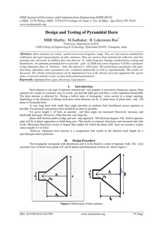
- 1. IOSR Journal of Electronics and Communication Engineering (IOSR-JECE) e-ISSN: 2278-2834,p- ISSN: 2278-8735.Volume 10, Issue 3, Ver. II (May - Jun.2015), PP 79-85 www.iosrjournals.org DOI: 10.9790/2834-10327985 www.iosrjournals.org 79 | Page Design and Testing of Pyramidal Horn MBR Murthy; M.Sudhakar; B. Lokeswara Rao* Professors, Department of ECE, CMR College of Enginnering & Technology, Hyderabad 501401, Telangana, India. Abstract: Horn antennas are widely used in microwave frequency range. They are also used as standard for calibration and gain measurements of other antennas. They are used as feed elements for reflectors and lens antennas and universal. In addition they also find use in radio frequency heating, nondestructive testing and biomedicine. An optimum pyramidal horn to provide gain of 20dB and center frequency 9.5GHz is designed. Using aluminum sheet of thickness 2mm, the antenna is fabricated. The performance parameters like gain, directivity, impedance and s parameters are evaluated analytically as well as experimentally. The results are discussed. The scheme of measurement can be implemented even in the absence of costly equipment like power meter or network analyzer to get an idea of the antenna parameters. Keywords: Optimum Horn, gain, directivity, S parameters. I. Introduction Horn antenna is one type of aperture antenna and very popular in microwave frequency region. Horn antennas are simple to construct, easy to excite, can provide high gain and have a wide impedance bandwidth, The horn antenna is obtained by flaring a hollow pipe of rectangular cross section to a larger opening. Depending on the direction of flaring microwave horn antennas can be E plane horn, H plane horn , and EH plane or Pyramidal horn. A very long horn with small flare angle provides as uniform field distribution across aperture as possible. For practical convenience horn should be as short as possible For given length L of horn, as aperture and flare angle are increased Directivity increases and bandwidth decreases. However, if they become very large the phase shift between paths at edge and axis may approach 180 electrical degrees. The field at aperture edge will be in phase opposition to field along axis. This results in reduced directivity and increased side lobe levels. Maximum directivity occurs at largest flare angles for which the phase shift does not exceed a certain value (usually 0.1 to 0.4λ). However. Optimum horn antenna is a compromise that results in the shortest axial length for a specified gain and is preferred . II. Design Procedure The rectangular waveguide with dimensions axb is to be flared to a horn of aperture AxB. The cross sectional view of flared wave guide in E and H planes and dimensions of horn are shown figure 1. Figure1- Dimensions of horn antenna
- 2. Design and Testing of Pyramidal Horn DOI: 10.9790/2834-10327985 www.iosrjournals.org 80 | Page The required dimensions of sides can be estimated by solving a single fourth-order equation. The equation to be solved for designing optimum horn is 𝐴4 − 𝑎𝐴2 + 3𝑏𝐺 𝜆2 8𝜋𝜀 𝑎𝑝 𝐴 − 3𝐺2 𝜆4 32𝜋2 𝜀 𝑎𝑝 2 = 0………(1) For the horn to be realizable, it is necessary that RE= RH=RP A useful solution to design optimum horn for a given gain G and operating frequency f is obtained as follows. Calculate the first approximate value of A using A=0.45λ Find𝐵 = 1 4𝜋 𝐺𝜆2 0.51𝐴 ……(2) Find 𝑅1 = 𝐴2 3𝜆 …….(3) Find 𝑅2 = 𝐵2 2𝜆 …….(4) Calculate ….(5) Calculate ……(6) Check if RE=RH is satisfied or not. If not, change the approximation of A and repeat the above procedure till RE=RH. is satisfied. Finally note the dimensions for antenna fabrication. Using the above procedure, an optimum horn is designed to provide a gain of 20dB at 9.5GHz.The feed waveguide has dimensions of a=2.286 cms and b=1.016cms.. The iterations are shown in table 1. III. Fabrication The horn antenna is fabricated by welding aluminum sheet of thickness 2mm. The fabricated antenna is shown in figure2. Figure-2 Fabricated horn antenna IV. Performance Evaluation The characteristics of horn half-power beamwidth, Directivity and gain can de estimated analytically using relations. They can be evaluated from experimental observations. The relations are (a) Half Power Beam Widths Optimum E-plane rectangular horn = 56/aEλ Optimum H-plane rectangular horn= 67/aHλ (b) The directivity of horn antenna 𝐷 = 4𝜋 𝜃 𝐻𝑃 𝛷 𝐻𝑃 … (9) Directivity (dB) =10 log D (c) Gain in dB G dB= 8.1 +10 log (AB/λ2 ) (d) efficiency η(dB) = Gain(dB) – Directivity(dB) and Efficiency = 10 𝜂(𝑑𝐵 ) 10
- 3. Design and Testing of Pyramidal Horn DOI: 10.9790/2834-10327985 www.iosrjournals.org 81 | Page To measure these parameters along with impedance and s parameters of horn experimentally; X band Reflex Klystron powered microwave bench is used. In these measurements the crystal input current is kept below 20μA so that it acts like a square law device and voltage or current measurements made at crystal output are proportional to input power. The bench set up and procedure is explained below. Figure-3 Radiation pattern measurement setup The microwave oscillations are generated and crystal current is adjusted to about 20 micro-amperes. With the help of rotating mechanism the radiation intensity of horn as a function of Φ the azimuth angle and θ the elevation angle are observed and the half power beam widths ΦHP and θ HP in azimuth and elevation are found. The distance between transmitter and receiver is d=139cms. The Directivity of the antenna is calculated using the relation (9). With the same set up and orienting the antennas for maximum reception gain of the antenna is evaluated using 3 antenna method. For this the fabricated antenna A1 and two other standard horn antennas A2 and A3 are used. Three sets of power transmitted and power received are measured using antennas1 ,2; 1,3; and 2,3 respectively. In view of very small value of current at receiving antenna an operational amplifier with gain 200 is used to improve the accuracy of measurement. For free space communication link the Friis transmission formula is tr 2 tr GG R4 PP ….(10) where Pr = power received. Gt=gain of transmitting antenna, Gr = gain of receiving antenna, R= distance between transmitter and receiver and λ= wavelength of signal If G1, G2 and G3 are the gains of the antennas A1, A2, and A3 used, then using Friss formula the following three simultaneous equations can be formed for each fabricated antenna.. A=G1+G2 with {A2 Tx, A1 Rx} …(11) = 20 log (4πR/λ) + 10 log (Pr/Pt) } B= G1 +G3 with { A3 Tx, A1 Rx }….(12) = 20 log (4πR/λ) + 10 log (Pr/Pt) C= G2+G3 with {A3 Tx, A2 Rx}….(13) =20 log (4πR/λ) + 10 log (Pr/Pt) To measure the impedance of horn antenna the set up used is shown in fig 4. Fig 4 Impedance measurement set up
- 4. Design and Testing of Pyramidal Horn DOI: 10.9790/2834-10327985 www.iosrjournals.org 82 | Page With short circuit termination the location of two successive minima are found. Then the shorting plate is replaced by horn antenna. The location of minimum the value of maximum and minimum field values are recorded. The standing wave ratio is calculated. With this value of SWR and the shift of minimum using a Smith Chart the normalized load impedance zn of antenna is found. The impedance of antenna is ZA is found from ZA=znxZo .where Zo is the characteristic impedance of wave guide and 𝑍 𝑜 = 120 𝜋 1−( 𝑓 𝑐 𝑓 )2 where fc= 6.56GHz for a WR90 waveguide and f=9.5GHz .To measure the magnitude of scattering parameter S11 the measurement set up is arranged as shown in figure 5. Fig 5 S11 magnitude measurement set up In this experiment a circulator is used. The source is connected to port 1 of circulator. Antenna is connected to port 2 and micro-ammeter2 is connected to port 3. Reading of micro ammeter 2 will indicate the power reflected from antenna input port. The ratio of power reflected to power input gives S11. In all measurements in view of very small value of current at receiving antenna an operational amplifier with gain 200 is used to improve the accuracy of measurement. The results of the parameters calculated from experimental observations and estimated from theoretical expressions are presented in the next section and discussed. V. Results And Discussions Design Specifications: G=20dB=100, f=9.5GHz; WR90 waveguide a=2.286cms , b=1.016 cms A B R1 R2 Re Rh Re-Rh 14.21 10.94 21.31 18.96 15.91 19.31 -3.4 14.3 10.87 21.59 18.72 15.72 19.55 -3.83 14 11.1 20.69 19.53 16.34 18.78 -2.44 13.8 11.26 20.11 20.1 16.77 18.28 -1.51 13.6 11.43 19.53 20.69 17.21 17.78 -0.56 13.4 11.6 18.96 21.31 17.68 17.28 0.4 13.5 11.51 19.24 21 17.44 17.53 -0.08 13.49 11.52 19.21 21.03 17.47 17.5 -0.04 13.48 11.53 19.19 21.06 17.49 17.48 0.01 13.47 11.54 19.16 21.09 17.51 17.45 0.06 Table-1 calculation of dimensions of the optimum horn The iteration values are rounded to one decimal place and the final dimensions obtained are: A =13.5cm; B=11.5cm; R1=19.2 cm; R2=21.1cms; RE=RH= 17.5 cm. From theoretical relations the estimated values are (a) 𝐻𝑃𝐸 = 56 𝑜 𝜆 𝐴 = 13.09 𝑜 =0.2204 rad 𝐻𝑃𝐻 = 67 𝑜 𝜆 𝐵 = 18.39 𝑜 =0.3209 rad The directivity of horn antenna can be estimated from (b) 𝐷 = 4𝜋 𝜃 𝐻𝑃 𝛷 𝐻𝑃 = 4𝜋 𝜃 𝐻𝑃 𝛷 𝐻𝑃 =177.99=178 or 22.5dB (c) Gain from relation G (dB) = 8.1+10 log (AB/ λ2 )
- 5. Design and Testing of Pyramidal Horn DOI: 10.9790/2834-10327985 www.iosrjournals.org 83 | Page G =20.02dB =100.46 (d) efficiency Gain/Directivity =100.46/178= 0.564or 56.4% Or G dB-DdB= 20.02-22.5=-2.48dB=0.565 or 56.5% From experimentally observed values the radiation patterns in elevation and azimuth are plotted and shown in figure 5a,5 θHP=170 Figure-6a radiation pattern ΦHP =160 Figure-6b radiation pattern i. Half Power Beam Width of the antenna from Pattern are ΦHP= 16o =0.279 radians ; ΘHP=17o =0.2967radians ii. Directivity D= [4π/(ΦHP θHP)] = 151.8= 21.8dB iii. For measurement of gain of fabricated antenna by three antenna method the readings obtained resulted in the following simultaneous equations : A = 34.92 ; B=35.94 ; C=32.08 Gain of antenna1 G1= (A-C+B)/2 = 19.49dB Efficiency=19.49-21.8= -2.31dB=0.587 or 58.7% Impedance measurement: With short circuit termination location of minimum1is 8.74 cm and minimum 2 is 11.07cm.With horn antenna Imax =3μA and Imin=1.75μA. location of minimum= SWR= 𝐼 𝑚𝑎𝑥 𝐼 𝑚𝑖𝑛 = 3 1.75 = 1.309 Shift in minimum =0.156λ Drawing The plotting on smith chart is shown in figure 7.
- 6. Design and Testing of Pyramidal Horn DOI: 10.9790/2834-10327985 www.iosrjournals.org 84 | Page Figure 7 Zn= 1.2-j0.15; Zo= 521.2 ohms;ZA= 625.4-j78.2 ohms Length of line from center to point P=.65 cms=0.007 m Therefore magnitude of ρ=0.007 which will be S11. Evaluation of S11 and S12: From the experimentally measured values when input to the port-1 of the circulator is , Pt = 348mV,the power out at port 3 of circulator is found to be Pr=2.6mv. So S11 = Pr / Pt =2.6/348= 0.0074 which agrees well with the value of ρ=0.007 obtained from Smith chart. Since the second port of antenna cannot be connected to source S22 will be zero and S12=S21 can be found using relation efficiency ɳ= |S21|2 / (1-|S11|2 ). or |S21| = 𝜂(1 − |𝑆11|2 From experimental observations ɳ=0.587 S12=√[0.587x(1-|0.0074|2 )] =0.7661. S-matrix is 𝑆 = 𝑆11 𝑆12 𝑆21 𝑆22 S matrix of the antenna will be 𝑆 = 0.0074 0.7661 0.7661 0 and Normalized S matrix is 𝑆 = 0.009 1 1 0 There is very good agreement between the theoretically estimated and practically obtained values of half power beam width, gain, directivity and scattering coefficients. In view of very small value of current at receiving antenna an operational amplifier with gain 200 is used to improve the accuracy of measurement. With this scheme it is possible to get a first approximate idea about the magnitudes of various parameters in spite of non-availability of costly and sophisticated bolometer and spectrum analyzer. This will help to modify design if required.
- 7. Design and Testing of Pyramidal Horn DOI: 10.9790/2834-10327985 www.iosrjournals.org 85 | Page References [1]. C.A. Balanis, Antenna theory: Analysis and design, Wiley, New York, 1997 [2]. Antenna theory and design by Warren L Stutzman and Gary A Thile , 2nd edition, Wiley [3]. Practical Antennas- Antenna Measurements by Michael Hillbun Authors Profiles M B R Murthy graduated B.Tech from Andhra University College of Engineering,Visakhapatnam in 1972,with specialization in Electrical Engineering.He received his MS(Engg.) from Regional Engineering College,Rourkela during 1972-74 with specialization in Communication Systems..He received his Ph.D from Karanatak University in 1990.He worked on Microwave applications on Dielectric Studies.He is in the academic filed for the past 40years. Currently he is working as a senior Professor & Dean PG Studies in the department of ECE, CMR College of Engineering and Technology, Hyderabad, 501041, India. He has 104 publications to his credit in International Journals and Conferences. His areas of interest are Speech Processing, and Communications. He is a member of several professional bodies : Senior member IEEE, Life Fellow Institute of Electronics and Telecommunication Engineers, India , Life member Institution of Engineers India, Life member Instrument society of India, Life member Indian Society for Technical Education M. Sudhakar graduated B.Tech from JNTU College of Engineering, Hyderabad in 1979, with specialization in ECE. Later he completed his M.Tech from Indian Institute of Technology Madras in 1986 with the specialization in Instrumentation, Control & Guidance. Successfully Completed R&D Project assigned by IAF on “Mathematical Modelling & Simulation of Aero Engine Control System‟ at Aeronautical Development Establishment, Bangalore and Gas Turbine Research Establishment, Bangalore.He is presently working as a Professor & Vice-principal in the department of ECE at CMR College of Engineering & Technology, Hyderabad. Bhogadi Lokeswara Rao was born on Jan 4,1968.He received his Bachelor’s degree in Electronics & Communication Engineering from Andhra University, and Master’s degree in Microwave & Radar Engineering from Osmania University. He is currently working as Professor & HOD in the Department of Electronics & Communication Engineering, CMR College of Engineering & Technology ,Hyderabad. He had submitted his Ph.D to the Andhra University in 2014 . He has 24 years of experience in Teaching, R&D, and Industry. He is working in the area of GPS/INS Integration using Kalman filtering. He is a Fellow of IETE and also a Fellow of IE (India).