SlideShare a Scribd company logo
1 of 10
Download to read offline
International Research Journal of Engineering and Technology (IRJET) e-ISSN: 2395-0056
Volume: 05 Issue: 04 | Apr-2018 www.irjet.net p-ISSN: 2395-0072
© 2018, IRJET | Impact Factor value: 6.171 | ISO 9001:2008 Certified Journal | Page 138
Design and Analysis of Friction Stir Welding Using Dissimilar Alloys (AA
6061 and AA 6082) Aluminum Alloys
Ravinder Reddy1, Abhishek tandle2, Sanne Srikanth3, Ramandeep Singh4 , Ramdeep kolli5
1Associate Professor, Dept. of Mechanical Engineering, VJIT college, Telangana, India
2345 Student, Dept. of Mechanical Engineering, VJIT college, Telangana, India
--------------------------------------------------------------------------***----------------------------------------------------------------------------
Abstract: Friction stir welding (FSW) is a new solid-state joining process and this joining technique is energy efficient, versatile
and environment friendly. Frequently it can be used to join high-strength aerospace aluminum alloys and other metallic alloys
that are hard to weld by conventional fusion welding. FSW is considered to be the most significant development in metal joining
in a decade. The scope of this investigation is to evaluate and experiment the effect of joining parameters on the mechanical
properties of dissimilar aluminum alloys (AA 6082 and AA 6061 Aluminum Alloy) joints produced using friction stir welding.
Friction stir weld was performed on the dissimilar aluminum alloys using different rotational speeds and traverse speeds and the
influence of these parameters on the mechanical performance of the weld has been investigated in terms of hardness, tensile
testing and statistical analysis.
Key Words: Friction stir welding, RSM, Al Alloy 6061, Al Alloy 6082.
1. Introduction
Friction stir welding (FSW) is a relatively new and promising solid state joining process developed and patented by The
Welding Institute (TWI), Cambridge, U.K., Figure 1.1 shows the schematic drawing of FSW process. The work piece is placed on
a backup plate and clamped rigidly by a fixture to prevent lateral movement during FSW. A specially designed frustum shaped
tool with a pin extending from the shoulder is rotated with a speed of several hundred rpm and slowly pushed into the joining
line. The pin usually has a diameter one-third of the shoulder and typically has a length slight less than the thickness of the
work piece. The pin is forced into the work piece at the joint until the shoulder contact the surface of the work piece (figure 1.2
a). As the tool descends further, its surface friction with work piece creates more heat and later plasticizes a cylindrical metal
column near the inserted pin and the immediate material under the shoulder. The weld usually thins the parent metal by
about 3-6 % of original thickness. The work piece to be joined and the tool are moved are similar to each other such that the
tool tracks along the weld interface and the rotating tool provides the ‘stir’ action. The plasticizing metal within a narrow zone
moves while transporting metal from the leading face of the pin to the trailing edges. As the tool passes, the weld cools,
thereby joining the two plates together (figure 1.2 b). On tool extraction a hole is left as the tool is withdrawn from the work
piece (figure 1.2 c).
Figure 1.1 Schematic drawing of friction stir welding
International Research Journal of Engineering and Technology (IRJET) e-ISSN: 2395-0056
Volume: 05 Issue: 04 | Apr-2018 www.irjet.net p-ISSN: 2395-0072
© 2018, IRJET | Impact Factor value: 6.171 | ISO 9001:2008 Certified Journal | Page 139
Figure 1.2 Description of the three main stages of FSW (a) plunge phase (b) translational and rotational motion of the tool
through the plates (c) tool extraction
2. Principle of friction stir welding
The basic principal of Friction stir welding is heating the metal to a temperature below re-crystallization temperature using
Friction generated by the cylindrical shouldered tool on metal. This tool having characteristic profile pin, which is rotated and
pushed into the joint area between two pieces of sheet or the plate material. The parts have to be done secure clamping using
the fixtures to prevent the joint faces from being forced apart. The Frictional heat is produced between the wear-resistant
welding tool and the experimental work pieces, which causes the metals or alloys to soften without reaching the melting point.
The tool moves along the joint line of the work materials. The plasticized material gets transferred to the moving edge of the
tool pin and forced through similar contact with the tool shoulder and pin profile. The cooling of the material leads to the
creation of a solid phase bond between the clamped work pieces.
3. Properties of material Aluminum Alloys AA 6082 and AA 6061 and process parameters
The test plates of size 160 mm X 80 mm X 8 mm are prepared from aluminum alloy AA6082 plates using CNC cutting machine.
The chemical composition and mechanical properties of the base material are presented in Table 1 and Table 2, respectively.
3.1 Chemical Composition
Table 1. Chemical composition of aluminum alloy 6082 and 6061
Elements Mg Mn Fe Si Cu Cr Al
6061 1.1 0.12 0.35 0.58 0.22 0.04 Bal
6082 0.60-
1.20
0.40-
1.00
0.50 0.70-
1.30
0.10 0.25 95.2-
98.3
3.2 Physical Properties
Table 2. Physical properties of aluminum alloy 6082 and 6061
Base metal Density(kg/m3) Melting temp
ᵒC
Modulus of
elasticity GPa
Poisson’s
Ratio
6061 2700 580 69 0.33
6082 2710 555 69 0.33
International Research Journal of Engineering and Technology (IRJET) e-ISSN: 2395-0056
Volume: 05 Issue: 04 | Apr-2018 www.irjet.net p-ISSN: 2395-0072
© 2018, IRJET | Impact Factor value: 6.171 | ISO 9001:2008 Certified Journal | Page 140
3.3 Mechanical Properties
Table 3. Mechanical properties of aluminum alloy 6082 and 6061
Base Metal Yield stress,
M pa
Ultimate
tensile
strength, Mpa
Hardness
number, BHN
Elongation %
6061 235 283 95 10-13 %
6082 250 140 to 330 95 10%
4. Welding Tool
The welding tool of FSW plays a prominent role welding process which has an impact in the mechanical properties and quality
of microstructure of the material. Therefore the tool is designed carefully which may alter the weld quality. The tool should
have idealistic and higher mechanical properties than weld materials. The difficulties associated are mainly with finding
proper tool material. The experiment is conducted using FSW machine shown in Fig. 1 to fabricate the joints. The welding was
done by single pass.
Fig 1. FSW machine Fig 2. Tool pin profile
From the different tool materials like tool steel, carbon boron nitride, carbide, high carbon, high speed steel and high
chromium steel (HCHCr). H13 is chosen as tool material because of its high strength, high hot hardness, easy to process, easily
available and low cost. The FSW tools are manufactured using CNC Turning center and wire cut EDM machine. Fig 3 shows the
tool designing and experimentation of the tool with the help of solid works auto desk.
Fig 3. Tool designed using solid works software
International Research Journal of Engineering and Technology (IRJET) e-ISSN: 2395-0056
Volume: 05 Issue: 04 | Apr-2018 www.irjet.net p-ISSN: 2395-0072
© 2018, IRJET | Impact Factor value: 6.171 | ISO 9001:2008 Certified Journal | Page 141
The friction stirring tool consists of a pin, or probe, and a shoulder. Contact of the pin with the work piece creates frictional
and deformational heating and softens the work piece material; contacting the shoulder to the work piece increases the work
piece heating, expands the zone of softened material, and constrains the deformed material. Fig 4. shows the most important
tool parts.
Fig 4. Tool pin and important parts
Naturally, the important effects to the tool during welding are high temperature, abrasive wear and dynamic effects.
Therefore, the good tool materials will be having the properties of good wear resistance, high temperature strength,
temperature resistance, good toughness.
5. Plan of Investigation
The follow a line of investigation work was to be carried out in the following steps:
1. Identifying the imperative process parameter.
2. Finding the upper and lower limits of the process parameter Viz. tool rotational speed (N), welding speed (S), and axial force
(F)
3. Development of design matrix
4. Conducting the experiments as per the design matrix
5. Recording the responses, viz. Ultimate Tensile Strength (UTS), Yield Strength (YS), Percentage of Elongation (POE)
6. Development of the mathematical model
7. Checking the satisfactoriness of the models developed
8. Conducting the consistency test runs and comparing the results.
9. Presenting the special effects of the process parameters on the mechanical properties in graphical form and analyzing the
results.
5.1 Important process parameter
Based on initial trials, the independent process parameters affecting the mechanical properties were identified as: tool
rotational speed (N), welding speed (S) and Tilt angle (T)
5.2 Finding the limits of control variable
Test runs are conducted to find the upper and lower limit of process parameters, by varying one of the parameter and keeping
the rest of them at constant values. The upper limit of a factor was coded as +2 and lower limit as -2. The intermediate coded
values being calculated from the following relationship
Xi=2 [2X-(Xmax+Xmin)]/(Xmax-Xmin)
Shoulder
Pin
International Research Journal of Engineering and Technology (IRJET) e-ISSN: 2395-0056
Volume: 05 Issue: 04 | Apr-2018 www.irjet.net p-ISSN: 2395-0072
© 2018, IRJET | Impact Factor value: 6.171 | ISO 9001:2008 Certified Journal | Page 142
Where Xi is the required coded value of a variable X; and X is any value of the variable from Xmin to Xmax, Xmin is the lower
limit of the variable and Xmax is the upper limit of the variable. The selected process parameters with their limits, units and
notations are given in Table 4.
Table 4 : Process parameter and its levels
Std 1 2 3 4 5 6 7 8 9
Tool Speed 900 1120 1120 1120 1120 1120 1400 1400 1400
Feed rate 100 60 80 100 125 165 80 100 125
Degree 1.5 1.5 1.5 1.5 1.5 1.5 1.5 1.5 1.5
5.3 Development of Design Matrix
The selected design matrix is shown in Table 5. It is a three factor five level central composite rotatable designs consisting of
20 sets of coded conditions composed of a full factorial 23 = 8, plus 6 centre points and 6 star points thus 20 experimental runs
allowed the estimation of the linear, quadratic and two way interactive effects of the process parameter on the mechanical
properties.
5.4. Conducting the experiment as per the design matrix
The experiments were conducted as per the design matrix at random, to avoid the possibility of systematic errors infiltrating
in to the system.
5.5 Recording of the responses
Tensile test specimens are prepared as per ASTM E8 standard shown in Fig. 6 and transverse tensile properties such as
ultimate tensile strength, yield strength, and percentage of elongation of the FS welded joints are evaluated using
computerized UTM. For each welded plate, three specimens are prepared and tested. Fig. 5 shows tensile specimen after
fracture of weld. The average values of the results obtained from those specimens are tabulated and presented in Table 5
Fig 5. Typical tensile specimen
Fig 6. Tensile specimen after fracture
International Research Journal of Engineering and Technology (IRJET) e-ISSN: 2395-0056
Volume: 05 Issue: 04 | Apr-2018 www.irjet.net p-ISSN: 2395-0072
© 2018, IRJET | Impact Factor value: 6.171 | ISO 9001:2008 Certified Journal | Page 143
Table 5: Estimated mechanical properties
Std UTS
N/mm2
Elongation
%
Yield Stress
N/mm2
1 196.941 9.520 181.262
2 181.888 8.720 151.767
3 190.237 7.960 155.051
4 199.403 9.560 161.194
5 182.157 7.000 177.446
6 169.984 5.560 143.312
7 108.138 1.920 98.476
8 195.351 7.520 159.015
9 201.178 8.980 184.574
5.6 Development of mathematical model
Ultimate tensile strength, yield strength, and percentage of elongation of the joints are functions of rotational speed, welding
speed, and tilt angle and it can be expressed as
Y = f (N, S, T)
Where
Y-The response
N- Rotational speed, rpm
S- Welding Speed, mm/s
T–Tilt angle, degrees
For the three factors, the selected polynomial (regression) could be expressed as
UTS= 713.416 + -0.683336 * Tool Rotation + -1.69573 * Weld Feed + -0.00125722 * Tool Rotation * Weld Feed +
0.000305072 * Tool Rotation^2 + 0.0168008 * Weld Feed^2
YS= -69.434 + 0.134205 * Tool Rotation + 3.0318 * Weld Feed + -0.00423627 * Tool Rotation * Weld Feed +
0.000100582 * Tool Rotation^2 + 0.0130571 * Weld Feed^2
EL= 62.7155 + -0.0531229 * Tool Rotation + -0.414824 * Weld Feed + -4.7619e-05 * Tool Rotation * Weld Feed +
2.21365e-05 * Tool Rotation^2 + 0.00234346 * Weld Feed^2
The equation in terms of coded factors can be used to make predictions about the response for given levels of each factor. By
default, the high levels of the factors are coded as +1 and the low levels are coded as -1. The coded equation is useful for
identifying the relative impact of the factors by comparing the factor coefficients.
DESIGN EXPERT 9 software packages are used to calculate the values of those coefficients for different responses and are
presented in Table 5. After determining the coefficients, the mathematical models are developed.
International Research Journal of Engineering and Technology (IRJET) e-ISSN: 2395-0056
Volume: 05 Issue: 04 | Apr-2018 www.irjet.net p-ISSN: 2395-0072
© 2018, IRJET | Impact Factor value: 6.171 | ISO 9001:2008 Certified Journal | Page 144
5.7 Developed final mathematical model
The developed final mathematical model equations in the coded form are given below table 6
Regression
Coefficient
Ultimate tensile
strength
Yield stress Elongation
A 295.61 339.73 0.7727
B 109.38 556.86 0.1263
AB 62.73 712.28 0.0900
A² 248.72 27.04 1.31
B² 503.25 303.96 9.79
UTS = 177.077 + -6.07871 * A + 3.69766 * B + -3.96025 * AB + 5.97941 * A^2 + 8.50541 * B^2
YS = 160.174 + -6.51657 * A + 8.34312 * B + -13.3442 * AB + 1.9714 * A^2 + 6.61015 * B^2
EL=7.87308 + -0.31079 * A + 0.125659 * B + -0.15 * AB
5.8 Checking the adequacy of the developed model
The adequacy of the models so developed is then tested by using the analysis of variance technique (ANOVA). Using this
technique, it is found that calculated F ratios are larger than the tabulated values at a 95% confidence level; hence, the models
are considered to be adequate. Another criterion that is commonly used to illustrate the adequacy of a fitted regression model
is the coefficient of determination (R2 ). For the models developed, the calculated R2 values and adjusted R2 values are above
70%. These values indicate that the regression models are quite adequate. The results of the ANOVA are given in Table 6. The
validity of regression models developed is further tested by drawing scatter diagrams. Typical scatter diagrams for all the
models are presented in Fig. 7-9. The observed values and predicted values of the responses are scattered close to the 45° line,
indicating an almost perfect fit of the developed empirical models.
Fig. 7: Scatter diagram of the ultimate Fig. 7: Scatter diagram of the yield stress
Tensile strength, Mpa
International Research Journal of Engineering and Technology (IRJET) e-ISSN: 2395-0056
Volume: 05 Issue: 04 | Apr-2018 www.irjet.net p-ISSN: 2395-0072
© 2018, IRJET | Impact Factor value: 6.171 | ISO 9001:2008 Certified Journal | Page 145
Fig. 9: Scatter diagram of the percentage of elongation.
Table 7: ANOVA test results
Response Sum of squares Degree of
freedom
Mean square F –
value
P -
value
Model Residual Model Residual Model Residual
UTS 1921.53 5727.24 5 7 384.31 818.18 0.4697 0.7887
YS 1921.53 5727.24 5 7 384.31 818.18 0.4697 0.7887
EL 11.33 42.23 5 7 2.27 6.03 0.3757 0.8507
6. Analysis of the Results
The effects of the different process parameter on the mechanical properties of FS welded aluminum alloy AA6082 and
AA6061 are predicted from the mathematical models using the experimental interpretation are available in Figures
10showing the general trends between cause and effect. Effect of rotational speed (N) Fig. 10 shows the direct outcome of
rotational speed on mechanical properties. It is seen that as the rotational speed increases the tensile strength, yield strength
and percentage of elongation of FS welded aluminum alloy AA6082 and AA6061 increases and then it decreases. The highest
rotational speed results in the metallurgical transformation such as solubilisation, re-precipitation, and coarsening of
strengthening precipitates at the weld zone and lowering of dislocation density which decrease the tensile strength of the FS
welded joints. It is clear that in FSW as the rotational speed increases the heat input also increases. More heat input destroys
the regular flow behavior.
International Research Journal of Engineering and Technology (IRJET) e-ISSN: 2395-0056
Volume: 05 Issue: 04 | Apr-2018 www.irjet.net p-ISSN: 2395-0072
© 2018, IRJET | Impact Factor value: 6.171 | ISO 9001:2008 Certified Journal | Page 146
Fig 10. Effect of tool rotation on properties
Confirmation experiments
Experiments are conducted to verify the regression equations of UTS, YS and EL. Nine weld runs are made using different
values of rotational speed, welding speed and tilt angle other than what were used in the design matrix. The results obtained
are quite satisfactory and the details are presented in Table 8
Table 8: Confirmation results
Response Predicted
mean
Predicted
Median
Standard
Deviation
SE
Prediction
95% PI
Low
95% PI
High
UTS 177.077 177.077 30.5323 33.4465 97.9885 256.165
YS 160.174 160.174 28.6038 31.3339 86.0813 234.267
EL 6.876 6.876 2.45612 2.69055 0.513861 13.2381
7. Conclusions
The following conclusions are arrived at from the above investigations.
1. The relations between process parameters for FS welding of AA6082 and AA6061 aluminum alloy have been established.
The response surface methodology was adopted to develop the regression models, which were checked for their adequacy
using ANOVA test, scatter diagrams and found to be satisfactory.
2. Confirmation tests have shown the development model is reasonably correct.
3. The increase in the tool rotational speed, welding speed and tilt angle to the increase in the ultimate tensile strength and it
reaches a maximum value and then it decreases. This inclination is common for yield strength and percentage of elongation.
References
[1] R. Nandan, T. DebRoy and H. K. D. H. Bhadeshia, “Recent advances in friction stir welding–process, weldment structure and
properties”, Progress in Materials Science, vol.53, 980-1023, (2008)
International Research Journal of Engineering and Technology (IRJET) e-ISSN: 2395-0056
Volume: 05 Issue: 04 | Apr-2018 www.irjet.net p-ISSN: 2395-0072
© 2018, IRJET | Impact Factor value: 6.171 | ISO 9001:2008 Certified Journal | Page 147
[2] Jae-Hyung Cho, E. Donald, Boyce and Paul R. Dawson, “Modeling strain hardening and texture evolution in friction stir
welding of stainless steel”, Material Science Engineering A, 398, 146-163. (2005).
[3] C. J. Dawes and W. M. Thomas, “Friction stir process welds aluminum alloys”, Welding Journal 75, 41-44, (1996).
[4]H. Uzun, C.D. Donne, A. Argagnotto, T. Ghidini and C. Gambaro, “Friction stir welding of dissimilar Al 6013-T4 to X5CrNi18-
10 stainless steel”, Materials and Design, 26, 41- 46, (2005).
[5] L. Litynska, R. Braun, G. Staniek, C. Dalle Donne and J. Dutkiewicz, “TEM study of the microstructure evolution in a friction
stir-elded Al Cu Mg Ag alloy”, Materials Chemistry and Physics, 81, 293-295, (2003).
[6] K. Elangovan and V. Balasubramanian, “Influences of tool pin profile and tool shoulder diameter on the formation of
friction stir processing zone in AA6061 aluminum alloy”, Material and Design, 29, 362-373, (2008).
[7] M. St. Weglowskib, Y. Huang and Y. M. Zhang, “Effect of welding current on metal transfer in GMAW”, Archives of Materials
Science and Engineering, 33, 49-53, (2008).
[8] D. T. Thao, J. W. Jeong, I. S. Kim and J. W. H. J. Kim, “Predicting Lap- Joint bead geometry in GMA welding process”, Archives
of Materials Science and Engineering, 32, 121-124, (2008).
[9] H. D. Chandler and J. V. Bee, “Cyclic strain induced precipitation in a solution treated aluminum alloy”, Act Metallurgical, 35,
2503-2510, (1987).
[10] S. Lomolino, R. Tovo and J. Dos Santos, “On the fatigue behavior and design curves of friction stir butt welded Al alloys”,
International Journal of Fatigue, 27, 305-316, (2005).
[11] V. Gunaraj and N. Murugan, “Application of response surface methodology for prediction weld bead quality in submerged
arc welding of pipes”, Journal of Material Processing Technology, 88, 266-275, (1999).
[12] K. Elangovan, V. Balasubramanian and S. Babu, “Predicting tensile strength of friction stir welded 6061 aluminum alloy
joints by mathematical model”, Material and design, 30, 188-193, (2009).
[13] J. Colligan, J. Paul, Konkol, J. James, Fisher and R. Pickens Joseph, “Friction stir welding demonstrated for combat vehicle
construction”, WeldingJournal, 1-6, (2003).
[14] R. Palanivel, P. Koshy Mathews and N. Murugan. “Development of mathematical model to predict the mechanical
properties of friction stir welded AA6351 aluminum alloy”, Journal of Engineering Science and Technology Review 4 (1)
(2001)25-31.
[15] Pierpaolo Carlone and Gaetano S. Palazzo, “Longitudinal Residual Stress Analysis in AA2024-T3 Friction Stir Welding”.
The Open Mechanical Engineering Journal, 2013, 7, 18-26.

More Related Content

What's hot

Do31541546
Do31541546Do31541546
Do31541546
IJMER
 

What's hot (20)

IRJET- Development of Special Tool with Fixture for Process Optimization ...
IRJET-  	  Development of Special Tool with Fixture for Process Optimization ...IRJET-  	  Development of Special Tool with Fixture for Process Optimization ...
IRJET- Development of Special Tool with Fixture for Process Optimization ...
 
Experimental Analysis to Optimize the Process Parameter of Friction Stir Weld...
Experimental Analysis to Optimize the Process Parameter of Friction Stir Weld...Experimental Analysis to Optimize the Process Parameter of Friction Stir Weld...
Experimental Analysis to Optimize the Process Parameter of Friction Stir Weld...
 
IRJET- Review Paper on of Single Point Cutting Tool with Taguchi Robust Approach
IRJET- Review Paper on of Single Point Cutting Tool with Taguchi Robust ApproachIRJET- Review Paper on of Single Point Cutting Tool with Taguchi Robust Approach
IRJET- Review Paper on of Single Point Cutting Tool with Taguchi Robust Approach
 
IRJET- Optimization Machining Parameters in a Turning Operation of Steels to ...
IRJET- Optimization Machining Parameters in a Turning Operation of Steels to ...IRJET- Optimization Machining Parameters in a Turning Operation of Steels to ...
IRJET- Optimization Machining Parameters in a Turning Operation of Steels to ...
 
Optimization of FSW Process Parameter to Achieve Maximum Tensile Strength of ...
Optimization of FSW Process Parameter to Achieve Maximum Tensile Strength of ...Optimization of FSW Process Parameter to Achieve Maximum Tensile Strength of ...
Optimization of FSW Process Parameter to Achieve Maximum Tensile Strength of ...
 
An Experimental Analysis and Optimization of Process Parameters on Friction S...
An Experimental Analysis and Optimization of Process Parameters on Friction S...An Experimental Analysis and Optimization of Process Parameters on Friction S...
An Experimental Analysis and Optimization of Process Parameters on Friction S...
 
Investigation on Properties of Structural Steel Joints using Arc and MIG Weld...
Investigation on Properties of Structural Steel Joints using Arc and MIG Weld...Investigation on Properties of Structural Steel Joints using Arc and MIG Weld...
Investigation on Properties of Structural Steel Joints using Arc and MIG Weld...
 
Effect of various process parameters on friction stir welded joint
Effect of various process parameters on friction stir welded jointEffect of various process parameters on friction stir welded joint
Effect of various process parameters on friction stir welded joint
 
Review of Effect of Tool Nose Radius on Cutting Force and Surface Roughness
Review of Effect of Tool Nose Radius on Cutting Force and Surface RoughnessReview of Effect of Tool Nose Radius on Cutting Force and Surface Roughness
Review of Effect of Tool Nose Radius on Cutting Force and Surface Roughness
 
Effect of various process parameters on friction stir
Effect of various process parameters on friction stirEffect of various process parameters on friction stir
Effect of various process parameters on friction stir
 
Review Paper on Friction Stir Welding and its Impact on Environment
Review Paper on Friction Stir Welding and its Impact on EnvironmentReview Paper on Friction Stir Welding and its Impact on Environment
Review Paper on Friction Stir Welding and its Impact on Environment
 
A03404001007
A03404001007A03404001007
A03404001007
 
IRJET- Simulation of Turning with Finite Element Thermal Modeling of Aerospac...
IRJET- Simulation of Turning with Finite Element Thermal Modeling of Aerospac...IRJET- Simulation of Turning with Finite Element Thermal Modeling of Aerospac...
IRJET- Simulation of Turning with Finite Element Thermal Modeling of Aerospac...
 
Experimental investigation of tool wear in turning of inconel718 material rev...
Experimental investigation of tool wear in turning of inconel718 material rev...Experimental investigation of tool wear in turning of inconel718 material rev...
Experimental investigation of tool wear in turning of inconel718 material rev...
 
Do31541546
Do31541546Do31541546
Do31541546
 
Optimization of Surface Roughness Parameters in Turning EN1A Steel on a CNC L...
Optimization of Surface Roughness Parameters in Turning EN1A Steel on a CNC L...Optimization of Surface Roughness Parameters in Turning EN1A Steel on a CNC L...
Optimization of Surface Roughness Parameters in Turning EN1A Steel on a CNC L...
 
IRJET- Friction Stir Welding of AA5052& AA6061 Aluminium Alloy by using T...
IRJET-  	  Friction Stir Welding of AA5052& AA6061 Aluminium Alloy by using T...IRJET-  	  Friction Stir Welding of AA5052& AA6061 Aluminium Alloy by using T...
IRJET- Friction Stir Welding of AA5052& AA6061 Aluminium Alloy by using T...
 
Effect of Process Parameters of Friction Stir Welded Joint for Similar Alumin...
Effect of Process Parameters of Friction Stir Welded Joint for Similar Alumin...Effect of Process Parameters of Friction Stir Welded Joint for Similar Alumin...
Effect of Process Parameters of Friction Stir Welded Joint for Similar Alumin...
 
IRJET- Prediction of Angular Distortion in TIG Welded Stainless Steel 202 She...
IRJET- Prediction of Angular Distortion in TIG Welded Stainless Steel 202 She...IRJET- Prediction of Angular Distortion in TIG Welded Stainless Steel 202 She...
IRJET- Prediction of Angular Distortion in TIG Welded Stainless Steel 202 She...
 
Finite Element Analysis of Single Point Cutting Tool
Finite Element Analysis of Single Point Cutting ToolFinite Element Analysis of Single Point Cutting Tool
Finite Element Analysis of Single Point Cutting Tool
 

Similar to IRJET- Design and Analysis of Friction Stir Welding using Dissimilar Alloys (AA 6061 and AA 6082) Aluminum Alloys

Similar to IRJET- Design and Analysis of Friction Stir Welding using Dissimilar Alloys (AA 6061 and AA 6082) Aluminum Alloys (20)

Experimental Investigation for Mechanical Properties of Aluminium Alloy Al 60...
Experimental Investigation for Mechanical Properties of Aluminium Alloy Al 60...Experimental Investigation for Mechanical Properties of Aluminium Alloy Al 60...
Experimental Investigation for Mechanical Properties of Aluminium Alloy Al 60...
 
30120140502018
3012014050201830120140502018
30120140502018
 
Various Parameter Effects on Friction Stir Welding- A Review
Various Parameter Effects on Friction Stir Welding- A ReviewVarious Parameter Effects on Friction Stir Welding- A Review
Various Parameter Effects on Friction Stir Welding- A Review
 
SolidCAM iMachining technology positive effects on cutting tool life during m...
SolidCAM iMachining technology positive effects on cutting tool life during m...SolidCAM iMachining technology positive effects on cutting tool life during m...
SolidCAM iMachining technology positive effects on cutting tool life during m...
 
TENSILE BEHAVIOUR OF ALUMINIUM PLATES (5083) WELDED BY FRICTION STIR WELDING
TENSILE BEHAVIOUR OF ALUMINIUM PLATES (5083) WELDED BY FRICTION STIR WELDING TENSILE BEHAVIOUR OF ALUMINIUM PLATES (5083) WELDED BY FRICTION STIR WELDING
TENSILE BEHAVIOUR OF ALUMINIUM PLATES (5083) WELDED BY FRICTION STIR WELDING
 
Studies on Machining Parameters of Hot Machining Process using Aisi4140 Material
Studies on Machining Parameters of Hot Machining Process using Aisi4140 MaterialStudies on Machining Parameters of Hot Machining Process using Aisi4140 Material
Studies on Machining Parameters of Hot Machining Process using Aisi4140 Material
 
EFFECT OF TiO2 NANOPARTICLES ON FRICTION STIR WELDED JOINTS OF AA8011 ALUMINI...
EFFECT OF TiO2 NANOPARTICLES ON FRICTION STIR WELDED JOINTS OF AA8011 ALUMINI...EFFECT OF TiO2 NANOPARTICLES ON FRICTION STIR WELDED JOINTS OF AA8011 ALUMINI...
EFFECT OF TiO2 NANOPARTICLES ON FRICTION STIR WELDED JOINTS OF AA8011 ALUMINI...
 
Optimization of resistance spot welding process parameters of AISI 304l and A...
Optimization of resistance spot welding process parameters of AISI 304l and A...Optimization of resistance spot welding process parameters of AISI 304l and A...
Optimization of resistance spot welding process parameters of AISI 304l and A...
 
A1303070106
A1303070106A1303070106
A1303070106
 
Static and Frequency Response Analysis of Spur Gear for Different Materials
Static and Frequency Response Analysis of Spur Gear for Different MaterialsStatic and Frequency Response Analysis of Spur Gear for Different Materials
Static and Frequency Response Analysis of Spur Gear for Different Materials
 
Optimization of Process Parameters of Friction Stir Welding for Similar He-30...
Optimization of Process Parameters of Friction Stir Welding for Similar He-30...Optimization of Process Parameters of Friction Stir Welding for Similar He-30...
Optimization of Process Parameters of Friction Stir Welding for Similar He-30...
 
IRJET - Characteristics of Butt Joint Produced by Friction Stir Welding Process
IRJET - Characteristics of Butt Joint Produced by Friction Stir Welding ProcessIRJET - Characteristics of Butt Joint Produced by Friction Stir Welding Process
IRJET - Characteristics of Butt Joint Produced by Friction Stir Welding Process
 
Heat flow prediction in friction stir welded aluminium alloy 1100
Heat flow prediction in friction stir welded aluminium alloy 1100Heat flow prediction in friction stir welded aluminium alloy 1100
Heat flow prediction in friction stir welded aluminium alloy 1100
 
IRJET- Improving the Performance of M42 Twist Drill Tool
IRJET- Improving the Performance of M42 Twist Drill ToolIRJET- Improving the Performance of M42 Twist Drill Tool
IRJET- Improving the Performance of M42 Twist Drill Tool
 
Joining of Al(6061-T6) and Brass(IS319) by using EN19 Circular Profile Tool t...
Joining of Al(6061-T6) and Brass(IS319) by using EN19 Circular Profile Tool t...Joining of Al(6061-T6) and Brass(IS319) by using EN19 Circular Profile Tool t...
Joining of Al(6061-T6) and Brass(IS319) by using EN19 Circular Profile Tool t...
 
Ijciet 08 04_223
Ijciet 08 04_223Ijciet 08 04_223
Ijciet 08 04_223
 
IRJET-Optimization of Machining Parameters Affecting Metal Removal Rate of Al...
IRJET-Optimization of Machining Parameters Affecting Metal Removal Rate of Al...IRJET-Optimization of Machining Parameters Affecting Metal Removal Rate of Al...
IRJET-Optimization of Machining Parameters Affecting Metal Removal Rate of Al...
 
IRJET - Mechanical and Wear Properties of Friction Stir Welding of Alumin...
IRJET -  	  Mechanical and Wear Properties of Friction Stir Welding of Alumin...IRJET -  	  Mechanical and Wear Properties of Friction Stir Welding of Alumin...
IRJET - Mechanical and Wear Properties of Friction Stir Welding of Alumin...
 
IRJET- Selection for Better and Increased Tool Life by the Use of HSS Cutting...
IRJET- Selection for Better and Increased Tool Life by the Use of HSS Cutting...IRJET- Selection for Better and Increased Tool Life by the Use of HSS Cutting...
IRJET- Selection for Better and Increased Tool Life by the Use of HSS Cutting...
 
Review on Effect of Process Parameters - Friction Stir Welding Process
Review on Effect of Process Parameters - Friction Stir Welding ProcessReview on Effect of Process Parameters - Friction Stir Welding Process
Review on Effect of Process Parameters - Friction Stir Welding Process
 

More from IRJET Journal

More from IRJET Journal (20)

TUNNELING IN HIMALAYAS WITH NATM METHOD: A SPECIAL REFERENCES TO SUNGAL TUNNE...
TUNNELING IN HIMALAYAS WITH NATM METHOD: A SPECIAL REFERENCES TO SUNGAL TUNNE...TUNNELING IN HIMALAYAS WITH NATM METHOD: A SPECIAL REFERENCES TO SUNGAL TUNNE...
TUNNELING IN HIMALAYAS WITH NATM METHOD: A SPECIAL REFERENCES TO SUNGAL TUNNE...
 
STUDY THE EFFECT OF RESPONSE REDUCTION FACTOR ON RC FRAMED STRUCTURE
STUDY THE EFFECT OF RESPONSE REDUCTION FACTOR ON RC FRAMED STRUCTURESTUDY THE EFFECT OF RESPONSE REDUCTION FACTOR ON RC FRAMED STRUCTURE
STUDY THE EFFECT OF RESPONSE REDUCTION FACTOR ON RC FRAMED STRUCTURE
 
A COMPARATIVE ANALYSIS OF RCC ELEMENT OF SLAB WITH STARK STEEL (HYSD STEEL) A...
A COMPARATIVE ANALYSIS OF RCC ELEMENT OF SLAB WITH STARK STEEL (HYSD STEEL) A...A COMPARATIVE ANALYSIS OF RCC ELEMENT OF SLAB WITH STARK STEEL (HYSD STEEL) A...
A COMPARATIVE ANALYSIS OF RCC ELEMENT OF SLAB WITH STARK STEEL (HYSD STEEL) A...
 
Effect of Camber and Angles of Attack on Airfoil Characteristics
Effect of Camber and Angles of Attack on Airfoil CharacteristicsEffect of Camber and Angles of Attack on Airfoil Characteristics
Effect of Camber and Angles of Attack on Airfoil Characteristics
 
A Review on the Progress and Challenges of Aluminum-Based Metal Matrix Compos...
A Review on the Progress and Challenges of Aluminum-Based Metal Matrix Compos...A Review on the Progress and Challenges of Aluminum-Based Metal Matrix Compos...
A Review on the Progress and Challenges of Aluminum-Based Metal Matrix Compos...
 
Dynamic Urban Transit Optimization: A Graph Neural Network Approach for Real-...
Dynamic Urban Transit Optimization: A Graph Neural Network Approach for Real-...Dynamic Urban Transit Optimization: A Graph Neural Network Approach for Real-...
Dynamic Urban Transit Optimization: A Graph Neural Network Approach for Real-...
 
Structural Analysis and Design of Multi-Storey Symmetric and Asymmetric Shape...
Structural Analysis and Design of Multi-Storey Symmetric and Asymmetric Shape...Structural Analysis and Design of Multi-Storey Symmetric and Asymmetric Shape...
Structural Analysis and Design of Multi-Storey Symmetric and Asymmetric Shape...
 
A Review of “Seismic Response of RC Structures Having Plan and Vertical Irreg...
A Review of “Seismic Response of RC Structures Having Plan and Vertical Irreg...A Review of “Seismic Response of RC Structures Having Plan and Vertical Irreg...
A Review of “Seismic Response of RC Structures Having Plan and Vertical Irreg...
 
A REVIEW ON MACHINE LEARNING IN ADAS
A REVIEW ON MACHINE LEARNING IN ADASA REVIEW ON MACHINE LEARNING IN ADAS
A REVIEW ON MACHINE LEARNING IN ADAS
 
Long Term Trend Analysis of Precipitation and Temperature for Asosa district,...
Long Term Trend Analysis of Precipitation and Temperature for Asosa district,...Long Term Trend Analysis of Precipitation and Temperature for Asosa district,...
Long Term Trend Analysis of Precipitation and Temperature for Asosa district,...
 
P.E.B. Framed Structure Design and Analysis Using STAAD Pro
P.E.B. Framed Structure Design and Analysis Using STAAD ProP.E.B. Framed Structure Design and Analysis Using STAAD Pro
P.E.B. Framed Structure Design and Analysis Using STAAD Pro
 
A Review on Innovative Fiber Integration for Enhanced Reinforcement of Concre...
A Review on Innovative Fiber Integration for Enhanced Reinforcement of Concre...A Review on Innovative Fiber Integration for Enhanced Reinforcement of Concre...
A Review on Innovative Fiber Integration for Enhanced Reinforcement of Concre...
 
Survey Paper on Cloud-Based Secured Healthcare System
Survey Paper on Cloud-Based Secured Healthcare SystemSurvey Paper on Cloud-Based Secured Healthcare System
Survey Paper on Cloud-Based Secured Healthcare System
 
Review on studies and research on widening of existing concrete bridges
Review on studies and research on widening of existing concrete bridgesReview on studies and research on widening of existing concrete bridges
Review on studies and research on widening of existing concrete bridges
 
React based fullstack edtech web application
React based fullstack edtech web applicationReact based fullstack edtech web application
React based fullstack edtech web application
 
A Comprehensive Review of Integrating IoT and Blockchain Technologies in the ...
A Comprehensive Review of Integrating IoT and Blockchain Technologies in the ...A Comprehensive Review of Integrating IoT and Blockchain Technologies in the ...
A Comprehensive Review of Integrating IoT and Blockchain Technologies in the ...
 
A REVIEW ON THE PERFORMANCE OF COCONUT FIBRE REINFORCED CONCRETE.
A REVIEW ON THE PERFORMANCE OF COCONUT FIBRE REINFORCED CONCRETE.A REVIEW ON THE PERFORMANCE OF COCONUT FIBRE REINFORCED CONCRETE.
A REVIEW ON THE PERFORMANCE OF COCONUT FIBRE REINFORCED CONCRETE.
 
Optimizing Business Management Process Workflows: The Dynamic Influence of Mi...
Optimizing Business Management Process Workflows: The Dynamic Influence of Mi...Optimizing Business Management Process Workflows: The Dynamic Influence of Mi...
Optimizing Business Management Process Workflows: The Dynamic Influence of Mi...
 
Multistoried and Multi Bay Steel Building Frame by using Seismic Design
Multistoried and Multi Bay Steel Building Frame by using Seismic DesignMultistoried and Multi Bay Steel Building Frame by using Seismic Design
Multistoried and Multi Bay Steel Building Frame by using Seismic Design
 
Cost Optimization of Construction Using Plastic Waste as a Sustainable Constr...
Cost Optimization of Construction Using Plastic Waste as a Sustainable Constr...Cost Optimization of Construction Using Plastic Waste as a Sustainable Constr...
Cost Optimization of Construction Using Plastic Waste as a Sustainable Constr...
 

Recently uploaded

Recently uploaded (20)

SLIDESHARE PPT-DECISION MAKING METHODS.pptx
SLIDESHARE PPT-DECISION MAKING METHODS.pptxSLIDESHARE PPT-DECISION MAKING METHODS.pptx
SLIDESHARE PPT-DECISION MAKING METHODS.pptx
 
Basics of Relay for Engineering Students
Basics of Relay for Engineering StudentsBasics of Relay for Engineering Students
Basics of Relay for Engineering Students
 
Maximizing Incident Investigation Efficacy in Oil & Gas: Techniques and Tools
Maximizing Incident Investigation Efficacy in Oil & Gas: Techniques and ToolsMaximizing Incident Investigation Efficacy in Oil & Gas: Techniques and Tools
Maximizing Incident Investigation Efficacy in Oil & Gas: Techniques and Tools
 
DBMS-Report on Student management system.pptx
DBMS-Report on Student management system.pptxDBMS-Report on Student management system.pptx
DBMS-Report on Student management system.pptx
 
Autodesk Construction Cloud (Autodesk Build).pptx
Autodesk Construction Cloud (Autodesk Build).pptxAutodesk Construction Cloud (Autodesk Build).pptx
Autodesk Construction Cloud (Autodesk Build).pptx
 
UNIT 4 PTRP final Convergence in probability.pptx
UNIT 4 PTRP final Convergence in probability.pptxUNIT 4 PTRP final Convergence in probability.pptx
UNIT 4 PTRP final Convergence in probability.pptx
 
Call for Papers - Journal of Electrical Systems (JES), E-ISSN: 1112-5209, ind...
Call for Papers - Journal of Electrical Systems (JES), E-ISSN: 1112-5209, ind...Call for Papers - Journal of Electrical Systems (JES), E-ISSN: 1112-5209, ind...
Call for Papers - Journal of Electrical Systems (JES), E-ISSN: 1112-5209, ind...
 
5G and 6G refer to generations of mobile network technology, each representin...
5G and 6G refer to generations of mobile network technology, each representin...5G and 6G refer to generations of mobile network technology, each representin...
5G and 6G refer to generations of mobile network technology, each representin...
 
Geometric constructions Engineering Drawing.pdf
Geometric constructions Engineering Drawing.pdfGeometric constructions Engineering Drawing.pdf
Geometric constructions Engineering Drawing.pdf
 
Involute of a circle,Square, pentagon,HexagonInvolute_Engineering Drawing.pdf
Involute of a circle,Square, pentagon,HexagonInvolute_Engineering Drawing.pdfInvolute of a circle,Square, pentagon,HexagonInvolute_Engineering Drawing.pdf
Involute of a circle,Square, pentagon,HexagonInvolute_Engineering Drawing.pdf
 
Filters for Electromagnetic Compatibility Applications
Filters for Electromagnetic Compatibility ApplicationsFilters for Electromagnetic Compatibility Applications
Filters for Electromagnetic Compatibility Applications
 
Max. shear stress theory-Maximum Shear Stress Theory ​ Maximum Distortional ...
Max. shear stress theory-Maximum Shear Stress Theory ​  Maximum Distortional ...Max. shear stress theory-Maximum Shear Stress Theory ​  Maximum Distortional ...
Max. shear stress theory-Maximum Shear Stress Theory ​ Maximum Distortional ...
 
NEWLETTER FRANCE HELICES/ SDS SURFACE DRIVES - MAY 2024
NEWLETTER FRANCE HELICES/ SDS SURFACE DRIVES - MAY 2024NEWLETTER FRANCE HELICES/ SDS SURFACE DRIVES - MAY 2024
NEWLETTER FRANCE HELICES/ SDS SURFACE DRIVES - MAY 2024
 
Databricks Generative AI Fundamentals .pdf
Databricks Generative AI Fundamentals  .pdfDatabricks Generative AI Fundamentals  .pdf
Databricks Generative AI Fundamentals .pdf
 
Dynamo Scripts for Task IDs and Space Naming.pptx
Dynamo Scripts for Task IDs and Space Naming.pptxDynamo Scripts for Task IDs and Space Naming.pptx
Dynamo Scripts for Task IDs and Space Naming.pptx
 
Instruct Nirmaana 24-Smart and Lean Construction Through Technology.pdf
Instruct Nirmaana 24-Smart and Lean Construction Through Technology.pdfInstruct Nirmaana 24-Smart and Lean Construction Through Technology.pdf
Instruct Nirmaana 24-Smart and Lean Construction Through Technology.pdf
 
Circuit Breakers for Engineering Students
Circuit Breakers for Engineering StudentsCircuit Breakers for Engineering Students
Circuit Breakers for Engineering Students
 
Developing a smart system for infant incubators using the internet of things ...
Developing a smart system for infant incubators using the internet of things ...Developing a smart system for infant incubators using the internet of things ...
Developing a smart system for infant incubators using the internet of things ...
 
Seismic Hazard Assessment Software in Python by Prof. Dr. Costas Sachpazis
Seismic Hazard Assessment Software in Python by Prof. Dr. Costas SachpazisSeismic Hazard Assessment Software in Python by Prof. Dr. Costas Sachpazis
Seismic Hazard Assessment Software in Python by Prof. Dr. Costas Sachpazis
 
Passive Air Cooling System and Solar Water Heater.ppt
Passive Air Cooling System and Solar Water Heater.pptPassive Air Cooling System and Solar Water Heater.ppt
Passive Air Cooling System and Solar Water Heater.ppt
 

IRJET- Design and Analysis of Friction Stir Welding using Dissimilar Alloys (AA 6061 and AA 6082) Aluminum Alloys

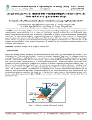
  • 1. International Research Journal of Engineering and Technology (IRJET) e-ISSN: 2395-0056 Volume: 05 Issue: 04 | Apr-2018 www.irjet.net p-ISSN: 2395-0072 © 2018, IRJET | Impact Factor value: 6.171 | ISO 9001:2008 Certified Journal | Page 138 Design and Analysis of Friction Stir Welding Using Dissimilar Alloys (AA 6061 and AA 6082) Aluminum Alloys Ravinder Reddy1, Abhishek tandle2, Sanne Srikanth3, Ramandeep Singh4 , Ramdeep kolli5 1Associate Professor, Dept. of Mechanical Engineering, VJIT college, Telangana, India 2345 Student, Dept. of Mechanical Engineering, VJIT college, Telangana, India --------------------------------------------------------------------------***---------------------------------------------------------------------------- Abstract: Friction stir welding (FSW) is a new solid-state joining process and this joining technique is energy efficient, versatile and environment friendly. Frequently it can be used to join high-strength aerospace aluminum alloys and other metallic alloys that are hard to weld by conventional fusion welding. FSW is considered to be the most significant development in metal joining in a decade. The scope of this investigation is to evaluate and experiment the effect of joining parameters on the mechanical properties of dissimilar aluminum alloys (AA 6082 and AA 6061 Aluminum Alloy) joints produced using friction stir welding. Friction stir weld was performed on the dissimilar aluminum alloys using different rotational speeds and traverse speeds and the influence of these parameters on the mechanical performance of the weld has been investigated in terms of hardness, tensile testing and statistical analysis. Key Words: Friction stir welding, RSM, Al Alloy 6061, Al Alloy 6082. 1. Introduction Friction stir welding (FSW) is a relatively new and promising solid state joining process developed and patented by The Welding Institute (TWI), Cambridge, U.K., Figure 1.1 shows the schematic drawing of FSW process. The work piece is placed on a backup plate and clamped rigidly by a fixture to prevent lateral movement during FSW. A specially designed frustum shaped tool with a pin extending from the shoulder is rotated with a speed of several hundred rpm and slowly pushed into the joining line. The pin usually has a diameter one-third of the shoulder and typically has a length slight less than the thickness of the work piece. The pin is forced into the work piece at the joint until the shoulder contact the surface of the work piece (figure 1.2 a). As the tool descends further, its surface friction with work piece creates more heat and later plasticizes a cylindrical metal column near the inserted pin and the immediate material under the shoulder. The weld usually thins the parent metal by about 3-6 % of original thickness. The work piece to be joined and the tool are moved are similar to each other such that the tool tracks along the weld interface and the rotating tool provides the ‘stir’ action. The plasticizing metal within a narrow zone moves while transporting metal from the leading face of the pin to the trailing edges. As the tool passes, the weld cools, thereby joining the two plates together (figure 1.2 b). On tool extraction a hole is left as the tool is withdrawn from the work piece (figure 1.2 c). Figure 1.1 Schematic drawing of friction stir welding
  • 2. International Research Journal of Engineering and Technology (IRJET) e-ISSN: 2395-0056 Volume: 05 Issue: 04 | Apr-2018 www.irjet.net p-ISSN: 2395-0072 © 2018, IRJET | Impact Factor value: 6.171 | ISO 9001:2008 Certified Journal | Page 139 Figure 1.2 Description of the three main stages of FSW (a) plunge phase (b) translational and rotational motion of the tool through the plates (c) tool extraction 2. Principle of friction stir welding The basic principal of Friction stir welding is heating the metal to a temperature below re-crystallization temperature using Friction generated by the cylindrical shouldered tool on metal. This tool having characteristic profile pin, which is rotated and pushed into the joint area between two pieces of sheet or the plate material. The parts have to be done secure clamping using the fixtures to prevent the joint faces from being forced apart. The Frictional heat is produced between the wear-resistant welding tool and the experimental work pieces, which causes the metals or alloys to soften without reaching the melting point. The tool moves along the joint line of the work materials. The plasticized material gets transferred to the moving edge of the tool pin and forced through similar contact with the tool shoulder and pin profile. The cooling of the material leads to the creation of a solid phase bond between the clamped work pieces. 3. Properties of material Aluminum Alloys AA 6082 and AA 6061 and process parameters The test plates of size 160 mm X 80 mm X 8 mm are prepared from aluminum alloy AA6082 plates using CNC cutting machine. The chemical composition and mechanical properties of the base material are presented in Table 1 and Table 2, respectively. 3.1 Chemical Composition Table 1. Chemical composition of aluminum alloy 6082 and 6061 Elements Mg Mn Fe Si Cu Cr Al 6061 1.1 0.12 0.35 0.58 0.22 0.04 Bal 6082 0.60- 1.20 0.40- 1.00 0.50 0.70- 1.30 0.10 0.25 95.2- 98.3 3.2 Physical Properties Table 2. Physical properties of aluminum alloy 6082 and 6061 Base metal Density(kg/m3) Melting temp ᵒC Modulus of elasticity GPa Poisson’s Ratio 6061 2700 580 69 0.33 6082 2710 555 69 0.33
  • 3. International Research Journal of Engineering and Technology (IRJET) e-ISSN: 2395-0056 Volume: 05 Issue: 04 | Apr-2018 www.irjet.net p-ISSN: 2395-0072 © 2018, IRJET | Impact Factor value: 6.171 | ISO 9001:2008 Certified Journal | Page 140 3.3 Mechanical Properties Table 3. Mechanical properties of aluminum alloy 6082 and 6061 Base Metal Yield stress, M pa Ultimate tensile strength, Mpa Hardness number, BHN Elongation % 6061 235 283 95 10-13 % 6082 250 140 to 330 95 10% 4. Welding Tool The welding tool of FSW plays a prominent role welding process which has an impact in the mechanical properties and quality of microstructure of the material. Therefore the tool is designed carefully which may alter the weld quality. The tool should have idealistic and higher mechanical properties than weld materials. The difficulties associated are mainly with finding proper tool material. The experiment is conducted using FSW machine shown in Fig. 1 to fabricate the joints. The welding was done by single pass. Fig 1. FSW machine Fig 2. Tool pin profile From the different tool materials like tool steel, carbon boron nitride, carbide, high carbon, high speed steel and high chromium steel (HCHCr). H13 is chosen as tool material because of its high strength, high hot hardness, easy to process, easily available and low cost. The FSW tools are manufactured using CNC Turning center and wire cut EDM machine. Fig 3 shows the tool designing and experimentation of the tool with the help of solid works auto desk. Fig 3. Tool designed using solid works software
  • 4. International Research Journal of Engineering and Technology (IRJET) e-ISSN: 2395-0056 Volume: 05 Issue: 04 | Apr-2018 www.irjet.net p-ISSN: 2395-0072 © 2018, IRJET | Impact Factor value: 6.171 | ISO 9001:2008 Certified Journal | Page 141 The friction stirring tool consists of a pin, or probe, and a shoulder. Contact of the pin with the work piece creates frictional and deformational heating and softens the work piece material; contacting the shoulder to the work piece increases the work piece heating, expands the zone of softened material, and constrains the deformed material. Fig 4. shows the most important tool parts. Fig 4. Tool pin and important parts Naturally, the important effects to the tool during welding are high temperature, abrasive wear and dynamic effects. Therefore, the good tool materials will be having the properties of good wear resistance, high temperature strength, temperature resistance, good toughness. 5. Plan of Investigation The follow a line of investigation work was to be carried out in the following steps: 1. Identifying the imperative process parameter. 2. Finding the upper and lower limits of the process parameter Viz. tool rotational speed (N), welding speed (S), and axial force (F) 3. Development of design matrix 4. Conducting the experiments as per the design matrix 5. Recording the responses, viz. Ultimate Tensile Strength (UTS), Yield Strength (YS), Percentage of Elongation (POE) 6. Development of the mathematical model 7. Checking the satisfactoriness of the models developed 8. Conducting the consistency test runs and comparing the results. 9. Presenting the special effects of the process parameters on the mechanical properties in graphical form and analyzing the results. 5.1 Important process parameter Based on initial trials, the independent process parameters affecting the mechanical properties were identified as: tool rotational speed (N), welding speed (S) and Tilt angle (T) 5.2 Finding the limits of control variable Test runs are conducted to find the upper and lower limit of process parameters, by varying one of the parameter and keeping the rest of them at constant values. The upper limit of a factor was coded as +2 and lower limit as -2. The intermediate coded values being calculated from the following relationship Xi=2 [2X-(Xmax+Xmin)]/(Xmax-Xmin) Shoulder Pin
  • 5. International Research Journal of Engineering and Technology (IRJET) e-ISSN: 2395-0056 Volume: 05 Issue: 04 | Apr-2018 www.irjet.net p-ISSN: 2395-0072 © 2018, IRJET | Impact Factor value: 6.171 | ISO 9001:2008 Certified Journal | Page 142 Where Xi is the required coded value of a variable X; and X is any value of the variable from Xmin to Xmax, Xmin is the lower limit of the variable and Xmax is the upper limit of the variable. The selected process parameters with their limits, units and notations are given in Table 4. Table 4 : Process parameter and its levels Std 1 2 3 4 5 6 7 8 9 Tool Speed 900 1120 1120 1120 1120 1120 1400 1400 1400 Feed rate 100 60 80 100 125 165 80 100 125 Degree 1.5 1.5 1.5 1.5 1.5 1.5 1.5 1.5 1.5 5.3 Development of Design Matrix The selected design matrix is shown in Table 5. It is a three factor five level central composite rotatable designs consisting of 20 sets of coded conditions composed of a full factorial 23 = 8, plus 6 centre points and 6 star points thus 20 experimental runs allowed the estimation of the linear, quadratic and two way interactive effects of the process parameter on the mechanical properties. 5.4. Conducting the experiment as per the design matrix The experiments were conducted as per the design matrix at random, to avoid the possibility of systematic errors infiltrating in to the system. 5.5 Recording of the responses Tensile test specimens are prepared as per ASTM E8 standard shown in Fig. 6 and transverse tensile properties such as ultimate tensile strength, yield strength, and percentage of elongation of the FS welded joints are evaluated using computerized UTM. For each welded plate, three specimens are prepared and tested. Fig. 5 shows tensile specimen after fracture of weld. The average values of the results obtained from those specimens are tabulated and presented in Table 5 Fig 5. Typical tensile specimen Fig 6. Tensile specimen after fracture
  • 6. International Research Journal of Engineering and Technology (IRJET) e-ISSN: 2395-0056 Volume: 05 Issue: 04 | Apr-2018 www.irjet.net p-ISSN: 2395-0072 © 2018, IRJET | Impact Factor value: 6.171 | ISO 9001:2008 Certified Journal | Page 143 Table 5: Estimated mechanical properties Std UTS N/mm2 Elongation % Yield Stress N/mm2 1 196.941 9.520 181.262 2 181.888 8.720 151.767 3 190.237 7.960 155.051 4 199.403 9.560 161.194 5 182.157 7.000 177.446 6 169.984 5.560 143.312 7 108.138 1.920 98.476 8 195.351 7.520 159.015 9 201.178 8.980 184.574 5.6 Development of mathematical model Ultimate tensile strength, yield strength, and percentage of elongation of the joints are functions of rotational speed, welding speed, and tilt angle and it can be expressed as Y = f (N, S, T) Where Y-The response N- Rotational speed, rpm S- Welding Speed, mm/s T–Tilt angle, degrees For the three factors, the selected polynomial (regression) could be expressed as UTS= 713.416 + -0.683336 * Tool Rotation + -1.69573 * Weld Feed + -0.00125722 * Tool Rotation * Weld Feed + 0.000305072 * Tool Rotation^2 + 0.0168008 * Weld Feed^2 YS= -69.434 + 0.134205 * Tool Rotation + 3.0318 * Weld Feed + -0.00423627 * Tool Rotation * Weld Feed + 0.000100582 * Tool Rotation^2 + 0.0130571 * Weld Feed^2 EL= 62.7155 + -0.0531229 * Tool Rotation + -0.414824 * Weld Feed + -4.7619e-05 * Tool Rotation * Weld Feed + 2.21365e-05 * Tool Rotation^2 + 0.00234346 * Weld Feed^2 The equation in terms of coded factors can be used to make predictions about the response for given levels of each factor. By default, the high levels of the factors are coded as +1 and the low levels are coded as -1. The coded equation is useful for identifying the relative impact of the factors by comparing the factor coefficients. DESIGN EXPERT 9 software packages are used to calculate the values of those coefficients for different responses and are presented in Table 5. After determining the coefficients, the mathematical models are developed.
  • 7. International Research Journal of Engineering and Technology (IRJET) e-ISSN: 2395-0056 Volume: 05 Issue: 04 | Apr-2018 www.irjet.net p-ISSN: 2395-0072 © 2018, IRJET | Impact Factor value: 6.171 | ISO 9001:2008 Certified Journal | Page 144 5.7 Developed final mathematical model The developed final mathematical model equations in the coded form are given below table 6 Regression Coefficient Ultimate tensile strength Yield stress Elongation A 295.61 339.73 0.7727 B 109.38 556.86 0.1263 AB 62.73 712.28 0.0900 A² 248.72 27.04 1.31 B² 503.25 303.96 9.79 UTS = 177.077 + -6.07871 * A + 3.69766 * B + -3.96025 * AB + 5.97941 * A^2 + 8.50541 * B^2 YS = 160.174 + -6.51657 * A + 8.34312 * B + -13.3442 * AB + 1.9714 * A^2 + 6.61015 * B^2 EL=7.87308 + -0.31079 * A + 0.125659 * B + -0.15 * AB 5.8 Checking the adequacy of the developed model The adequacy of the models so developed is then tested by using the analysis of variance technique (ANOVA). Using this technique, it is found that calculated F ratios are larger than the tabulated values at a 95% confidence level; hence, the models are considered to be adequate. Another criterion that is commonly used to illustrate the adequacy of a fitted regression model is the coefficient of determination (R2 ). For the models developed, the calculated R2 values and adjusted R2 values are above 70%. These values indicate that the regression models are quite adequate. The results of the ANOVA are given in Table 6. The validity of regression models developed is further tested by drawing scatter diagrams. Typical scatter diagrams for all the models are presented in Fig. 7-9. The observed values and predicted values of the responses are scattered close to the 45° line, indicating an almost perfect fit of the developed empirical models. Fig. 7: Scatter diagram of the ultimate Fig. 7: Scatter diagram of the yield stress Tensile strength, Mpa
  • 8. International Research Journal of Engineering and Technology (IRJET) e-ISSN: 2395-0056 Volume: 05 Issue: 04 | Apr-2018 www.irjet.net p-ISSN: 2395-0072 © 2018, IRJET | Impact Factor value: 6.171 | ISO 9001:2008 Certified Journal | Page 145 Fig. 9: Scatter diagram of the percentage of elongation. Table 7: ANOVA test results Response Sum of squares Degree of freedom Mean square F – value P - value Model Residual Model Residual Model Residual UTS 1921.53 5727.24 5 7 384.31 818.18 0.4697 0.7887 YS 1921.53 5727.24 5 7 384.31 818.18 0.4697 0.7887 EL 11.33 42.23 5 7 2.27 6.03 0.3757 0.8507 6. Analysis of the Results The effects of the different process parameter on the mechanical properties of FS welded aluminum alloy AA6082 and AA6061 are predicted from the mathematical models using the experimental interpretation are available in Figures 10showing the general trends between cause and effect. Effect of rotational speed (N) Fig. 10 shows the direct outcome of rotational speed on mechanical properties. It is seen that as the rotational speed increases the tensile strength, yield strength and percentage of elongation of FS welded aluminum alloy AA6082 and AA6061 increases and then it decreases. The highest rotational speed results in the metallurgical transformation such as solubilisation, re-precipitation, and coarsening of strengthening precipitates at the weld zone and lowering of dislocation density which decrease the tensile strength of the FS welded joints. It is clear that in FSW as the rotational speed increases the heat input also increases. More heat input destroys the regular flow behavior.
  • 9. International Research Journal of Engineering and Technology (IRJET) e-ISSN: 2395-0056 Volume: 05 Issue: 04 | Apr-2018 www.irjet.net p-ISSN: 2395-0072 © 2018, IRJET | Impact Factor value: 6.171 | ISO 9001:2008 Certified Journal | Page 146 Fig 10. Effect of tool rotation on properties Confirmation experiments Experiments are conducted to verify the regression equations of UTS, YS and EL. Nine weld runs are made using different values of rotational speed, welding speed and tilt angle other than what were used in the design matrix. The results obtained are quite satisfactory and the details are presented in Table 8 Table 8: Confirmation results Response Predicted mean Predicted Median Standard Deviation SE Prediction 95% PI Low 95% PI High UTS 177.077 177.077 30.5323 33.4465 97.9885 256.165 YS 160.174 160.174 28.6038 31.3339 86.0813 234.267 EL 6.876 6.876 2.45612 2.69055 0.513861 13.2381 7. Conclusions The following conclusions are arrived at from the above investigations. 1. The relations between process parameters for FS welding of AA6082 and AA6061 aluminum alloy have been established. The response surface methodology was adopted to develop the regression models, which were checked for their adequacy using ANOVA test, scatter diagrams and found to be satisfactory. 2. Confirmation tests have shown the development model is reasonably correct. 3. The increase in the tool rotational speed, welding speed and tilt angle to the increase in the ultimate tensile strength and it reaches a maximum value and then it decreases. This inclination is common for yield strength and percentage of elongation. References [1] R. Nandan, T. DebRoy and H. K. D. H. Bhadeshia, “Recent advances in friction stir welding–process, weldment structure and properties”, Progress in Materials Science, vol.53, 980-1023, (2008)
  • 10. International Research Journal of Engineering and Technology (IRJET) e-ISSN: 2395-0056 Volume: 05 Issue: 04 | Apr-2018 www.irjet.net p-ISSN: 2395-0072 © 2018, IRJET | Impact Factor value: 6.171 | ISO 9001:2008 Certified Journal | Page 147 [2] Jae-Hyung Cho, E. Donald, Boyce and Paul R. Dawson, “Modeling strain hardening and texture evolution in friction stir welding of stainless steel”, Material Science Engineering A, 398, 146-163. (2005). [3] C. J. Dawes and W. M. Thomas, “Friction stir process welds aluminum alloys”, Welding Journal 75, 41-44, (1996). [4]H. Uzun, C.D. Donne, A. Argagnotto, T. Ghidini and C. Gambaro, “Friction stir welding of dissimilar Al 6013-T4 to X5CrNi18- 10 stainless steel”, Materials and Design, 26, 41- 46, (2005). [5] L. Litynska, R. Braun, G. Staniek, C. Dalle Donne and J. Dutkiewicz, “TEM study of the microstructure evolution in a friction stir-elded Al Cu Mg Ag alloy”, Materials Chemistry and Physics, 81, 293-295, (2003). [6] K. Elangovan and V. Balasubramanian, “Influences of tool pin profile and tool shoulder diameter on the formation of friction stir processing zone in AA6061 aluminum alloy”, Material and Design, 29, 362-373, (2008). [7] M. St. Weglowskib, Y. Huang and Y. M. Zhang, “Effect of welding current on metal transfer in GMAW”, Archives of Materials Science and Engineering, 33, 49-53, (2008). [8] D. T. Thao, J. W. Jeong, I. S. Kim and J. W. H. J. Kim, “Predicting Lap- Joint bead geometry in GMA welding process”, Archives of Materials Science and Engineering, 32, 121-124, (2008). [9] H. D. Chandler and J. V. Bee, “Cyclic strain induced precipitation in a solution treated aluminum alloy”, Act Metallurgical, 35, 2503-2510, (1987). [10] S. Lomolino, R. Tovo and J. Dos Santos, “On the fatigue behavior and design curves of friction stir butt welded Al alloys”, International Journal of Fatigue, 27, 305-316, (2005). [11] V. Gunaraj and N. Murugan, “Application of response surface methodology for prediction weld bead quality in submerged arc welding of pipes”, Journal of Material Processing Technology, 88, 266-275, (1999). [12] K. Elangovan, V. Balasubramanian and S. Babu, “Predicting tensile strength of friction stir welded 6061 aluminum alloy joints by mathematical model”, Material and design, 30, 188-193, (2009). [13] J. Colligan, J. Paul, Konkol, J. James, Fisher and R. Pickens Joseph, “Friction stir welding demonstrated for combat vehicle construction”, WeldingJournal, 1-6, (2003). [14] R. Palanivel, P. Koshy Mathews and N. Murugan. “Development of mathematical model to predict the mechanical properties of friction stir welded AA6351 aluminum alloy”, Journal of Engineering Science and Technology Review 4 (1) (2001)25-31. [15] Pierpaolo Carlone and Gaetano S. Palazzo, “Longitudinal Residual Stress Analysis in AA2024-T3 Friction Stir Welding”. The Open Mechanical Engineering Journal, 2013, 7, 18-26.