Analytical Investigation and Comparison on Performance of Ss316, Ss440c and Titanium Alloy Tool Materials Used As Single Point Cutting Tool
•
0 likes•202 views

Theoretical analysis for performance studies of SS316, SS44OC and Titanium Alloy used as a cutting tool is presented in this paper. Tool temperature, tools wear and life of the tool is investigated analytically. These theoretical values are compared with the experimental studies conducted by the author. The values obtained from experimental studies are comparable with analytical values and variation is the correlation between theoretical and experimental values is of the order of 15%.

Recommended
Recommended
More Related Content
What's hot
What's hot (19)
Viewers also liked
Viewers also liked (9)
Similar to Analytical Investigation and Comparison on Performance of Ss316, Ss440c and Titanium Alloy Tool Materials Used As Single Point Cutting Tool
Similar to Analytical Investigation and Comparison on Performance of Ss316, Ss440c and Titanium Alloy Tool Materials Used As Single Point Cutting Tool (20)
Recently uploaded
Recently uploaded (20)
Analytical Investigation and Comparison on Performance of Ss316, Ss440c and Titanium Alloy Tool Materials Used As Single Point Cutting Tool
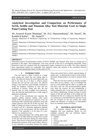
- 1. Mr. Amaresh Kumar D et al. Int. Journal of Engineering Research and Applications www.ijera.com ISSN: 2248-9622, Vol. 5, Issue 8, (Part - 1) August 2015, pp.55-61 www.ijera.com 55 | P a g e Analytical Investigation and Comparison on Performance of Ss316, Ss440c and Titanium Alloy Tool Materials Used As Single Point Cutting Tool Mr. Amaresh Kumar Dhadange1 , Dr. H.G. Hanumantharaju2 , Mr. Suresh3 , Mr. Karthik K Kallur4 , Mr. Anand S5 1 (Faculty, Department of Mechanical Engineering, Sri Venkateshwara College of Engineering, Bangalore- 562157) 2 (Faculty, Department of Mechanical Engineering, University Visvesvaraya College of Engineering, Bangalore- 560001) 3 (Faculty, Department of Mechanical Engineering, Sri Venkateshwara College of Engineering, Bangalore- 562157) 4 (Student, Department of Mechanical Engineering, University Visvesvaraya College of Engineering, Bangalore- 560001) 5 (Student, Department of Mechanical Engineering, University Visvesvaraya College of Engineering, Bangalore- 560001) ABSTRACT Theoretical analysis for performance studies of SS316, SS44OC and Titanium Alloy used as a cutting tool is presented in this paper. Tool temperature, tools wear and life of the tool is investigated analytically. These theoretical values are compared with the experimental studies conducted by the author. The values obtained from experimental studies are comparable with analytical values and variation is the correlation between theoretical and experimental values is of the order of 15%. I. INTRODUCTION The tool used in a lathe is known as a single point cutting tool which has one cutting edge or point. The lathe tool shears the metal rather than cuts and it can only do so if there is relative motion between the tool and the work piece. For efficient cutting, a tool must have good strength, resistance to shock, hot hardness, resistance to wear and low coefficient of friction. Along with this, the tool material must be easily available and economical. Also, the materials used should have a wider range of application, preferably. Some of the conventional tool materials like tungsten carbide, titanium carbide, cubic boron nitride (CBN) and diamond are expensive. Even for machining softer materials like aluminium, brass and copper expensive tools like TiC & WC are used. The range of cutting tool types is extensive. The selection of correct tool for a particular application depends especially on the tool geometry and the cutting tool material, if the operation is to be done in a cost- effective (i.e. productive) way. The cutting parameters like cutting speed, feed and depth of cut affect different cutting forces exerted on the tool and work piece during any metal cutting action. These forces in turn derive the quality and the dimensional accuracies of the metal surface. Hence it is very important to accurately measure the cutting forces and control them to obtain required degree of surface and / or dimensional accuracy on the surface, Electronic Dynamometers are used to measure these forces. When the tool wear reaches an initially accepted level, there are two options - one is to resharpen the tool on a tool grinder and the other is to replace the tool with a new one. This second possibility applies only when the resource for tool resharpening is totally exhausted and / or the tool does not allow for any further resharpening. Gradual wearing of certain regions of the face and flank of the cutting tool can terminate the life of a cutting tool, therefore the life of a cutting tool is determined by the amount of wear that has occurred on the tool profile and which reduces the efficiency of cutting to an unacceptable level, or eventually causes tool failure. II. MATERIAL SELECTION Tool materials selected based on hardness, toughness and wear properties. Below are few candidate materials that can substitute today’s expensive tool material. SS440C SS316 Titanium alloy (G5) Inconel Ferritic stainless steel 1.4003 RESEARCH ARTICLE OPEN ACCESS
- 2. Mr. Amaresh Kumar D et al. Int. Journal of Engineering Research and Applications www.ijera.com ISSN: 2248-9622, Vol. 5, Issue 8, (Part - 1) August 2015, pp.55-61 www.ijera.com 56 | P a g e Invar 3 Among the above materials, the materials selected for our experimentations are SS440C, SS316 and Titanium alloy (G5) on the basis of required mechanical properties for the present work. The single point cutting tools are prepared according to the standard by using HSS tool as reference. Fig1 represent the final cutting tools obtained. The work piece materials used are as follows; a. Mild Steel (for HSS and SS440C) b. Aluminium (for SS316 and Titanium alloy) Figure1. Test Specimens After the preparations of the cutting tool, heat treatment processes were carried out for improving the hardness property of the material. III. EXPERIMENTATION Once the cutting tool is fabricated the next step is to subject these tools to various standard tests to determine the tool performance for the intended application on the tool samples which has been clearly discussed in the first paper “Investigation on SS316, SS440C and Titanium Alloy Grade-5 used as Single Point Cutting Tool” FEAANALYSIS Ansys is a leading finite element tool used for mechanical design applications. In metal cutting Ansys can be used as a FEA tool for our purpose. Metal cutting can be considered as a large deformation transient analysis /explicit analysis for the analysis. Because explicit analysis will give better result in such conditions our project work metal cutting is done in ANSYS explicit analysis. Using ANSYS as preprocessor geometrical FE model was created assuming the rake angle 7º, clearance angle 14º and edge radius 3º. Boundary conditions of the FE model were as fallowed. The work piece was constrained in all 6 DOF, load of the type U=f (t) (Displacement according to time) with the purpose of simulate cutting motion with respect to the cutting velocity. The FEA geometric model constrained 35060 nodes &31240 elements. For structural SOLID187 element were chosen as they are used in explicit analysis assuming large deformation speed and non- linear contact for composition of geometric model. Work piece mesh sensitively study was performed. For thermal analysis SOLID187 element were chosen as they are used in the thermal analysis. Couple field type transient analysis was done for the temperature distribution. With the help of temperature distribution and wear analysis theory we can find wear rate of the material. The wear rate of the material will directly influences the tool life of the investigated tool material. For selection and specification dynamic constants by FEM the problem is interaction of deformable body and rigid body. Deformable body is work piece and defined as slave for contact search and chip separation in numerical analysis. A turning tool is a rigid body. Assuming tool dynamics and defined as a master for contact search in explicit numerical analysis. A. INITIAL CHIP FORMATION: By considering the cutting tool as a rigid model and work piece as a flexible material, boundary condition is applied for the tool-work piece arrangement. Feed is given for the tool and work piece is fixed with all degrees of freedom. Total load is divided to load steps for better convergence. At initial load steps tool will hit the work piece and it starts to cut the metal stress is recorded and stress variation is plotted. B. CHIP GROWTH ANALYSIS: As cutting tool advances cutting the stress distribution also varies and results are plotted for the same. Mechanical work done observed and simulation is done for the complete cycle. Max stress occurred during cutting is plotted. Total mechanical work done is transferred to the heat and this heat generation is considered for the thermal analysis input. Transient thermal heat analysis is done in ANSYS APDL for the temperature distribution and results are plotted. Fig 1: Tool Mesh Profile
- 3. Mr. Amaresh Kumar D et al. Int. Journal of Engineering Research and Applications www.ijera.com ISSN: 2248-9622, Vol. 5, Issue 8, (Part - 1) August 2015, pp.55-61 www.ijera.com 57 | P a g e Fig 2: Tool and work piece solid model Fig 3: Tool and work piece mesh model c. MANUFACTURING SIMULATION BY FEA I) TOOL: HSS WORK PIECE: MILD STEEL (EN19) Fig 4: HSS Tool initial chip formation Fig 5 : HSS Tool initial chip growth formation Fig 6: HSS Tool chip total deformation Fig 7: HSS Tool normal stress Fig 8: HSS Tool shear stress II) Tool: SS440C Work piece: Mild Steel (EN19) Fig 9: SS440C Initial Chip
- 4. Mr. Amaresh Kumar D et al. Int. Journal of Engineering Research and Applications www.ijera.com ISSN: 2248-9622, Vol. 5, Issue 8, (Part - 1) August 2015, pp.55-61 www.ijera.com 58 | P a g e Fig 10: SS440C Tool Chip Growth Fig 11: SS440C Tool Total Deform Chip Fig 12: SS440C Tool Normal Stress Distribution Fig 13: SS440C Tool Shear Stress Distribution III): TOOL: SS316 WORK PIECE: ALUMINIUM Fig.14:SS316 Tool with Initial Chip Formation Fig. 15:SS316 Tool with Chip Growth Fig.16:SS316 Tool with Total Chip Formation Fig.17:SS316 Tool Normal Stress Distribution
- 5. Mr. Amaresh Kumar D et al. Int. Journal of Engineering Research and Applications www.ijera.com ISSN: 2248-9622, Vol. 5, Issue 8, (Part - 1) August 2015, pp.55-61 www.ijera.com 59 | P a g e Fig.18:SS316 Tool Shear Stress Distribution IV): TOOL: TITANIUM ALLOY WORK PIECE: ALUMINIUM Fig.19: Titanium Alloy Tool with Initial Chip Fig.20: Titanium Alloy Tool with Chip Growth Fig. 21: Titanium Alloy Tool with Total Chip Formation Fig.22: Titanium Alloy Tool Normal Stress Distribution Fig.23: Titanium Alloy Tool Shear Stress Distribution V): TEMPARATURE DISTRIBUTION Fig.24: HSS tool temperature distribution Fig.25: SS440C tool temperature distribution
- 6. Mr. Amaresh Kumar D et al. Int. Journal of Engineering Research and Applications www.ijera.com ISSN: 2248-9622, Vol. 5, Issue 8, (Part - 1) August 2015, pp.55-61 www.ijera.com 60 | P a g e Fig.26: SS316 tool temperature distribution Fig.27: TITANIUM ALLOY tool temperature distribution IV. WEAR ANALYSIS TABLE: TOOL MATERIAL WEAR DETAILS MATERIALS EXPERIMENT AL IN µm/min ANALYTICA L IN µm/min HSS TOOL 126 168 SS440C TOOL 135 103 SS316 TOOL 108 108 TITANIUM ALLOY 135 108 Graph 6.10.HSS Tool V/S.SS440C Tool Graph 6.11.SS316 Tool V/s. Titanium Alloy V. RESULT AND DISCUSSIONS The tool life of the selected cutting tools decreases with increase in cutting speed as shown in the Graph Nos. 6.6 to 6.9. Good surface finish was obtained for aluminium and MS work piece when machined with respective cutting tools at high cutting speeds which slightly reduces tool life. Due to hardening process carried out on respective tools, they can withstand mechanical vibrations at high speeds. Heat generated between tool-work piece interface results in change in grain structure of the tool tip zone. At high temperature the material removed gets fused to the tool tip and thus results in poor surface finish. In order to remove the heat generated at tool tip the cutting fluids are used. By providing proper coatings the heat generated can be reduced and thus the tool life can be improved. VI. CONCLUSIONS 1. For mild steel work piece material, SS440C materials were found to be cost effective, compared HSS material. 2. For aluminium work piece material, SS316 were found to be cost effective as compared to Titanium alloy(Ti-6Al-4V) 3. For mild steel work piece material, at low cutting speed the Shear force of the SS440C material is high as compared to the HSS tool. 4. For aluminium work piece material, at lower cutting speed SS316 has a greater Shear force than the Titanium alloy (Ti-6Al-4V), but at higher cutting speeds Titanium alloy (Ti-6Al-4V) were found to have higher Shear force than SS316. 5. For mild steel work piece material, at all cutting speeds tool life of HSS and SS440C were found to be relatively close. 6. For aluminium work piece material, at all speeds Titanium alloy (Ti-6Al-4V) were found to be having longer tool life than SS316. 7. SS440C tool can be replaced with HSS tool for mild steel work piece. 0 50 100 150 200 HSS TOOL SS440C TOOL WEARRATEINµm/min. TOOL MATERIALS HSS V/s. SS440C EXPERIMENTAL ANALYTICAL 0 20 40 60 80 100 120 140 160 SS316 TOOL TITANIUM ALLOY WEARRATEINµm/min TOOL MATERIALS SS316 V/s. TITANIUM ALLOY EXPERIMENTAL ANALYTICAL
- 7. Mr. Amaresh Kumar D et al. Int. Journal of Engineering Research and Applications www.ijera.com ISSN: 2248-9622, Vol. 5, Issue 8, (Part - 1) August 2015, pp.55-61 www.ijera.com 61 | P a g e 8. Instead of adopting high cost carbide tip tool for machining of soft materials like aluminum can be avoided by using SS316. 9. SS316 will produce low surface finish rather than the titanium alloy material. 10. Diffusion of material has occurred and deposited over the flank and creator on titanium alpha material deposited more on the rake face especially on the creator. This was due to high heat concentration by chips. This acted like shield &reduces further creator formation. VII. SCOPE FOR FUTURE WORK: 1. Based on the materials survey this work concluded that, only martensitic stage materials are suitable for cutting tools. 2. Adopting different heat treatment process to further increase the hardness of the materials. 3. Adopting multiple coatings methods to reduce flank wear and increase tool life. 4. By changing the rake angles values how it influences on machining parameters. 5. By experimenting different stainless steel grades (SS grades) and adopting suitable heat treatment processes the results are compared. REFERENCES [1.] Mr.Kothakota Suresh Kumar, Mr. Amaresh Kumar, Dr.H.G.Hanumantharaju, Mr.Monish G, Mr.Sridhar S M, Investigation on SS316, SS440C, and Titanium Alloy Grade-5 used as Single Point Cutting Tool, Int. Journal of Engineering Research and Application, ISSN : 2248-9622, Vol. 5, Issue 1. [2.] Dr. Viktor P. Astakhov, Tool Geometry: Basic Fuzzing modelling of a single point lathe cutting tool. R. Marumo, M. T. Letsatsi and O. S. Motsamai: Journal of Mechanical Engineering Research. Vol. 3(7), pp. 264–288, July 2011; ISSN: 2141 - 2383 ©2011 [3.] Arshinov V. and Alekseev G. (1976), Metal Cutting Theory and Cutting Tool Design, Chapter 7: Mir Publishers, Moscow 4.” Life enhancement of single point cutting tool by hard Facing and cryogenic treatment” [4.] Hazoor S. Sidhu A, Kumar Gauravb, Rakesh Bhatiaa National Conference on Advancements and Futuristic Trends in Mechanical and Materials Engineering (February 19-20, 2010) [5.] David. T. Reid Fundamentals of Tool Design 3rd edition chapter 1. [6.] P Kulandaivelu1, 2, P Senthil Kumar3 and S Sundaram2, 4, Wear monitoring of single point cutting tool using acoustic emission techniques MS received 13 April 2009; revised 28 August 2011; accepted 3 FEBRUARY 2012 publication: Sadhana Vol. 38, Part 2, April 2013, pp. 211–234._c Indian Academy of Sciences [7.] Pradeep Kumar Patil, A.I. Khandwawala” analytical investigation of the cutting forces on single point cutting tool” new coating developments for high performance cutting tools [8.] E. Uhlmann1, E.Wiemann, S. Yang, J. Krumeich, A. Layyous 9. Noemia Gomes de Mattos de Mesquita, José Eduardo Ferreira de Oliveira, Arimatea Quaresma Ferraz, “Life Prediction of Cutting Tool by the Workpiece Cutting Condition “Advanced Materials Research Vol. 223 (2011) pp 554- 563 © (2011) Trans Tech Publications, Switzerland doi:10.4028/www.scientific.net/AMR.223.5 54 [9.] M.J. Jackson a,*, G.M. Robinson b, J.S. Morrell b Machining M42 tool steel using nano structured coated cutting tools received 03.04.2007; published in revised form 01.07.2007