SlideShare a Scribd company logo
1 of 8
Download to read offline
INTERNATIONAL RESEARCH JOURNAL OF ENGINEERING AND TECHNOLOGY (IRJET) E-ISSN: A2395-0056
VOLUME: 09 ISSUE: 02 | FEB 2022 WWW.IRJET.NET P-ISSN: 2395-0072
© 2022, IRJET | Impact Factor value: 7.529 | ISO 9001:2008 Certified Journal | Page 365
Decoding DMA Transactions and Implementing VFIO in USB4
Rajat Khandelwal
Intel Technology India Pvt. Ltd., Bengaluru, India
----------------------------------------------------------------------***---------------------------------------------------------------------
Abstract—USB4 as a connectivity standard was developed
to converge the USB Type-C connector ecosystem along
with ultra-high speeds. The typical speed of data transfer
over one USB4 transmission line is 20 Gbps making it a
total bandwidth of 40 Gbps over two transmission lines.
USB4 replaces USB3.2 while retaining USB2.0 bus
operating in parallel. A variety of protocols are tunneled
over USB4 routers, which include DP/HDMI, USB3 and
PCIe. There are various interface adapters distributed
throughout a USB4 router, which house address spaces. It’s
evident that all the address space cannot be addressed
using memory BARs which calls for another method of
data transmission – DMA. The various types of interface
adapters are addressed in this paper along with the types
of address spaces which the routers encompass. The only
memory which is mapped directly through memory BARs
is the host interface address space. This address space
consists of four important sections – Host interface control,
transmit descriptor rings, receive descriptor rings, and
interrupt control. The memory addressed by BARs resides
typically in BAR0, which is why it is possible to map this
memory to user space using VFIO mechanism. A short
introduction to user space mapping via VFIO is also
provided in the paper.
Keywords—USB4 specification, Control channels, DMA,
Configuration spaces, USB4 adapters, VFIO
I. INTRODUCTION
We have come a long way from data speeds ranging
from 12 Mbps (USB1.1) to 20 Gbps (USB3.2). This dramatic
shift of speed advances has only been possible by
increasing throughput and the arrival of Type C subsystem
which provided a common high-speed interface for the
protocols.
Thunderbolt and USB4 are two technologies which uses
dual speed lanes for data transfer and their speed caps at
40 Gbps (20 Gbps per lane). Both the technologies use
standard Type C interface. The important thing to note is
that TBT and USB4 are themselves not protocols, but ways
to tunnel various protocols. Below is a representation of the
difference in speeds of various interfaces and the protocols
tunneled by them.
USB spec Max speed PHY Type Connectors
supported
USB1.1 12 Mbps Full Speed Type A
USB2.0 480 Mbps High speed Type A
USB3.1
Gen1 (1x1)
5 Gbps Super Speed Type A/C
USB3.1
Gen2 (2x1)
10 Gbps Super Speed
Plus
Type A/C
USB3.2
(2x2)
20 Gbps Super Speed
Plus
Type C
TBT3 x1 20.625
Gbps
CIO Type C
TBT3 x2 41.25 Gbps CIO Type C
USB4 x1 20 Gbps CIO Type C
USB4 x2 40 Gbps CIO Type C
An interesting thing to note is that TBT3 tunnels PCIe
and DP/HDMI protocols but not USB3. But USB4 tunnels all
these 3 protocols. USB2 protocol still exists in modern Type
C connectors as a legacy mechanism of data transfer and is
not tunneled. Separate D+/D- channels run through Type C
connector to support USB2 single lane protocol.
The supporting mechanism through which USB4 work is
by tunneling the protocols through routers. The router
which is present in the host is termed as host router.
Similarly, we have device routers which can be connected in
the form of daisy chain subsequently. Below is a figure
which represents USB4 gatkex card supplied by Intel.
Fig. 1. USB4 gatkex card (Intel generic)
The USB4 gatkex card shown above is basically a USB4
device router from within. The above figure has 3
downstream Type C ports and 1 upstream Type C port. The
upstream port can be connected to a host Type C receptacle
through a thunderbolt cable.
We will see how a router is laid out in a USB4
specification. Each router has 3 adapters – Protocol
adapters, Control adapters, and Lane adapters. Each router
has its own router configuration space. The protocol and
lane adapters have adapter, path and counters
configuration spaces. Point to note is that there are two
lane adapters in each router since there are two lanes each
providing a throughput of 20 Gbps.
INTERNATIONAL RESEARCH JOURNAL OF ENGINEERING AND TECHNOLOGY (IRJET) E-ISSN: A2395-0056
VOLUME: 09 ISSUE: 02 | FEB 2022 WWW.IRJET.NET P-ISSN: 2395-0072
© 2022, IRJET | Impact Factor value: 7.529 | ISO 9001:2008 Certified Journal | Page 366
The protocol adapters are subdivided into upstream and
downstream protocol adapters which are specific to USB3,
PCIe and DP/HDMI. They are basically used to convert
USB4 traffic into protocol traffic and vice versa.
There exists a host interface adapter which is present in
the host interface layer. This layer houses N transmit
descriptor rings and N receive descriptor rings. The
transmit ring and receive ring with hop ID 0 is used to
communicate between host (connection manager) and the
USB4 domain.
This host interface layer houses certain registers which
are mapped via memory PCIe BARs. The configuration
spaces however are large and thus can only be addressed
through DMA. This paper primarily focuses on how the
DMA transactions take place and what they are made of.
Further we will see how can we map the host interface
layer to user space via VFIO.
II. LAYOUT OF A ROUTER
A USB4 router can be theoretically represented in the
form given below.
Fig. 2. Representation of a USB4 router
This router contains two downstream USB4 Type C
ports and one upstream port. As we can see, there are PCIe
upstream and PCIe downstream adapters corresponding to
the direction of the data flow. Similarly, we have USB3
upstream and downstream adapters. There is also a time
management unit (TMU) which supports time
synchronization within routers.
As represented in the figure, USB2 lanes run separately
through a channel which is called D+/D- channel in Type C
receptacle.
III.ADAPTERS AND CONFIG SPACES
There are three types of adapters in a USB4 router –
Protocol adapters, Control adapters and Lane adapters. We
have two types of protocol adapters – Host interface
adapter and generic protocol adapters
(USB3/DP/HDMI/PCIe). All the adapters except control
adapters house configuration spaces – Adapter config
space, Path config space and Counter config space. In
addition, each router also has its own router config space
and a sideband (SB) register space which is addressed
through SBU transactions.
As explained earlier, the registers residing in host
interface layer can be easily addressed using memory
BAR0. And thus, they can be easily ported to user space
using VFIO. The configuration spaces can only be addressed
using DMA.
The figure given below represents various layers and
adapters in a USB4 router.
Fig. 3. USB4 adapters across functional layers
IV.TRANSPORT LAYER
All the packets on arriving a router are directed toward
transport layer. Following is the direction flow of all the
packets that are present as a part of USB4 transaction.
A. Control packets: A read/write control packet can
be transmitted from host to a router and from a
router to a host. When the flow direction is from
host to router, the packet is transmitted from host
to host interface adapter, then it goes to control
adapter, then to the transport layer and then to the
respective configuration space. Similarly a control
packet received from a router’s configuration
space is transmitted from configuration space to
transport layer to control adapter to host interface
layer to lane adapter to finally host.
B. USB3 packets: For the USB3 packets going from
USB3 host to router, the transmission flow is USB3
host to USB3 interface adapter to control adapter
to transport layer to respective adapter.
C. PCIe packets: PCIe packets are transmitted from a
PCIe end point to a PCIe bridge (if exists) to PCIe
interface adapter to control adapter to transport
layer to respective adapter.
D. DP/HDMI packets: DP/HDMI packets are direct
flow packets. They have a source and destination.
They originate from a DP/HDMI source and are
transmitted to DP/HDMI interface adapter to
control adapter to transport layer to respective
adapter.
INTERNATIONAL RESEARCH JOURNAL OF ENGINEERING AND TECHNOLOGY (IRJET) E-ISSN: A2395-0056
VOLUME: 09 ISSUE: 02 | FEB 2022 WWW.IRJET.NET P-ISSN: 2395-0072
© 2022, IRJET | Impact Factor value: 7.529 | ISO 9001:2008 Certified Journal | Page 367
E. Link type transactions: These originate from
logical layer and are used during lane initialization.
They are also used to signal a change in adapter
state due to events such as a lane disconnect or
transition to a low power state. LT transactions are
transmitted from logical layer to control adapter to
transport layer to SB (sideband) channel to SB
channel of another router to control adapter to
transport layer to respective SB register space.
F. Administrative type transactions: AT transactions
are used at the time of router enumeration and
they serve the purpose of identifying lanes,
generation and speed in a router. They have the
same route as that of link type transactions. These
are also SB transactions and are transmitted along
the SBU lines.
G. Broadcast retimer type transactions: BRT
transactions are also SB transactions which are
transmitted to enumerate retimers. There can be a
maximum of 6 retimers between two routers. Thus
retimer numbering can go from 1 to maximum of 6.
BRT transactions occur in both directions from
router A to router B and vice versa. They have the
same path as that of LT transactions.
H. Addressed retimer transactions: ART transactions
are solely used for TxFFE negotiations. There exists
a TxFFE register in SB register space of each
router. ART transactions follow the same route as
that of LT transactions.
V. TIME SYNCHRONIZATION
The Time Synchronization Protocol is a distributed
protocol that defines how the real-time clocks in a USB4
fabric synchronize with each other. The real-time clocks are
organized into a hierarchy with the host router at the top of
the hierarchy determining the reference time for the entire
domain. Clock synchronization is achieved by exchanging
ordered sets and time sync packets where downstream
devices use both local timestamps and the timing
information in the time sync Packets to adjust their clocks
to the time of the host router.
When Inter-Domain time synchronization is disabled,
the time synchronization protocol executes within the
scope of a single domain. All time sync packets, state
machines and other entities are associated with a single
domain. The time established within one domain by the
protocol is independent of the time in other domains.
When Inter-Domain time synchronization is enabled,
the time synchronization protocol executes within the
scope of an interconnected set of domains. The Connection
Manager s of the domain establish an Inter-Domain clock
synchronization hierarchy by selecting one of the host
routers to be the time source for all domains. The time
synchronization protocol then synchronizes the clocks of
the other domains to the Inter-Domain host router clock.
[3]
VI.LANE ADAPTER STATE MACHINE
The state machine in the given figure describes the
behavior of the logical layer in a lane adapter. A detailed
description of the states and transitions between states
follows.
A. Disabled state: The lane adapter disables the lane.
B. CLd state: Lane adapter transmitter and receiver
are inactive.
C. Training state: The lane adapter performs symbol
synchronization and transfer of lane parameters.
D. CL0 state: The lane adapter can transmit and
receive transport layer packets across the lane.
E. Lane bonding state: bonds two single lane links
into a dual lane link.
F. CL0s, CL1 and CL2 state: Low power states. [3]
VII. ROUTER CONFIGURATION SPACE
The following configuration registers are present in
router config space.
Register name Bit(s) Field name
ROUTER_CS_0 15:0 Vendor ID
31:16 Device ID
ROUTER_CS_1 7:0 Next
capability
pointer
13:8 Upstream
adapter
19:14 Max adapter
22:20 Depth
ROUTER_CS_2 23 Rsvd
INTERNATIONAL RESEARCH JOURNAL OF ENGINEERING AND TECHNOLOGY (IRJET) E-ISSN: A2395-0056
VOLUME: 09 ISSUE: 02 | FEB 2022 WWW.IRJET.NET P-ISSN: 2395-0072
© 2022, IRJET | Impact Factor value: 7.529 | ISO 9001:2008 Certified Journal | Page 368
31:24 Revision
number
ROUTER_CS_3 31:0 Topology ID
low
ROUTER_CS_4 23:0 Topology ID
high
30:24 Rsvd
31 Topology ID
valid
ROUTER_CS_5 7:0 Notification
timeout
15:8 CM USB4
version
23:16 Rsvd
31:24 USB4 version
ROUTER_CS_6 0 Enter sleep
1 Enable wake
on PCIe
2 WO USB3
3 Enable wake
on DP
22:4 Rsvd
23 CM TBT3
support
24 PCIe
tunneling ON
25 USB3
tunneling ON
26 Internal host
controller ON
30:27 Rsvd
31 Configuration
valid
ROUTER_CS_7 0 Sleep ready
1 TBT3 not
supported
2 Wake on
PCIe status
3 Wake on
USB3 status
4 Wake on DP
status
17:5 Rsvd
18 Internal host
controller
implemented
23:19 Rsvd
24 Router ready
25 Config ready
31:26 Rsvd
ROUTER_CS_8 31:0 UUID high
ROUTER_CS_9 31:0 UUID low
ROUTER_CS_10 31:0 Data[0]
ROUTER_CS_11 31:0 Data[1]
ROUTER_CS_12 31:0 Data[2]
ROUTER_CS_13 31:0 Data[3]
ROUTER_CS_14 31:0 Data[4]
ROUTER_CS_15 31:0 Data[5]
ROUTER_CS_16 31:0 Data[6]
ROUTER_CS_17 31:0 Data[7]
ROUTER_CS_18 31:0 Data[8]
ROUTER_CS_19 31:0 Data[9]
ROUTER_CS_20 31:0 Data[10]
ROUTER_CS_21 31:0 Data[11]
ROUTER_CS_22 31:0 Data[12]
ROUTER_CS_23 31:0 Data[13]
ROUTER_CS_24 31:0 Data[14]
ROUTER_CS_25 31:0 Data[15]
ROUTER_CS_26 31:0 Metadata
ROUTER_CS_27 15:0 Opcode
23:16 Rsvd
29:24 Status
30 Operation
not
supported
31 Operation
valid
The above table is provided to give a representation of
what a router config space looks like.
VIII.ADAPTER CONFIGURATION SPACE
Every adapter (except for a control adapter) shall have
its own adapter configuration space. The adapter
configuration space structure begins with a set of
doublewords describing the basic attributes of an adapter.
The rest of the space is populated with a linked list of
capabilities.
A Connection Manager reads from or writes to adapter
configuration space using the read requests and write
requests defined. A router shall allow a Connection
Manager to access adapter configuration space regardless
of whether or not the adapter is connected.[3]
IX.USB4 HOST MEMORY
The host interface layer of a USB4 router houses these
registers:
Offset Register name
Host interface control
39640h Host interface capabilities
39858h Host interface reset
39864h Host interface control
39880h Host interface CL1 enable
39884h Host interface CL2 enable
Transmit descriptor rings
00000h + n*10h Base address low
00004h + n*10h Base address high
00008h + n*10h Producer and consumer
INTERNATIONAL RESEARCH JOURNAL OF ENGINEERING AND TECHNOLOGY (IRJET) E-ISSN: A2395-0056
VOLUME: 09 ISSUE: 02 | FEB 2022 WWW.IRJET.NET P-ISSN: 2395-0072
© 2022, IRJET | Impact Factor value: 7.529 | ISO 9001:2008 Certified Journal | Page 369
indexes
0000Ch + n*10h Ring size
19800h + n*20h Ring control
Receive descriptor rings
08000h + n*10h Base address low
08004h + n*10h Base address high
08008h + n*10h Producer and consumer
indexes
0800Ch + n*10h Ring and buffer size
29800h + n*20h Ring control
29804h + n*20h PDF bit masks
Interrupts
37800h : 37800h + (4 *
ceiling(3N/32) – 1)
Interrupt status (ISR)
37808h : 37808h + (4 *
ceiling(3N/32) – 1)
Interrupt status clear (ISC)
37810h : 37810h + (4 *
ceiling(3N/32) – 1)
Interrupt status set (ISS)
38200h : 38200h + (4 *
ceiling(3N/32) – 1)
Interrupt mask (IMR)
38208h : 38208h + (4 *
ceiling(3N/32) – 1)
Interrupt mask clear (IMC)
38210h : 38210h + (4 *
ceiling(3N/32) – 1) I
Interrupt mask set (IMS)
38C00h : 38C3Ch Interrupt throttling rate
(ITR)
38C40h : 38C40h + (4 *
ceiling(3N/8) – 1)
Interrupt vector allocation
(IVAR)
18C00h :18C00h + (4 *
ceiling(N/8) – 1)
Receive ring vacancy
control
19400h :19400h + (4 *
ceiling(N/32) – 1)
Receive ring vacancy status
Here n represents the hop ID of the ring.
X. CONTROL RINGS AND DMA MAPPING
A finite number of transmit descriptor and receive
descriptor rings are allocated by the connection manager.
In Linux, the number is 10, i.e., the number of hop IDs
allocated is 10. The ring with hop ID 0 is called control ring
since it is used extensively by the connection manager to
read/write configuration spaces (control packets).
A DMA address is allocated via coherent kernel methods
for each transmit/receive ring. The respective DMA address
of a ring is then written into ‘base address low’ and ‘base
address high’ fields in the host memory (Refer sec. IV)
corresponding to the respective ring. ‘Ring size’ field also
gets written (in Linux, with a value of 10), i.e., a total of 10
descriptors per ring. The producer and consumer index
fields get written to 0 for each ring initially.
XI.TRANSMIT INTERFACE
The table below depicts the contents of a transmit
descriptor.
DW Bits Name
0 0-31 Address low
1 0-31 Address high
2
0-11 Data length
12-15 EOF PDF
16-19 SOF PDF
20 Rsvd
21 Descriptor done
22 Request done
23 Interrupt enable
3 0-31 Rsvd
 Address low – lower 32 bits of DMA address of the
buffer to be transmitted
 Address high – higher 32 bits of DMA address of
the buffer to be transmitted
 Data length – No of bytes to be transmitted from
this data buffer
 EOF PDF – PDF value of the transport layer packet
containing this buffer; PDF – protocol defined field
 SOF PDF – Ignore
 Descriptor done – Set to 0 when posting a data
buffer to be transmitted. If ‘Request Status’ field is
set to 1, host interface layer sets this field to 1 after
the last byte is sent to transport layer. If ‘Request
Status’ field is set to 0, host interface layer doesn’t
write to this field
 Request Status – Determines the update policy of
‘Descriptor done’ field
 Interrupt enable – If set to 1, host interface layer
issues an interrupt to the connection manager after
updating ‘Descriptor done’ field
Producer index of transmit ring – Index of the next
transmit descriptor the host writes to.
Consumer index of transmit ring – Index of the next
transmit descriptor to be processed by host interface layer.
The buffer to be transmitted is appended with a CRC to
detect inconsistency in data transmitted. The buffer is
allocated a DMA address via coherent kernel methods and
the address is stored in ‘Address low’ and ‘Address high’
fields in the transmit descriptor present at producer index
of the transmit ring with hop ID 0.
The transmission of descriptor to host interface layer
starts when producer index ≠ consumer index. Initially,
both are set to 0 by the connection manager. So, when
transmission is to start, producer index is increased by 1.
Now, the transmit descriptor at producer index is
INTERNATIONAL RESEARCH JOURNAL OF ENGINEERING AND TECHNOLOGY (IRJET) E-ISSN: A2395-0056
VOLUME: 09 ISSUE: 02 | FEB 2022 WWW.IRJET.NET P-ISSN: 2395-0072
© 2022, IRJET | Impact Factor value: 7.529 | ISO 9001:2008 Certified Journal | Page 370
transmitted to the host interface layer. The DMA address of
this transmit descriptor is calculated by increasing the
address contained in ‘base address low’ and ‘base address
high’ fields of host interface memory transmit ring by the
producer index.
The host interface layer processes the transmit
descriptor and fetches the buffer at DMA address present in
‘address low’ and ‘address high’ fields of the descriptor. The
host interface layer is also responsible to prepend the
transport layer packet header into the buffer fetched from
host memory. Now this transport layer packet is appended
a PDF packet equal to EOF PDF field of the transmit
descriptor.
When the last byte of the transport packet formed is
transmitted to transport layer, the host interface layer
increases the consumer index by 1 and updates the
‘Descriptor done’ field depending on ‘Request done’ field
and issues an interrupt according to the ‘Interrupt enable’
field set by the connection manager.
The host on receiving an interrupt comes to know that
the buffer is successfully transmitted to the transport layer.
XII. RECEIVE INTERFACE
The table below depicts the contents of a receive
descriptor.
DW Bits Name
0 0-31 Address low
1 0-31 Address high
2
0-11 Data length
12-15 EOF PDF
16-19 SOF PDF
20 CRC error
21 Descriptor done
22 Buffer overflow
23 Interrupt enable
24-31 Offset
3 0-31 Rsvd
 Address low – lower 32 bits of DMA address of the
data buffer to receive contents from the domain
 Address high – higher 32 bits of DMA address of
the data buffer to receive contents from the
domain
 Data length – No of bytes to be received in the data
buffer
 EOF PDF – PDF value of the transport layer packet
carrying data from a transmit descriptor
 SOF PDF – Set to 0
 CRC error – indicates if there is an error in the
frame CRC
 Descriptor done – Set to 0 initially. If ‘Request
Status’ field is set to 1, host interface layer sets this
field to 1 after the last byte is sent to host memory.
If ‘Request Status’ field is set to 0, host interface
layer doesn’t write to this field
 Request Status – Determines the update policy of
‘Descriptor done’ field
 Interrupt enable – If set to 1, host interface layer
issues an interrupt to the connection manager after
updating ‘Descriptor done’ field
 Offset – offset of the host memory data buffer at
which the data is to be received
Producer index of receive ring - Index of the next
receive descriptor that the host interface layer writes to.
Consumer index of receive ring - Index of the next
receive descriptor that the host provides to the host
interface layer.
The data buffer in the host memory is allocated a DMA
address via coherent kernel methods and the address is
stored in ‘Address low’ and ‘Address high’ fields in the
receive descriptor present at consumer index of the receive
ring with hop ID 0.
The transmission of buffer from transport layer to host
memory starts when producer index ≠ consumer index.
Initially, both are set to 0 by the connection manager. So,
when transmission is to start, consumer index is increased
by 1. Now, the receive descriptor at consumer index is filled
by the host interface layer. The DMA address of this receive
descriptor is calculated by increasing the address contained
in ‘base address low’ and ‘base address high’ fields of host
interface memory receive ring by the consumer index.
The host interface layer increases producer index by 1
and fetches the transport layer packet from the transport
layer and posts the content at the DMA address present in
‘address low’ and ‘address high’ fields of the descriptor. The
host interface layer is also responsible to remove the
transport layer header from the packet received from the
transport layer.
The host interface layer sets the ‘Buffer overflow’ bit if
the size of the payload exceeds the available size in the data
buffer in the host memory.
When the last byte of the transport packet formed is
transmitted to host memory, the host interface layer
updates the ‘Descriptor done’ field depending on ‘Request
done’ field and issues an interrupt according to the
‘Interrupt enable’ field set by the connection manager.
INTERNATIONAL RESEARCH JOURNAL OF ENGINEERING AND TECHNOLOGY (IRJET) E-ISSN: A2395-0056
VOLUME: 09 ISSUE: 02 | FEB 2022 WWW.IRJET.NET P-ISSN: 2395-0072
© 2022, IRJET | Impact Factor value: 7.529 | ISO 9001:2008 Certified Journal | Page 371
The host on receiving an interrupt comes to know that
the buffer is successfully received in the host memory.
Thus, it can be proved that the transmit/receive flow
requires two separate DMA transactions, which is
illustrated in the figure below.
Fig. 4. Pictorial representation of DMA flows in transmit
and receive descriptors
A crucial point to note is that for DMA transactions to
happen on any PCIe endpoint device, bus mastering needs
to be enabled. Thus, a value of PCI_COMMAND_MASTER
(0x4) is stored in the PCI_COMMAND register in PCIe config
space by the connection manager.
XIII.VFIO
The VFIO driver framework provides unified APIs for
direct device access. It is an IOMMU/device-agnostic
framework for exposing direct device access to user space
in a secure, IOMMU-protected environment. This
framework is used for multiple devices, such as GPUs,
network adapters, and compute accelerators. With direct
device access, virtual machines or user space applications
have direct access to the physical device.[4]
Devices are the main target of any I/O driver. Devices
typically create a programming interface made up of I/O
access, interrupts, and DMA. Without going into the details
of each of these, DMA is by far the most critical aspect for
maintaining a secure environment as allowing a device
read-write access to system memory imposes the greatest
risk to the overall system integrity.
VFIO makes use of containers which hold one/more
groups. A container is created by simply opening the
character device exposes by VFIO in sysfs - /dev/vfio/vfio.
On its own, the container provides very little
functionality. The user has to add groups in the container
for the next level of abstraction. This is done easily by
unbinding the native driver to the device and binding it to
vfio-pci driver. By doing so, a VFIO group will appear in
sysfs as /dev/vfio/<GROUP>.
Here, GROUP is the IOMMU group number of which the
device is a member. If more than one device is a member of
the group, all the devices should be added in the group by
unbinding and binding.
Once the group is prepared, it is attached to the
container using VFIO_GROUP_SET_CONTAINER ioctl call,
passing the file descriptor the container file opened.
All the ioctl calls which are associated with VFIO are
present in the linux/vfio.h file.
Here, we give a prepared code to map the host interface
memory of host USB4 router and read the number of paths.
The number of paths is present in bits [10:0] of Host
interface capabilities register in host interface layer. The
steps to do so by VFIO are listed below:
A. Enable the vfio-pci driver by setting the kernel
config: CONFIG_VFIO_PCI=y.
B. Unbind the native thunderbolt driver from the
USB4 PCIe device.
C. Bind the vfio-pci driver to the device.
D. Check if there are other devices present in the
iommu group the USB4 device is in. If so, unbind
their respective drivers and bind the vfio-pci
driver.
E. Create a container by opening the character file
/dev/vfio/vfio.
F. Open the group created in sysfs under
/dev/vfio/<GROUP>.
G. Bind the group to the container created by using
VFIO_GROUP_SET_CONTAINER ioctl call.
H. Enable type 1 IOMMU by using VFIO_SET_IOMMU
ioctl call.
I. Get the BAR0 region information using
VFIO_DEVICE_GET_REGION_INFO ioctl call.
J. The above region information contains size and
offset. So, now map the region using mmap system
call with the given size and offset.
INTERNATIONAL RESEARCH JOURNAL OF ENGINEERING AND TECHNOLOGY (IRJET) E-ISSN: A2395-0056
VOLUME: 09 ISSUE: 02 | FEB 2022 WWW.IRJET.NET P-ISSN: 2395-0072
© 2022, IRJET | Impact Factor value: 7.529 | ISO 9001:2008 Certified Journal | Page 372
K. That’s it. Now the BAR0 has been completely
mapped and now you can access any register by
dereferencing pointer address.
The complete code to map the host interface layer
registers and print the number of paths is given in the
below link:
https://github.com/rajatkha/libusb4
ACKNOWLEDGMENT
I would like to acknowledge Intel for providing me this
opportunity to share my research work on USB4. I would
also like to thank Rajaram Regupathy who helped me in
mapping host interface memory through VFIO.
REFERENCES
[1] Tailor Neel Kishorkumar, “USB3.0 protocol”
[2] POINTGREY Innovation in Imaging, “USB 3.0:
Improvements over USB 2.0”, February, 2013
[3] Apple Inc, HP Inc, Intel Corporation, Microsoft
Corporation, Renesas Corporation, STMicroelectronics,
Texas Instruments, “Universal Serial Bus 4 (USB4)
Specification”, revision 1.0, October, 2020
[4] Neo Jia, Kirti Wankhede, “VFIO Mediated Devices”,
2016
[5] Alex Williamson, “VFIO: A User’s Perspective”,
November, 2012
[6] Intel Corporation, “Intel USB4 Evaluation Dock EVB
User Manual”, revision 4.0, May, 2021
[7] Sony, “What are the USB4 data transfer rates and
specifications?”, March, 2022

More Related Content

Similar to Decoding DMA Transactions and Implementing VFIO in USB4

Introduction 140318015826-phpapp01
Introduction 140318015826-phpapp01Introduction 140318015826-phpapp01
Introduction 140318015826-phpapp01amit singh
 
LTE-Advanced Carrier Aggregation CA – from design to implementation and test ...
LTE-Advanced Carrier Aggregation CA – from design to implementation and test ...LTE-Advanced Carrier Aggregation CA – from design to implementation and test ...
LTE-Advanced Carrier Aggregation CA – from design to implementation and test ...CPqD
 
Final Performance Evaluation of 3GPP NR eMBB within 5G-PPP consortium
Final Performance Evaluation of 3GPP NR eMBB within 5G-PPP consortiumFinal Performance Evaluation of 3GPP NR eMBB within 5G-PPP consortium
Final Performance Evaluation of 3GPP NR eMBB within 5G-PPP consortiumEiko Seidel
 
2) Routing Protocol Basis.pdf
2) Routing Protocol Basis.pdf2) Routing Protocol Basis.pdf
2) Routing Protocol Basis.pdfRandyDookheran2
 
2) Routing Protocol Basis.pdf
2) Routing Protocol Basis.pdf2) Routing Protocol Basis.pdf
2) Routing Protocol Basis.pdfRandyDookheran1
 
Wireless adhoc multi access networks
Wireless adhoc multi access networksWireless adhoc multi access networks
Wireless adhoc multi access networksIJCNCJournal
 
IRJET- Comparative Performance Analysis of Routing Protocols in Manet using NS-2
IRJET- Comparative Performance Analysis of Routing Protocols in Manet using NS-2IRJET- Comparative Performance Analysis of Routing Protocols in Manet using NS-2
IRJET- Comparative Performance Analysis of Routing Protocols in Manet using NS-2IRJET Journal
 
ccna project on topic company infrastructure
ccna project on topic company infrastructureccna project on topic company infrastructure
ccna project on topic company infrastructurePrince Gautam
 
The Network Layer
The Network LayerThe Network Layer
The Network Layeradil raja
 
Hybrid Communication Protocol- UART & SPI
Hybrid Communication Protocol- UART & SPIHybrid Communication Protocol- UART & SPI
Hybrid Communication Protocol- UART & SPIHardik Manocha
 
CN R16 -UNIT-5.pdf
CN R16 -UNIT-5.pdfCN R16 -UNIT-5.pdf
CN R16 -UNIT-5.pdfJoshuaeeda1
 
All About Routers: Types Of Routers, Routing Table And IP Routing : Notes
All About Routers: Types Of Routers, Routing Table And IP Routing : NotesAll About Routers: Types Of Routers, Routing Table And IP Routing : Notes
All About Routers: Types Of Routers, Routing Table And IP Routing : NotesSubhajit Sahu
 
CNCF TUG (Telecom User Group) Ike Alisson 5G New Service Capabilities Rev pa10
CNCF TUG (Telecom User Group) Ike Alisson 5G New Service Capabilities Rev pa10CNCF TUG (Telecom User Group) Ike Alisson 5G New Service Capabilities Rev pa10
CNCF TUG (Telecom User Group) Ike Alisson 5G New Service Capabilities Rev pa10Ike Alisson
 
IRJET - Display for Crew Station of Next Generation Main Battle Tank
IRJET - Display for Crew Station of Next Generation Main Battle TankIRJET - Display for Crew Station of Next Generation Main Battle Tank
IRJET - Display for Crew Station of Next Generation Main Battle TankIRJET Journal
 
Umts transmission features presentation v1[1].0
Umts transmission features presentation v1[1].0Umts transmission features presentation v1[1].0
Umts transmission features presentation v1[1].0Abi Putra Taufik
 
Sharing session huawei network optimization january 2015 ver3
Sharing session huawei network optimization january 2015 ver3Sharing session huawei network optimization january 2015 ver3
Sharing session huawei network optimization january 2015 ver3Arwan Priatna
 
Evaluation and Design an Efficient Mobile WiMax Architecture Using Coded OFDM...
Evaluation and Design an Efficient Mobile WiMax Architecture Using Coded OFDM...Evaluation and Design an Efficient Mobile WiMax Architecture Using Coded OFDM...
Evaluation and Design an Efficient Mobile WiMax Architecture Using Coded OFDM...IRJET Journal
 

Similar to Decoding DMA Transactions and Implementing VFIO in USB4 (20)

Introduction 140318015826-phpapp01
Introduction 140318015826-phpapp01Introduction 140318015826-phpapp01
Introduction 140318015826-phpapp01
 
LTE-Advanced Carrier Aggregation CA – from design to implementation and test ...
LTE-Advanced Carrier Aggregation CA – from design to implementation and test ...LTE-Advanced Carrier Aggregation CA – from design to implementation and test ...
LTE-Advanced Carrier Aggregation CA – from design to implementation and test ...
 
Final Performance Evaluation of 3GPP NR eMBB within 5G-PPP consortium
Final Performance Evaluation of 3GPP NR eMBB within 5G-PPP consortiumFinal Performance Evaluation of 3GPP NR eMBB within 5G-PPP consortium
Final Performance Evaluation of 3GPP NR eMBB within 5G-PPP consortium
 
2) Routing Protocol Basis.pdf
2) Routing Protocol Basis.pdf2) Routing Protocol Basis.pdf
2) Routing Protocol Basis.pdf
 
2) Routing Protocol Basis.pdf
2) Routing Protocol Basis.pdf2) Routing Protocol Basis.pdf
2) Routing Protocol Basis.pdf
 
ch5-network.ppt
ch5-network.pptch5-network.ppt
ch5-network.ppt
 
Lp0044
Lp0044Lp0044
Lp0044
 
Wireless adhoc multi access networks
Wireless adhoc multi access networksWireless adhoc multi access networks
Wireless adhoc multi access networks
 
IRJET- Comparative Performance Analysis of Routing Protocols in Manet using NS-2
IRJET- Comparative Performance Analysis of Routing Protocols in Manet using NS-2IRJET- Comparative Performance Analysis of Routing Protocols in Manet using NS-2
IRJET- Comparative Performance Analysis of Routing Protocols in Manet using NS-2
 
ccna project on topic company infrastructure
ccna project on topic company infrastructureccna project on topic company infrastructure
ccna project on topic company infrastructure
 
The Network Layer
The Network LayerThe Network Layer
The Network Layer
 
Modbus
ModbusModbus
Modbus
 
Hybrid Communication Protocol- UART & SPI
Hybrid Communication Protocol- UART & SPIHybrid Communication Protocol- UART & SPI
Hybrid Communication Protocol- UART & SPI
 
CN R16 -UNIT-5.pdf
CN R16 -UNIT-5.pdfCN R16 -UNIT-5.pdf
CN R16 -UNIT-5.pdf
 
All About Routers: Types Of Routers, Routing Table And IP Routing : Notes
All About Routers: Types Of Routers, Routing Table And IP Routing : NotesAll About Routers: Types Of Routers, Routing Table And IP Routing : Notes
All About Routers: Types Of Routers, Routing Table And IP Routing : Notes
 
CNCF TUG (Telecom User Group) Ike Alisson 5G New Service Capabilities Rev pa10
CNCF TUG (Telecom User Group) Ike Alisson 5G New Service Capabilities Rev pa10CNCF TUG (Telecom User Group) Ike Alisson 5G New Service Capabilities Rev pa10
CNCF TUG (Telecom User Group) Ike Alisson 5G New Service Capabilities Rev pa10
 
IRJET - Display for Crew Station of Next Generation Main Battle Tank
IRJET - Display for Crew Station of Next Generation Main Battle TankIRJET - Display for Crew Station of Next Generation Main Battle Tank
IRJET - Display for Crew Station of Next Generation Main Battle Tank
 
Umts transmission features presentation v1[1].0
Umts transmission features presentation v1[1].0Umts transmission features presentation v1[1].0
Umts transmission features presentation v1[1].0
 
Sharing session huawei network optimization january 2015 ver3
Sharing session huawei network optimization january 2015 ver3Sharing session huawei network optimization january 2015 ver3
Sharing session huawei network optimization january 2015 ver3
 
Evaluation and Design an Efficient Mobile WiMax Architecture Using Coded OFDM...
Evaluation and Design an Efficient Mobile WiMax Architecture Using Coded OFDM...Evaluation and Design an Efficient Mobile WiMax Architecture Using Coded OFDM...
Evaluation and Design an Efficient Mobile WiMax Architecture Using Coded OFDM...
 

More from IRJET Journal

TUNNELING IN HIMALAYAS WITH NATM METHOD: A SPECIAL REFERENCES TO SUNGAL TUNNE...
TUNNELING IN HIMALAYAS WITH NATM METHOD: A SPECIAL REFERENCES TO SUNGAL TUNNE...TUNNELING IN HIMALAYAS WITH NATM METHOD: A SPECIAL REFERENCES TO SUNGAL TUNNE...
TUNNELING IN HIMALAYAS WITH NATM METHOD: A SPECIAL REFERENCES TO SUNGAL TUNNE...IRJET Journal
 
STUDY THE EFFECT OF RESPONSE REDUCTION FACTOR ON RC FRAMED STRUCTURE
STUDY THE EFFECT OF RESPONSE REDUCTION FACTOR ON RC FRAMED STRUCTURESTUDY THE EFFECT OF RESPONSE REDUCTION FACTOR ON RC FRAMED STRUCTURE
STUDY THE EFFECT OF RESPONSE REDUCTION FACTOR ON RC FRAMED STRUCTUREIRJET Journal
 
A COMPARATIVE ANALYSIS OF RCC ELEMENT OF SLAB WITH STARK STEEL (HYSD STEEL) A...
A COMPARATIVE ANALYSIS OF RCC ELEMENT OF SLAB WITH STARK STEEL (HYSD STEEL) A...A COMPARATIVE ANALYSIS OF RCC ELEMENT OF SLAB WITH STARK STEEL (HYSD STEEL) A...
A COMPARATIVE ANALYSIS OF RCC ELEMENT OF SLAB WITH STARK STEEL (HYSD STEEL) A...IRJET Journal
 
Effect of Camber and Angles of Attack on Airfoil Characteristics
Effect of Camber and Angles of Attack on Airfoil CharacteristicsEffect of Camber and Angles of Attack on Airfoil Characteristics
Effect of Camber and Angles of Attack on Airfoil CharacteristicsIRJET Journal
 
A Review on the Progress and Challenges of Aluminum-Based Metal Matrix Compos...
A Review on the Progress and Challenges of Aluminum-Based Metal Matrix Compos...A Review on the Progress and Challenges of Aluminum-Based Metal Matrix Compos...
A Review on the Progress and Challenges of Aluminum-Based Metal Matrix Compos...IRJET Journal
 
Dynamic Urban Transit Optimization: A Graph Neural Network Approach for Real-...
Dynamic Urban Transit Optimization: A Graph Neural Network Approach for Real-...Dynamic Urban Transit Optimization: A Graph Neural Network Approach for Real-...
Dynamic Urban Transit Optimization: A Graph Neural Network Approach for Real-...IRJET Journal
 
Structural Analysis and Design of Multi-Storey Symmetric and Asymmetric Shape...
Structural Analysis and Design of Multi-Storey Symmetric and Asymmetric Shape...Structural Analysis and Design of Multi-Storey Symmetric and Asymmetric Shape...
Structural Analysis and Design of Multi-Storey Symmetric and Asymmetric Shape...IRJET Journal
 
A Review of “Seismic Response of RC Structures Having Plan and Vertical Irreg...
A Review of “Seismic Response of RC Structures Having Plan and Vertical Irreg...A Review of “Seismic Response of RC Structures Having Plan and Vertical Irreg...
A Review of “Seismic Response of RC Structures Having Plan and Vertical Irreg...IRJET Journal
 
A REVIEW ON MACHINE LEARNING IN ADAS
A REVIEW ON MACHINE LEARNING IN ADASA REVIEW ON MACHINE LEARNING IN ADAS
A REVIEW ON MACHINE LEARNING IN ADASIRJET Journal
 
Long Term Trend Analysis of Precipitation and Temperature for Asosa district,...
Long Term Trend Analysis of Precipitation and Temperature for Asosa district,...Long Term Trend Analysis of Precipitation and Temperature for Asosa district,...
Long Term Trend Analysis of Precipitation and Temperature for Asosa district,...IRJET Journal
 
P.E.B. Framed Structure Design and Analysis Using STAAD Pro
P.E.B. Framed Structure Design and Analysis Using STAAD ProP.E.B. Framed Structure Design and Analysis Using STAAD Pro
P.E.B. Framed Structure Design and Analysis Using STAAD ProIRJET Journal
 
A Review on Innovative Fiber Integration for Enhanced Reinforcement of Concre...
A Review on Innovative Fiber Integration for Enhanced Reinforcement of Concre...A Review on Innovative Fiber Integration for Enhanced Reinforcement of Concre...
A Review on Innovative Fiber Integration for Enhanced Reinforcement of Concre...IRJET Journal
 
Survey Paper on Cloud-Based Secured Healthcare System
Survey Paper on Cloud-Based Secured Healthcare SystemSurvey Paper on Cloud-Based Secured Healthcare System
Survey Paper on Cloud-Based Secured Healthcare SystemIRJET Journal
 
Review on studies and research on widening of existing concrete bridges
Review on studies and research on widening of existing concrete bridgesReview on studies and research on widening of existing concrete bridges
Review on studies and research on widening of existing concrete bridgesIRJET Journal
 
React based fullstack edtech web application
React based fullstack edtech web applicationReact based fullstack edtech web application
React based fullstack edtech web applicationIRJET Journal
 
A Comprehensive Review of Integrating IoT and Blockchain Technologies in the ...
A Comprehensive Review of Integrating IoT and Blockchain Technologies in the ...A Comprehensive Review of Integrating IoT and Blockchain Technologies in the ...
A Comprehensive Review of Integrating IoT and Blockchain Technologies in the ...IRJET Journal
 
A REVIEW ON THE PERFORMANCE OF COCONUT FIBRE REINFORCED CONCRETE.
A REVIEW ON THE PERFORMANCE OF COCONUT FIBRE REINFORCED CONCRETE.A REVIEW ON THE PERFORMANCE OF COCONUT FIBRE REINFORCED CONCRETE.
A REVIEW ON THE PERFORMANCE OF COCONUT FIBRE REINFORCED CONCRETE.IRJET Journal
 
Optimizing Business Management Process Workflows: The Dynamic Influence of Mi...
Optimizing Business Management Process Workflows: The Dynamic Influence of Mi...Optimizing Business Management Process Workflows: The Dynamic Influence of Mi...
Optimizing Business Management Process Workflows: The Dynamic Influence of Mi...IRJET Journal
 
Multistoried and Multi Bay Steel Building Frame by using Seismic Design
Multistoried and Multi Bay Steel Building Frame by using Seismic DesignMultistoried and Multi Bay Steel Building Frame by using Seismic Design
Multistoried and Multi Bay Steel Building Frame by using Seismic DesignIRJET Journal
 
Cost Optimization of Construction Using Plastic Waste as a Sustainable Constr...
Cost Optimization of Construction Using Plastic Waste as a Sustainable Constr...Cost Optimization of Construction Using Plastic Waste as a Sustainable Constr...
Cost Optimization of Construction Using Plastic Waste as a Sustainable Constr...IRJET Journal
 

More from IRJET Journal (20)

TUNNELING IN HIMALAYAS WITH NATM METHOD: A SPECIAL REFERENCES TO SUNGAL TUNNE...
TUNNELING IN HIMALAYAS WITH NATM METHOD: A SPECIAL REFERENCES TO SUNGAL TUNNE...TUNNELING IN HIMALAYAS WITH NATM METHOD: A SPECIAL REFERENCES TO SUNGAL TUNNE...
TUNNELING IN HIMALAYAS WITH NATM METHOD: A SPECIAL REFERENCES TO SUNGAL TUNNE...
 
STUDY THE EFFECT OF RESPONSE REDUCTION FACTOR ON RC FRAMED STRUCTURE
STUDY THE EFFECT OF RESPONSE REDUCTION FACTOR ON RC FRAMED STRUCTURESTUDY THE EFFECT OF RESPONSE REDUCTION FACTOR ON RC FRAMED STRUCTURE
STUDY THE EFFECT OF RESPONSE REDUCTION FACTOR ON RC FRAMED STRUCTURE
 
A COMPARATIVE ANALYSIS OF RCC ELEMENT OF SLAB WITH STARK STEEL (HYSD STEEL) A...
A COMPARATIVE ANALYSIS OF RCC ELEMENT OF SLAB WITH STARK STEEL (HYSD STEEL) A...A COMPARATIVE ANALYSIS OF RCC ELEMENT OF SLAB WITH STARK STEEL (HYSD STEEL) A...
A COMPARATIVE ANALYSIS OF RCC ELEMENT OF SLAB WITH STARK STEEL (HYSD STEEL) A...
 
Effect of Camber and Angles of Attack on Airfoil Characteristics
Effect of Camber and Angles of Attack on Airfoil CharacteristicsEffect of Camber and Angles of Attack on Airfoil Characteristics
Effect of Camber and Angles of Attack on Airfoil Characteristics
 
A Review on the Progress and Challenges of Aluminum-Based Metal Matrix Compos...
A Review on the Progress and Challenges of Aluminum-Based Metal Matrix Compos...A Review on the Progress and Challenges of Aluminum-Based Metal Matrix Compos...
A Review on the Progress and Challenges of Aluminum-Based Metal Matrix Compos...
 
Dynamic Urban Transit Optimization: A Graph Neural Network Approach for Real-...
Dynamic Urban Transit Optimization: A Graph Neural Network Approach for Real-...Dynamic Urban Transit Optimization: A Graph Neural Network Approach for Real-...
Dynamic Urban Transit Optimization: A Graph Neural Network Approach for Real-...
 
Structural Analysis and Design of Multi-Storey Symmetric and Asymmetric Shape...
Structural Analysis and Design of Multi-Storey Symmetric and Asymmetric Shape...Structural Analysis and Design of Multi-Storey Symmetric and Asymmetric Shape...
Structural Analysis and Design of Multi-Storey Symmetric and Asymmetric Shape...
 
A Review of “Seismic Response of RC Structures Having Plan and Vertical Irreg...
A Review of “Seismic Response of RC Structures Having Plan and Vertical Irreg...A Review of “Seismic Response of RC Structures Having Plan and Vertical Irreg...
A Review of “Seismic Response of RC Structures Having Plan and Vertical Irreg...
 
A REVIEW ON MACHINE LEARNING IN ADAS
A REVIEW ON MACHINE LEARNING IN ADASA REVIEW ON MACHINE LEARNING IN ADAS
A REVIEW ON MACHINE LEARNING IN ADAS
 
Long Term Trend Analysis of Precipitation and Temperature for Asosa district,...
Long Term Trend Analysis of Precipitation and Temperature for Asosa district,...Long Term Trend Analysis of Precipitation and Temperature for Asosa district,...
Long Term Trend Analysis of Precipitation and Temperature for Asosa district,...
 
P.E.B. Framed Structure Design and Analysis Using STAAD Pro
P.E.B. Framed Structure Design and Analysis Using STAAD ProP.E.B. Framed Structure Design and Analysis Using STAAD Pro
P.E.B. Framed Structure Design and Analysis Using STAAD Pro
 
A Review on Innovative Fiber Integration for Enhanced Reinforcement of Concre...
A Review on Innovative Fiber Integration for Enhanced Reinforcement of Concre...A Review on Innovative Fiber Integration for Enhanced Reinforcement of Concre...
A Review on Innovative Fiber Integration for Enhanced Reinforcement of Concre...
 
Survey Paper on Cloud-Based Secured Healthcare System
Survey Paper on Cloud-Based Secured Healthcare SystemSurvey Paper on Cloud-Based Secured Healthcare System
Survey Paper on Cloud-Based Secured Healthcare System
 
Review on studies and research on widening of existing concrete bridges
Review on studies and research on widening of existing concrete bridgesReview on studies and research on widening of existing concrete bridges
Review on studies and research on widening of existing concrete bridges
 
React based fullstack edtech web application
React based fullstack edtech web applicationReact based fullstack edtech web application
React based fullstack edtech web application
 
A Comprehensive Review of Integrating IoT and Blockchain Technologies in the ...
A Comprehensive Review of Integrating IoT and Blockchain Technologies in the ...A Comprehensive Review of Integrating IoT and Blockchain Technologies in the ...
A Comprehensive Review of Integrating IoT and Blockchain Technologies in the ...
 
A REVIEW ON THE PERFORMANCE OF COCONUT FIBRE REINFORCED CONCRETE.
A REVIEW ON THE PERFORMANCE OF COCONUT FIBRE REINFORCED CONCRETE.A REVIEW ON THE PERFORMANCE OF COCONUT FIBRE REINFORCED CONCRETE.
A REVIEW ON THE PERFORMANCE OF COCONUT FIBRE REINFORCED CONCRETE.
 
Optimizing Business Management Process Workflows: The Dynamic Influence of Mi...
Optimizing Business Management Process Workflows: The Dynamic Influence of Mi...Optimizing Business Management Process Workflows: The Dynamic Influence of Mi...
Optimizing Business Management Process Workflows: The Dynamic Influence of Mi...
 
Multistoried and Multi Bay Steel Building Frame by using Seismic Design
Multistoried and Multi Bay Steel Building Frame by using Seismic DesignMultistoried and Multi Bay Steel Building Frame by using Seismic Design
Multistoried and Multi Bay Steel Building Frame by using Seismic Design
 
Cost Optimization of Construction Using Plastic Waste as a Sustainable Constr...
Cost Optimization of Construction Using Plastic Waste as a Sustainable Constr...Cost Optimization of Construction Using Plastic Waste as a Sustainable Constr...
Cost Optimization of Construction Using Plastic Waste as a Sustainable Constr...
 

Recently uploaded

College Call Girls Nashik Nehal 7001305949 Independent Escort Service Nashik
College Call Girls Nashik Nehal 7001305949 Independent Escort Service NashikCollege Call Girls Nashik Nehal 7001305949 Independent Escort Service Nashik
College Call Girls Nashik Nehal 7001305949 Independent Escort Service NashikCall Girls in Nagpur High Profile
 
Biology for Computer Engineers Course Handout.pptx
Biology for Computer Engineers Course Handout.pptxBiology for Computer Engineers Course Handout.pptx
Biology for Computer Engineers Course Handout.pptxDeepakSakkari2
 
Structural Analysis and Design of Foundations: A Comprehensive Handbook for S...
Structural Analysis and Design of Foundations: A Comprehensive Handbook for S...Structural Analysis and Design of Foundations: A Comprehensive Handbook for S...
Structural Analysis and Design of Foundations: A Comprehensive Handbook for S...Dr.Costas Sachpazis
 
(RIA) Call Girls Bhosari ( 7001035870 ) HI-Fi Pune Escorts Service
(RIA) Call Girls Bhosari ( 7001035870 ) HI-Fi Pune Escorts Service(RIA) Call Girls Bhosari ( 7001035870 ) HI-Fi Pune Escorts Service
(RIA) Call Girls Bhosari ( 7001035870 ) HI-Fi Pune Escorts Serviceranjana rawat
 
VIP Call Girls Service Kondapur Hyderabad Call +91-8250192130
VIP Call Girls Service Kondapur Hyderabad Call +91-8250192130VIP Call Girls Service Kondapur Hyderabad Call +91-8250192130
VIP Call Girls Service Kondapur Hyderabad Call +91-8250192130Suhani Kapoor
 
High Profile Call Girls Nagpur Meera Call 7001035870 Meet With Nagpur Escorts
High Profile Call Girls Nagpur Meera Call 7001035870 Meet With Nagpur EscortsHigh Profile Call Girls Nagpur Meera Call 7001035870 Meet With Nagpur Escorts
High Profile Call Girls Nagpur Meera Call 7001035870 Meet With Nagpur EscortsCall Girls in Nagpur High Profile
 
Current Transformer Drawing and GTP for MSETCL
Current Transformer Drawing and GTP for MSETCLCurrent Transformer Drawing and GTP for MSETCL
Current Transformer Drawing and GTP for MSETCLDeelipZope
 
ZXCTN 5804 / ZTE PTN / ZTE POTN / ZTE 5804 PTN / ZTE POTN 5804 ( 100/200 GE Z...
ZXCTN 5804 / ZTE PTN / ZTE POTN / ZTE 5804 PTN / ZTE POTN 5804 ( 100/200 GE Z...ZXCTN 5804 / ZTE PTN / ZTE POTN / ZTE 5804 PTN / ZTE POTN 5804 ( 100/200 GE Z...
ZXCTN 5804 / ZTE PTN / ZTE POTN / ZTE 5804 PTN / ZTE POTN 5804 ( 100/200 GE Z...ZTE
 
High Profile Call Girls Nashik Megha 7001305949 Independent Escort Service Na...
High Profile Call Girls Nashik Megha 7001305949 Independent Escort Service Na...High Profile Call Girls Nashik Megha 7001305949 Independent Escort Service Na...
High Profile Call Girls Nashik Megha 7001305949 Independent Escort Service Na...Call Girls in Nagpur High Profile
 
Introduction to IEEE STANDARDS and its different types.pptx
Introduction to IEEE STANDARDS and its different types.pptxIntroduction to IEEE STANDARDS and its different types.pptx
Introduction to IEEE STANDARDS and its different types.pptxupamatechverse
 
Microscopic Analysis of Ceramic Materials.pptx
Microscopic Analysis of Ceramic Materials.pptxMicroscopic Analysis of Ceramic Materials.pptx
Microscopic Analysis of Ceramic Materials.pptxpurnimasatapathy1234
 
Analog to Digital and Digital to Analog Converter
Analog to Digital and Digital to Analog ConverterAnalog to Digital and Digital to Analog Converter
Analog to Digital and Digital to Analog ConverterAbhinavSharma374939
 
SPICE PARK APR2024 ( 6,793 SPICE Models )
SPICE PARK APR2024 ( 6,793 SPICE Models )SPICE PARK APR2024 ( 6,793 SPICE Models )
SPICE PARK APR2024 ( 6,793 SPICE Models )Tsuyoshi Horigome
 
(MEERA) Dapodi Call Girls Just Call 7001035870 [ Cash on Delivery ] Pune Escorts
(MEERA) Dapodi Call Girls Just Call 7001035870 [ Cash on Delivery ] Pune Escorts(MEERA) Dapodi Call Girls Just Call 7001035870 [ Cash on Delivery ] Pune Escorts
(MEERA) Dapodi Call Girls Just Call 7001035870 [ Cash on Delivery ] Pune Escortsranjana rawat
 
MANUFACTURING PROCESS-II UNIT-2 LATHE MACHINE
MANUFACTURING PROCESS-II UNIT-2 LATHE MACHINEMANUFACTURING PROCESS-II UNIT-2 LATHE MACHINE
MANUFACTURING PROCESS-II UNIT-2 LATHE MACHINESIVASHANKAR N
 
Study on Air-Water & Water-Water Heat Exchange in a Finned Tube Exchanger
Study on Air-Water & Water-Water Heat Exchange in a Finned Tube ExchangerStudy on Air-Water & Water-Water Heat Exchange in a Finned Tube Exchanger
Study on Air-Water & Water-Water Heat Exchange in a Finned Tube ExchangerAnamika Sarkar
 
MANUFACTURING PROCESS-II UNIT-5 NC MACHINE TOOLS
MANUFACTURING PROCESS-II UNIT-5 NC MACHINE TOOLSMANUFACTURING PROCESS-II UNIT-5 NC MACHINE TOOLS
MANUFACTURING PROCESS-II UNIT-5 NC MACHINE TOOLSSIVASHANKAR N
 

Recently uploaded (20)

College Call Girls Nashik Nehal 7001305949 Independent Escort Service Nashik
College Call Girls Nashik Nehal 7001305949 Independent Escort Service NashikCollege Call Girls Nashik Nehal 7001305949 Independent Escort Service Nashik
College Call Girls Nashik Nehal 7001305949 Independent Escort Service Nashik
 
Biology for Computer Engineers Course Handout.pptx
Biology for Computer Engineers Course Handout.pptxBiology for Computer Engineers Course Handout.pptx
Biology for Computer Engineers Course Handout.pptx
 
Structural Analysis and Design of Foundations: A Comprehensive Handbook for S...
Structural Analysis and Design of Foundations: A Comprehensive Handbook for S...Structural Analysis and Design of Foundations: A Comprehensive Handbook for S...
Structural Analysis and Design of Foundations: A Comprehensive Handbook for S...
 
★ CALL US 9953330565 ( HOT Young Call Girls In Badarpur delhi NCR
★ CALL US 9953330565 ( HOT Young Call Girls In Badarpur delhi NCR★ CALL US 9953330565 ( HOT Young Call Girls In Badarpur delhi NCR
★ CALL US 9953330565 ( HOT Young Call Girls In Badarpur delhi NCR
 
(RIA) Call Girls Bhosari ( 7001035870 ) HI-Fi Pune Escorts Service
(RIA) Call Girls Bhosari ( 7001035870 ) HI-Fi Pune Escorts Service(RIA) Call Girls Bhosari ( 7001035870 ) HI-Fi Pune Escorts Service
(RIA) Call Girls Bhosari ( 7001035870 ) HI-Fi Pune Escorts Service
 
VIP Call Girls Service Kondapur Hyderabad Call +91-8250192130
VIP Call Girls Service Kondapur Hyderabad Call +91-8250192130VIP Call Girls Service Kondapur Hyderabad Call +91-8250192130
VIP Call Girls Service Kondapur Hyderabad Call +91-8250192130
 
High Profile Call Girls Nagpur Meera Call 7001035870 Meet With Nagpur Escorts
High Profile Call Girls Nagpur Meera Call 7001035870 Meet With Nagpur EscortsHigh Profile Call Girls Nagpur Meera Call 7001035870 Meet With Nagpur Escorts
High Profile Call Girls Nagpur Meera Call 7001035870 Meet With Nagpur Escorts
 
Current Transformer Drawing and GTP for MSETCL
Current Transformer Drawing and GTP for MSETCLCurrent Transformer Drawing and GTP for MSETCL
Current Transformer Drawing and GTP for MSETCL
 
Call Us -/9953056974- Call Girls In Vikaspuri-/- Delhi NCR
Call Us -/9953056974- Call Girls In Vikaspuri-/- Delhi NCRCall Us -/9953056974- Call Girls In Vikaspuri-/- Delhi NCR
Call Us -/9953056974- Call Girls In Vikaspuri-/- Delhi NCR
 
ZXCTN 5804 / ZTE PTN / ZTE POTN / ZTE 5804 PTN / ZTE POTN 5804 ( 100/200 GE Z...
ZXCTN 5804 / ZTE PTN / ZTE POTN / ZTE 5804 PTN / ZTE POTN 5804 ( 100/200 GE Z...ZXCTN 5804 / ZTE PTN / ZTE POTN / ZTE 5804 PTN / ZTE POTN 5804 ( 100/200 GE Z...
ZXCTN 5804 / ZTE PTN / ZTE POTN / ZTE 5804 PTN / ZTE POTN 5804 ( 100/200 GE Z...
 
High Profile Call Girls Nashik Megha 7001305949 Independent Escort Service Na...
High Profile Call Girls Nashik Megha 7001305949 Independent Escort Service Na...High Profile Call Girls Nashik Megha 7001305949 Independent Escort Service Na...
High Profile Call Girls Nashik Megha 7001305949 Independent Escort Service Na...
 
Introduction to IEEE STANDARDS and its different types.pptx
Introduction to IEEE STANDARDS and its different types.pptxIntroduction to IEEE STANDARDS and its different types.pptx
Introduction to IEEE STANDARDS and its different types.pptx
 
Microscopic Analysis of Ceramic Materials.pptx
Microscopic Analysis of Ceramic Materials.pptxMicroscopic Analysis of Ceramic Materials.pptx
Microscopic Analysis of Ceramic Materials.pptx
 
Analog to Digital and Digital to Analog Converter
Analog to Digital and Digital to Analog ConverterAnalog to Digital and Digital to Analog Converter
Analog to Digital and Digital to Analog Converter
 
SPICE PARK APR2024 ( 6,793 SPICE Models )
SPICE PARK APR2024 ( 6,793 SPICE Models )SPICE PARK APR2024 ( 6,793 SPICE Models )
SPICE PARK APR2024 ( 6,793 SPICE Models )
 
DJARUM4D - SLOT GACOR ONLINE | SLOT DEMO ONLINE
DJARUM4D - SLOT GACOR ONLINE | SLOT DEMO ONLINEDJARUM4D - SLOT GACOR ONLINE | SLOT DEMO ONLINE
DJARUM4D - SLOT GACOR ONLINE | SLOT DEMO ONLINE
 
(MEERA) Dapodi Call Girls Just Call 7001035870 [ Cash on Delivery ] Pune Escorts
(MEERA) Dapodi Call Girls Just Call 7001035870 [ Cash on Delivery ] Pune Escorts(MEERA) Dapodi Call Girls Just Call 7001035870 [ Cash on Delivery ] Pune Escorts
(MEERA) Dapodi Call Girls Just Call 7001035870 [ Cash on Delivery ] Pune Escorts
 
MANUFACTURING PROCESS-II UNIT-2 LATHE MACHINE
MANUFACTURING PROCESS-II UNIT-2 LATHE MACHINEMANUFACTURING PROCESS-II UNIT-2 LATHE MACHINE
MANUFACTURING PROCESS-II UNIT-2 LATHE MACHINE
 
Study on Air-Water & Water-Water Heat Exchange in a Finned Tube Exchanger
Study on Air-Water & Water-Water Heat Exchange in a Finned Tube ExchangerStudy on Air-Water & Water-Water Heat Exchange in a Finned Tube Exchanger
Study on Air-Water & Water-Water Heat Exchange in a Finned Tube Exchanger
 
MANUFACTURING PROCESS-II UNIT-5 NC MACHINE TOOLS
MANUFACTURING PROCESS-II UNIT-5 NC MACHINE TOOLSMANUFACTURING PROCESS-II UNIT-5 NC MACHINE TOOLS
MANUFACTURING PROCESS-II UNIT-5 NC MACHINE TOOLS
 

Decoding DMA Transactions and Implementing VFIO in USB4

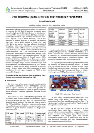
  • 1. INTERNATIONAL RESEARCH JOURNAL OF ENGINEERING AND TECHNOLOGY (IRJET) E-ISSN: A2395-0056 VOLUME: 09 ISSUE: 02 | FEB 2022 WWW.IRJET.NET P-ISSN: 2395-0072 © 2022, IRJET | Impact Factor value: 7.529 | ISO 9001:2008 Certified Journal | Page 365 Decoding DMA Transactions and Implementing VFIO in USB4 Rajat Khandelwal Intel Technology India Pvt. Ltd., Bengaluru, India ----------------------------------------------------------------------***--------------------------------------------------------------------- Abstract—USB4 as a connectivity standard was developed to converge the USB Type-C connector ecosystem along with ultra-high speeds. The typical speed of data transfer over one USB4 transmission line is 20 Gbps making it a total bandwidth of 40 Gbps over two transmission lines. USB4 replaces USB3.2 while retaining USB2.0 bus operating in parallel. A variety of protocols are tunneled over USB4 routers, which include DP/HDMI, USB3 and PCIe. There are various interface adapters distributed throughout a USB4 router, which house address spaces. It’s evident that all the address space cannot be addressed using memory BARs which calls for another method of data transmission – DMA. The various types of interface adapters are addressed in this paper along with the types of address spaces which the routers encompass. The only memory which is mapped directly through memory BARs is the host interface address space. This address space consists of four important sections – Host interface control, transmit descriptor rings, receive descriptor rings, and interrupt control. The memory addressed by BARs resides typically in BAR0, which is why it is possible to map this memory to user space using VFIO mechanism. A short introduction to user space mapping via VFIO is also provided in the paper. Keywords—USB4 specification, Control channels, DMA, Configuration spaces, USB4 adapters, VFIO I. INTRODUCTION We have come a long way from data speeds ranging from 12 Mbps (USB1.1) to 20 Gbps (USB3.2). This dramatic shift of speed advances has only been possible by increasing throughput and the arrival of Type C subsystem which provided a common high-speed interface for the protocols. Thunderbolt and USB4 are two technologies which uses dual speed lanes for data transfer and their speed caps at 40 Gbps (20 Gbps per lane). Both the technologies use standard Type C interface. The important thing to note is that TBT and USB4 are themselves not protocols, but ways to tunnel various protocols. Below is a representation of the difference in speeds of various interfaces and the protocols tunneled by them. USB spec Max speed PHY Type Connectors supported USB1.1 12 Mbps Full Speed Type A USB2.0 480 Mbps High speed Type A USB3.1 Gen1 (1x1) 5 Gbps Super Speed Type A/C USB3.1 Gen2 (2x1) 10 Gbps Super Speed Plus Type A/C USB3.2 (2x2) 20 Gbps Super Speed Plus Type C TBT3 x1 20.625 Gbps CIO Type C TBT3 x2 41.25 Gbps CIO Type C USB4 x1 20 Gbps CIO Type C USB4 x2 40 Gbps CIO Type C An interesting thing to note is that TBT3 tunnels PCIe and DP/HDMI protocols but not USB3. But USB4 tunnels all these 3 protocols. USB2 protocol still exists in modern Type C connectors as a legacy mechanism of data transfer and is not tunneled. Separate D+/D- channels run through Type C connector to support USB2 single lane protocol. The supporting mechanism through which USB4 work is by tunneling the protocols through routers. The router which is present in the host is termed as host router. Similarly, we have device routers which can be connected in the form of daisy chain subsequently. Below is a figure which represents USB4 gatkex card supplied by Intel. Fig. 1. USB4 gatkex card (Intel generic) The USB4 gatkex card shown above is basically a USB4 device router from within. The above figure has 3 downstream Type C ports and 1 upstream Type C port. The upstream port can be connected to a host Type C receptacle through a thunderbolt cable. We will see how a router is laid out in a USB4 specification. Each router has 3 adapters – Protocol adapters, Control adapters, and Lane adapters. Each router has its own router configuration space. The protocol and lane adapters have adapter, path and counters configuration spaces. Point to note is that there are two lane adapters in each router since there are two lanes each providing a throughput of 20 Gbps.
  • 2. INTERNATIONAL RESEARCH JOURNAL OF ENGINEERING AND TECHNOLOGY (IRJET) E-ISSN: A2395-0056 VOLUME: 09 ISSUE: 02 | FEB 2022 WWW.IRJET.NET P-ISSN: 2395-0072 © 2022, IRJET | Impact Factor value: 7.529 | ISO 9001:2008 Certified Journal | Page 366 The protocol adapters are subdivided into upstream and downstream protocol adapters which are specific to USB3, PCIe and DP/HDMI. They are basically used to convert USB4 traffic into protocol traffic and vice versa. There exists a host interface adapter which is present in the host interface layer. This layer houses N transmit descriptor rings and N receive descriptor rings. The transmit ring and receive ring with hop ID 0 is used to communicate between host (connection manager) and the USB4 domain. This host interface layer houses certain registers which are mapped via memory PCIe BARs. The configuration spaces however are large and thus can only be addressed through DMA. This paper primarily focuses on how the DMA transactions take place and what they are made of. Further we will see how can we map the host interface layer to user space via VFIO. II. LAYOUT OF A ROUTER A USB4 router can be theoretically represented in the form given below. Fig. 2. Representation of a USB4 router This router contains two downstream USB4 Type C ports and one upstream port. As we can see, there are PCIe upstream and PCIe downstream adapters corresponding to the direction of the data flow. Similarly, we have USB3 upstream and downstream adapters. There is also a time management unit (TMU) which supports time synchronization within routers. As represented in the figure, USB2 lanes run separately through a channel which is called D+/D- channel in Type C receptacle. III.ADAPTERS AND CONFIG SPACES There are three types of adapters in a USB4 router – Protocol adapters, Control adapters and Lane adapters. We have two types of protocol adapters – Host interface adapter and generic protocol adapters (USB3/DP/HDMI/PCIe). All the adapters except control adapters house configuration spaces – Adapter config space, Path config space and Counter config space. In addition, each router also has its own router config space and a sideband (SB) register space which is addressed through SBU transactions. As explained earlier, the registers residing in host interface layer can be easily addressed using memory BAR0. And thus, they can be easily ported to user space using VFIO. The configuration spaces can only be addressed using DMA. The figure given below represents various layers and adapters in a USB4 router. Fig. 3. USB4 adapters across functional layers IV.TRANSPORT LAYER All the packets on arriving a router are directed toward transport layer. Following is the direction flow of all the packets that are present as a part of USB4 transaction. A. Control packets: A read/write control packet can be transmitted from host to a router and from a router to a host. When the flow direction is from host to router, the packet is transmitted from host to host interface adapter, then it goes to control adapter, then to the transport layer and then to the respective configuration space. Similarly a control packet received from a router’s configuration space is transmitted from configuration space to transport layer to control adapter to host interface layer to lane adapter to finally host. B. USB3 packets: For the USB3 packets going from USB3 host to router, the transmission flow is USB3 host to USB3 interface adapter to control adapter to transport layer to respective adapter. C. PCIe packets: PCIe packets are transmitted from a PCIe end point to a PCIe bridge (if exists) to PCIe interface adapter to control adapter to transport layer to respective adapter. D. DP/HDMI packets: DP/HDMI packets are direct flow packets. They have a source and destination. They originate from a DP/HDMI source and are transmitted to DP/HDMI interface adapter to control adapter to transport layer to respective adapter.
  • 3. INTERNATIONAL RESEARCH JOURNAL OF ENGINEERING AND TECHNOLOGY (IRJET) E-ISSN: A2395-0056 VOLUME: 09 ISSUE: 02 | FEB 2022 WWW.IRJET.NET P-ISSN: 2395-0072 © 2022, IRJET | Impact Factor value: 7.529 | ISO 9001:2008 Certified Journal | Page 367 E. Link type transactions: These originate from logical layer and are used during lane initialization. They are also used to signal a change in adapter state due to events such as a lane disconnect or transition to a low power state. LT transactions are transmitted from logical layer to control adapter to transport layer to SB (sideband) channel to SB channel of another router to control adapter to transport layer to respective SB register space. F. Administrative type transactions: AT transactions are used at the time of router enumeration and they serve the purpose of identifying lanes, generation and speed in a router. They have the same route as that of link type transactions. These are also SB transactions and are transmitted along the SBU lines. G. Broadcast retimer type transactions: BRT transactions are also SB transactions which are transmitted to enumerate retimers. There can be a maximum of 6 retimers between two routers. Thus retimer numbering can go from 1 to maximum of 6. BRT transactions occur in both directions from router A to router B and vice versa. They have the same path as that of LT transactions. H. Addressed retimer transactions: ART transactions are solely used for TxFFE negotiations. There exists a TxFFE register in SB register space of each router. ART transactions follow the same route as that of LT transactions. V. TIME SYNCHRONIZATION The Time Synchronization Protocol is a distributed protocol that defines how the real-time clocks in a USB4 fabric synchronize with each other. The real-time clocks are organized into a hierarchy with the host router at the top of the hierarchy determining the reference time for the entire domain. Clock synchronization is achieved by exchanging ordered sets and time sync packets where downstream devices use both local timestamps and the timing information in the time sync Packets to adjust their clocks to the time of the host router. When Inter-Domain time synchronization is disabled, the time synchronization protocol executes within the scope of a single domain. All time sync packets, state machines and other entities are associated with a single domain. The time established within one domain by the protocol is independent of the time in other domains. When Inter-Domain time synchronization is enabled, the time synchronization protocol executes within the scope of an interconnected set of domains. The Connection Manager s of the domain establish an Inter-Domain clock synchronization hierarchy by selecting one of the host routers to be the time source for all domains. The time synchronization protocol then synchronizes the clocks of the other domains to the Inter-Domain host router clock. [3] VI.LANE ADAPTER STATE MACHINE The state machine in the given figure describes the behavior of the logical layer in a lane adapter. A detailed description of the states and transitions between states follows. A. Disabled state: The lane adapter disables the lane. B. CLd state: Lane adapter transmitter and receiver are inactive. C. Training state: The lane adapter performs symbol synchronization and transfer of lane parameters. D. CL0 state: The lane adapter can transmit and receive transport layer packets across the lane. E. Lane bonding state: bonds two single lane links into a dual lane link. F. CL0s, CL1 and CL2 state: Low power states. [3] VII. ROUTER CONFIGURATION SPACE The following configuration registers are present in router config space. Register name Bit(s) Field name ROUTER_CS_0 15:0 Vendor ID 31:16 Device ID ROUTER_CS_1 7:0 Next capability pointer 13:8 Upstream adapter 19:14 Max adapter 22:20 Depth ROUTER_CS_2 23 Rsvd
  • 4. INTERNATIONAL RESEARCH JOURNAL OF ENGINEERING AND TECHNOLOGY (IRJET) E-ISSN: A2395-0056 VOLUME: 09 ISSUE: 02 | FEB 2022 WWW.IRJET.NET P-ISSN: 2395-0072 © 2022, IRJET | Impact Factor value: 7.529 | ISO 9001:2008 Certified Journal | Page 368 31:24 Revision number ROUTER_CS_3 31:0 Topology ID low ROUTER_CS_4 23:0 Topology ID high 30:24 Rsvd 31 Topology ID valid ROUTER_CS_5 7:0 Notification timeout 15:8 CM USB4 version 23:16 Rsvd 31:24 USB4 version ROUTER_CS_6 0 Enter sleep 1 Enable wake on PCIe 2 WO USB3 3 Enable wake on DP 22:4 Rsvd 23 CM TBT3 support 24 PCIe tunneling ON 25 USB3 tunneling ON 26 Internal host controller ON 30:27 Rsvd 31 Configuration valid ROUTER_CS_7 0 Sleep ready 1 TBT3 not supported 2 Wake on PCIe status 3 Wake on USB3 status 4 Wake on DP status 17:5 Rsvd 18 Internal host controller implemented 23:19 Rsvd 24 Router ready 25 Config ready 31:26 Rsvd ROUTER_CS_8 31:0 UUID high ROUTER_CS_9 31:0 UUID low ROUTER_CS_10 31:0 Data[0] ROUTER_CS_11 31:0 Data[1] ROUTER_CS_12 31:0 Data[2] ROUTER_CS_13 31:0 Data[3] ROUTER_CS_14 31:0 Data[4] ROUTER_CS_15 31:0 Data[5] ROUTER_CS_16 31:0 Data[6] ROUTER_CS_17 31:0 Data[7] ROUTER_CS_18 31:0 Data[8] ROUTER_CS_19 31:0 Data[9] ROUTER_CS_20 31:0 Data[10] ROUTER_CS_21 31:0 Data[11] ROUTER_CS_22 31:0 Data[12] ROUTER_CS_23 31:0 Data[13] ROUTER_CS_24 31:0 Data[14] ROUTER_CS_25 31:0 Data[15] ROUTER_CS_26 31:0 Metadata ROUTER_CS_27 15:0 Opcode 23:16 Rsvd 29:24 Status 30 Operation not supported 31 Operation valid The above table is provided to give a representation of what a router config space looks like. VIII.ADAPTER CONFIGURATION SPACE Every adapter (except for a control adapter) shall have its own adapter configuration space. The adapter configuration space structure begins with a set of doublewords describing the basic attributes of an adapter. The rest of the space is populated with a linked list of capabilities. A Connection Manager reads from or writes to adapter configuration space using the read requests and write requests defined. A router shall allow a Connection Manager to access adapter configuration space regardless of whether or not the adapter is connected.[3] IX.USB4 HOST MEMORY The host interface layer of a USB4 router houses these registers: Offset Register name Host interface control 39640h Host interface capabilities 39858h Host interface reset 39864h Host interface control 39880h Host interface CL1 enable 39884h Host interface CL2 enable Transmit descriptor rings 00000h + n*10h Base address low 00004h + n*10h Base address high 00008h + n*10h Producer and consumer
  • 5. INTERNATIONAL RESEARCH JOURNAL OF ENGINEERING AND TECHNOLOGY (IRJET) E-ISSN: A2395-0056 VOLUME: 09 ISSUE: 02 | FEB 2022 WWW.IRJET.NET P-ISSN: 2395-0072 © 2022, IRJET | Impact Factor value: 7.529 | ISO 9001:2008 Certified Journal | Page 369 indexes 0000Ch + n*10h Ring size 19800h + n*20h Ring control Receive descriptor rings 08000h + n*10h Base address low 08004h + n*10h Base address high 08008h + n*10h Producer and consumer indexes 0800Ch + n*10h Ring and buffer size 29800h + n*20h Ring control 29804h + n*20h PDF bit masks Interrupts 37800h : 37800h + (4 * ceiling(3N/32) – 1) Interrupt status (ISR) 37808h : 37808h + (4 * ceiling(3N/32) – 1) Interrupt status clear (ISC) 37810h : 37810h + (4 * ceiling(3N/32) – 1) Interrupt status set (ISS) 38200h : 38200h + (4 * ceiling(3N/32) – 1) Interrupt mask (IMR) 38208h : 38208h + (4 * ceiling(3N/32) – 1) Interrupt mask clear (IMC) 38210h : 38210h + (4 * ceiling(3N/32) – 1) I Interrupt mask set (IMS) 38C00h : 38C3Ch Interrupt throttling rate (ITR) 38C40h : 38C40h + (4 * ceiling(3N/8) – 1) Interrupt vector allocation (IVAR) 18C00h :18C00h + (4 * ceiling(N/8) – 1) Receive ring vacancy control 19400h :19400h + (4 * ceiling(N/32) – 1) Receive ring vacancy status Here n represents the hop ID of the ring. X. CONTROL RINGS AND DMA MAPPING A finite number of transmit descriptor and receive descriptor rings are allocated by the connection manager. In Linux, the number is 10, i.e., the number of hop IDs allocated is 10. The ring with hop ID 0 is called control ring since it is used extensively by the connection manager to read/write configuration spaces (control packets). A DMA address is allocated via coherent kernel methods for each transmit/receive ring. The respective DMA address of a ring is then written into ‘base address low’ and ‘base address high’ fields in the host memory (Refer sec. IV) corresponding to the respective ring. ‘Ring size’ field also gets written (in Linux, with a value of 10), i.e., a total of 10 descriptors per ring. The producer and consumer index fields get written to 0 for each ring initially. XI.TRANSMIT INTERFACE The table below depicts the contents of a transmit descriptor. DW Bits Name 0 0-31 Address low 1 0-31 Address high 2 0-11 Data length 12-15 EOF PDF 16-19 SOF PDF 20 Rsvd 21 Descriptor done 22 Request done 23 Interrupt enable 3 0-31 Rsvd  Address low – lower 32 bits of DMA address of the buffer to be transmitted  Address high – higher 32 bits of DMA address of the buffer to be transmitted  Data length – No of bytes to be transmitted from this data buffer  EOF PDF – PDF value of the transport layer packet containing this buffer; PDF – protocol defined field  SOF PDF – Ignore  Descriptor done – Set to 0 when posting a data buffer to be transmitted. If ‘Request Status’ field is set to 1, host interface layer sets this field to 1 after the last byte is sent to transport layer. If ‘Request Status’ field is set to 0, host interface layer doesn’t write to this field  Request Status – Determines the update policy of ‘Descriptor done’ field  Interrupt enable – If set to 1, host interface layer issues an interrupt to the connection manager after updating ‘Descriptor done’ field Producer index of transmit ring – Index of the next transmit descriptor the host writes to. Consumer index of transmit ring – Index of the next transmit descriptor to be processed by host interface layer. The buffer to be transmitted is appended with a CRC to detect inconsistency in data transmitted. The buffer is allocated a DMA address via coherent kernel methods and the address is stored in ‘Address low’ and ‘Address high’ fields in the transmit descriptor present at producer index of the transmit ring with hop ID 0. The transmission of descriptor to host interface layer starts when producer index ≠ consumer index. Initially, both are set to 0 by the connection manager. So, when transmission is to start, producer index is increased by 1. Now, the transmit descriptor at producer index is
  • 6. INTERNATIONAL RESEARCH JOURNAL OF ENGINEERING AND TECHNOLOGY (IRJET) E-ISSN: A2395-0056 VOLUME: 09 ISSUE: 02 | FEB 2022 WWW.IRJET.NET P-ISSN: 2395-0072 © 2022, IRJET | Impact Factor value: 7.529 | ISO 9001:2008 Certified Journal | Page 370 transmitted to the host interface layer. The DMA address of this transmit descriptor is calculated by increasing the address contained in ‘base address low’ and ‘base address high’ fields of host interface memory transmit ring by the producer index. The host interface layer processes the transmit descriptor and fetches the buffer at DMA address present in ‘address low’ and ‘address high’ fields of the descriptor. The host interface layer is also responsible to prepend the transport layer packet header into the buffer fetched from host memory. Now this transport layer packet is appended a PDF packet equal to EOF PDF field of the transmit descriptor. When the last byte of the transport packet formed is transmitted to transport layer, the host interface layer increases the consumer index by 1 and updates the ‘Descriptor done’ field depending on ‘Request done’ field and issues an interrupt according to the ‘Interrupt enable’ field set by the connection manager. The host on receiving an interrupt comes to know that the buffer is successfully transmitted to the transport layer. XII. RECEIVE INTERFACE The table below depicts the contents of a receive descriptor. DW Bits Name 0 0-31 Address low 1 0-31 Address high 2 0-11 Data length 12-15 EOF PDF 16-19 SOF PDF 20 CRC error 21 Descriptor done 22 Buffer overflow 23 Interrupt enable 24-31 Offset 3 0-31 Rsvd  Address low – lower 32 bits of DMA address of the data buffer to receive contents from the domain  Address high – higher 32 bits of DMA address of the data buffer to receive contents from the domain  Data length – No of bytes to be received in the data buffer  EOF PDF – PDF value of the transport layer packet carrying data from a transmit descriptor  SOF PDF – Set to 0  CRC error – indicates if there is an error in the frame CRC  Descriptor done – Set to 0 initially. If ‘Request Status’ field is set to 1, host interface layer sets this field to 1 after the last byte is sent to host memory. If ‘Request Status’ field is set to 0, host interface layer doesn’t write to this field  Request Status – Determines the update policy of ‘Descriptor done’ field  Interrupt enable – If set to 1, host interface layer issues an interrupt to the connection manager after updating ‘Descriptor done’ field  Offset – offset of the host memory data buffer at which the data is to be received Producer index of receive ring - Index of the next receive descriptor that the host interface layer writes to. Consumer index of receive ring - Index of the next receive descriptor that the host provides to the host interface layer. The data buffer in the host memory is allocated a DMA address via coherent kernel methods and the address is stored in ‘Address low’ and ‘Address high’ fields in the receive descriptor present at consumer index of the receive ring with hop ID 0. The transmission of buffer from transport layer to host memory starts when producer index ≠ consumer index. Initially, both are set to 0 by the connection manager. So, when transmission is to start, consumer index is increased by 1. Now, the receive descriptor at consumer index is filled by the host interface layer. The DMA address of this receive descriptor is calculated by increasing the address contained in ‘base address low’ and ‘base address high’ fields of host interface memory receive ring by the consumer index. The host interface layer increases producer index by 1 and fetches the transport layer packet from the transport layer and posts the content at the DMA address present in ‘address low’ and ‘address high’ fields of the descriptor. The host interface layer is also responsible to remove the transport layer header from the packet received from the transport layer. The host interface layer sets the ‘Buffer overflow’ bit if the size of the payload exceeds the available size in the data buffer in the host memory. When the last byte of the transport packet formed is transmitted to host memory, the host interface layer updates the ‘Descriptor done’ field depending on ‘Request done’ field and issues an interrupt according to the ‘Interrupt enable’ field set by the connection manager.
  • 7. INTERNATIONAL RESEARCH JOURNAL OF ENGINEERING AND TECHNOLOGY (IRJET) E-ISSN: A2395-0056 VOLUME: 09 ISSUE: 02 | FEB 2022 WWW.IRJET.NET P-ISSN: 2395-0072 © 2022, IRJET | Impact Factor value: 7.529 | ISO 9001:2008 Certified Journal | Page 371 The host on receiving an interrupt comes to know that the buffer is successfully received in the host memory. Thus, it can be proved that the transmit/receive flow requires two separate DMA transactions, which is illustrated in the figure below. Fig. 4. Pictorial representation of DMA flows in transmit and receive descriptors A crucial point to note is that for DMA transactions to happen on any PCIe endpoint device, bus mastering needs to be enabled. Thus, a value of PCI_COMMAND_MASTER (0x4) is stored in the PCI_COMMAND register in PCIe config space by the connection manager. XIII.VFIO The VFIO driver framework provides unified APIs for direct device access. It is an IOMMU/device-agnostic framework for exposing direct device access to user space in a secure, IOMMU-protected environment. This framework is used for multiple devices, such as GPUs, network adapters, and compute accelerators. With direct device access, virtual machines or user space applications have direct access to the physical device.[4] Devices are the main target of any I/O driver. Devices typically create a programming interface made up of I/O access, interrupts, and DMA. Without going into the details of each of these, DMA is by far the most critical aspect for maintaining a secure environment as allowing a device read-write access to system memory imposes the greatest risk to the overall system integrity. VFIO makes use of containers which hold one/more groups. A container is created by simply opening the character device exposes by VFIO in sysfs - /dev/vfio/vfio. On its own, the container provides very little functionality. The user has to add groups in the container for the next level of abstraction. This is done easily by unbinding the native driver to the device and binding it to vfio-pci driver. By doing so, a VFIO group will appear in sysfs as /dev/vfio/<GROUP>. Here, GROUP is the IOMMU group number of which the device is a member. If more than one device is a member of the group, all the devices should be added in the group by unbinding and binding. Once the group is prepared, it is attached to the container using VFIO_GROUP_SET_CONTAINER ioctl call, passing the file descriptor the container file opened. All the ioctl calls which are associated with VFIO are present in the linux/vfio.h file. Here, we give a prepared code to map the host interface memory of host USB4 router and read the number of paths. The number of paths is present in bits [10:0] of Host interface capabilities register in host interface layer. The steps to do so by VFIO are listed below: A. Enable the vfio-pci driver by setting the kernel config: CONFIG_VFIO_PCI=y. B. Unbind the native thunderbolt driver from the USB4 PCIe device. C. Bind the vfio-pci driver to the device. D. Check if there are other devices present in the iommu group the USB4 device is in. If so, unbind their respective drivers and bind the vfio-pci driver. E. Create a container by opening the character file /dev/vfio/vfio. F. Open the group created in sysfs under /dev/vfio/<GROUP>. G. Bind the group to the container created by using VFIO_GROUP_SET_CONTAINER ioctl call. H. Enable type 1 IOMMU by using VFIO_SET_IOMMU ioctl call. I. Get the BAR0 region information using VFIO_DEVICE_GET_REGION_INFO ioctl call. J. The above region information contains size and offset. So, now map the region using mmap system call with the given size and offset.
  • 8. INTERNATIONAL RESEARCH JOURNAL OF ENGINEERING AND TECHNOLOGY (IRJET) E-ISSN: A2395-0056 VOLUME: 09 ISSUE: 02 | FEB 2022 WWW.IRJET.NET P-ISSN: 2395-0072 © 2022, IRJET | Impact Factor value: 7.529 | ISO 9001:2008 Certified Journal | Page 372 K. That’s it. Now the BAR0 has been completely mapped and now you can access any register by dereferencing pointer address. The complete code to map the host interface layer registers and print the number of paths is given in the below link: https://github.com/rajatkha/libusb4 ACKNOWLEDGMENT I would like to acknowledge Intel for providing me this opportunity to share my research work on USB4. I would also like to thank Rajaram Regupathy who helped me in mapping host interface memory through VFIO. REFERENCES [1] Tailor Neel Kishorkumar, “USB3.0 protocol” [2] POINTGREY Innovation in Imaging, “USB 3.0: Improvements over USB 2.0”, February, 2013 [3] Apple Inc, HP Inc, Intel Corporation, Microsoft Corporation, Renesas Corporation, STMicroelectronics, Texas Instruments, “Universal Serial Bus 4 (USB4) Specification”, revision 1.0, October, 2020 [4] Neo Jia, Kirti Wankhede, “VFIO Mediated Devices”, 2016 [5] Alex Williamson, “VFIO: A User’s Perspective”, November, 2012 [6] Intel Corporation, “Intel USB4 Evaluation Dock EVB User Manual”, revision 4.0, May, 2021 [7] Sony, “What are the USB4 data transfer rates and specifications?”, March, 2022