Wireless adhoc multi access networks
•
1 like•286 views

One of the most attractive field for research for researchers and authors so the Wireless adhoc networks. So, this paper will describe the background and basic features of Open Short Path First (OSPF) routing protocol due to multi-access networks. Explaining and practice on the OSPF configuration commands. Describe, modify and calculate the metric (Cost) used by OSPF due to adhoc networks. Illustrating the Election parameters made by DR/BDR (Designated and Back Designated) Routers used in multi-access wireless networks. This paper will use OSPF routing protocol because of its average administrative distance with all routing protocols.
![International Journal of Computer Networks & Communications (IJCNC) Vol.7, No.2, March 2015
60
Fig2. OSPF Development timeline
2. ILLUSTRATING THE PROBLEM:
This paper aim is actually to make all end devices under coverage area and under control. adhoc
network of multi-access end devices major issue is the time delay and Packets which dropped
during the transmission process. OSPF Routing Protocol can be handled in this paper because of
its high signal transmission ratio, average administrative routing protocol distance, high
authentication and encryption algorithm that already defined. OSPF primary feature is the using
of the links speed only however all other protocols used the hops as primary feature. This will
gain much more accurate results in the Adhoc wireless networking case.
3.OSPF working phenomena:
OSPF invented to correct the wrong paths made by RIP Routing Protocol. Whichinvented by the
routing table entry algorithm called BelmmanFord (Hops Theory).[1]Note that Network Layer
(Layer3) on the Open System Interconnection (OSI) model will be ussed. The packet
encapsulation in the sending criteria must be defined as OSPF Message Encapsulation packet
header contains router ID, area ID and Type code for OSPF packet type.
Fig3. Encapsulation OSPF Message
Internet Protocol (IP) packet header contains source IP address, destination IP address and
protocol field set to 89.[2] The data link frame header contains source Multi Access Card (MAC)
address and Destination MAC address. There are 5 types of packet messages for the OSPF listed
as bellow.](data:image/gif;base64,R0lGODlhAQABAIAAAAAAAP///yH5BAEAAAAALAAAAAABAAEAAAIBRAA7)
Recommended
More Related Content
What's hot
What's hot (19)
Viewers also liked
Viewers also liked (19)
Similar to Wireless adhoc multi access networks
Similar to Wireless adhoc multi access networks (20)
More from IJCNCJournal
More from IJCNCJournal (20)
Recently uploaded
Recently uploaded (20)
Wireless adhoc multi access networks
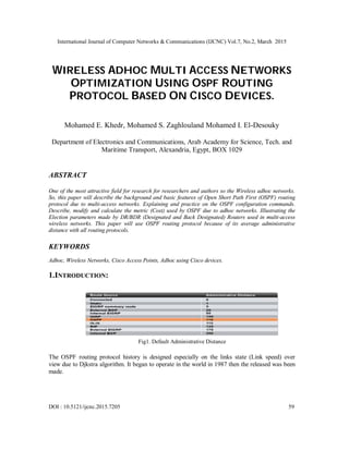
- 1. International Journal of Computer Networks & Communications (IJCNC) Vol.7, No.2, March 2015 DOI : 10.5121/ijcnc.2015.7205 59 WIRELESS ADHOC MULTI ACCESS NETWORKS OPTIMIZATION USING OSPF ROUTING PROTOCOL BASED ON CISCO DEVICES. Mohamed E. Khedr, Mohamed S. Zaghlouland Mohamed I. El-Desouky Department of Electronics and Communications, Arab Academy for Science, Tech. and Maritime Transport, Alexandria, Egypt, BOX 1029 ABSTRACT One of the most attractive field for research for researchers and authors so the Wireless adhoc networks. So, this paper will describe the background and basic features of Open Short Path First (OSPF) routing protocol due to multi-access networks. Explaining and practice on the OSPF configuration commands. Describe, modify and calculate the metric (Cost) used by OSPF due to adhoc networks. Illustrating the Election parameters made by DR/BDR (Designated and Back Designated) Routers used in multi-access wireless networks. This paper will use OSPF routing protocol because of its average administrative distance with all routing protocols. KEYWORDS Adhoc, Wireless Networks, Cisco Access Points, Adhoc using Cisco devices. 1.INTRODUCTION: Fig1. Default Administrative Distance The OSPF routing protocol history is designed especially on the links state (Link speed) over view due to Djkstra algorithm. It began to operate in the world in 1987 then the released was been made.
- 2. International Journal of Computer Networks & Communications (IJCNC) Vol.7, No.2, March 2015 60 Fig2. OSPF Development timeline 2. ILLUSTRATING THE PROBLEM: This paper aim is actually to make all end devices under coverage area and under control. adhoc network of multi-access end devices major issue is the time delay and Packets which dropped during the transmission process. OSPF Routing Protocol can be handled in this paper because of its high signal transmission ratio, average administrative routing protocol distance, high authentication and encryption algorithm that already defined. OSPF primary feature is the using of the links speed only however all other protocols used the hops as primary feature. This will gain much more accurate results in the Adhoc wireless networking case. 3.OSPF working phenomena: OSPF invented to correct the wrong paths made by RIP Routing Protocol. Whichinvented by the routing table entry algorithm called BelmmanFord (Hops Theory).[1]Note that Network Layer (Layer3) on the Open System Interconnection (OSI) model will be ussed. The packet encapsulation in the sending criteria must be defined as OSPF Message Encapsulation packet header contains router ID, area ID and Type code for OSPF packet type. Fig3. Encapsulation OSPF Message Internet Protocol (IP) packet header contains source IP address, destination IP address and protocol field set to 89.[2] The data link frame header contains source Multi Access Card (MAC) address and Destination MAC address. There are 5 types of packet messages for the OSPF listed as bellow.
- 3. International Journal of Computer Networks & Communications (IJCNC) Vol.7, No.2, March 2015 61 Fig.4 OSPF Packets Type OSPF not only good due to administrative distance but also it is very good in the authentication andencryption purposes for important data. Routers will only accept routing information from other routers that have been configured with the same password or authentication information Fig.5 Showing Authentication 4. USED NETWORK’S DEVICES: It is urgent to use network devices in this research, that’s why routing must be made using high speed, reliable routers. This options are only exists in cisco devices. So a 3X 2600 series cisco routers (2621XM) routers with 2 -38db antennas will be used to make sure the coverage are is good enough and can cover about 1Km.[3] Fig.6. Cisco 2800 Series Catalyst Router
- 4. International Journal of Computer Networks & Communications (IJCNC) Vol.7, No.2, March 2015 62 5. DESIGNED SCHEMA TO WORK ON: This schema is designed using Cisco packet tracer simulator. We will use 3 2611xm routers as mentioned. The 3 routers connected directly by smart serial interfaces not wirelessly (to check the connection first).[4] The DCE interfaces used only to establish the connection with the universal rate of 64000 bit/sec. every router have its own network of end devices. Ip configuration as listed below and as shown and configured in Appendix A, B and C: Table1: Schema Design Device/interface IP Address+ Subnet mask Device/interface IP Address+ Subnet mask Adhoc 1 172.16.1.18 255.255.255.192 R3/Lo0 10.3.3.3 255.255.255.255 Adhoc 2 10.10.10.2 255.255.255.0 R3/S0/0/0 192.168.10.5 255.255.255.252 Adhoc 3 172.16.1.35 255.255.255.248 R3/S0/0/1 192.168.10.10 255.255.255.252 R1/Lo0 10.1.1.1 255.255.255.255 R1 – R2 Cost 64 Kbps R1/S0/0/0 192.168.10.1 255.255.255.252 R2-R3 Cost 128 Kbps R1/S0/0/1 192.168.10.6 255.255.255.252 R1-R3 Cost 256 Kbps R2/Lo0 10.2.2.2 255.255.255.255 R1 LAN 172.16.1.16 255.255.255.192 R2/S0/0/0 192.168.10.2 255.255.255.252 R2 LAN 10.10.10.0 255.255.255.0 R2/S0/0/1 192.168.10.9 255.255.255.252 R3 LAN 172.16.1.32 255.255.255.248 Fig7. OSPF Path cost (a)
- 5. International Journal of Computer Networks & Communications (IJCNC) Vol.7, No.2, March 2015 63 6. OSPFPATH COST METRIC Usually there is a difference in actual bandwidth and the used bandwidth [5].So, the actual speed can be determined using the bandwidth. The main Reason is the routing table has best path information. The show interface command will display interface’s bandwidth. Serial links used as shown in as bellow figure. Fig8. OSPF Path Cost (b) 7. CONFIGURATION OF OSPF ROUTER Configuration the path cost of a must be configured in link both sides of a serial link should be configured with the samebandwidth. Commands used to modify bandwidth valueBandwidth command Router(config-if)#bandwidth 64 Fig9. OSPF bandwidth configuration
- 6. International Journal of Computer Networks & Communications (IJCNC) Vol.7, No.2, March 2015 64 Fig10. OSPF bandwidth configuration Editing the Cost of the link linking between bandwidth command and the ipospf path cot command. Ipospf cost command. Sets cost to a specific value then the calculated OSPF Cost already calculated.[6] Fig11. Equivalent commands of bandwidth and ip PSPF commands 8. OSPF AND MULTI-ACCESS NETWORKS Differences in Multi-access Networks, Point-to-point.[7]Broadcast Multi-access, Non broadcastMulti-access (NBMA), Point-to-multipoint and virtual links.
- 7. International Journal of Computer Networks & Communications (IJCNC) Vol.7, No.2, March 2015 65 Fig12. OSPF Network types used 2 challenges presented by multi-access networks, multiple adjacencies and Extensive Link State Advertisement (LSA) flooding.[8] Fig13. No. Of Growth of paths an acknowledgement of receipt must be sent back to transmitting router due to flooding of LSA and . [9] Fig14. LSA Flooding Scenario
- 8. International Journal of Computer Networks & Communications (IJCNC) Vol.7, No.2, March 2015 66 Solution to LSA flooding issue is the use of designated router (DR) and Backup designated router (BDR). The DR & BDR selection is Routers are elected to send and receive LSA.[10] Fig15. DR/BDR Listens. Various DR routers send LSAs through multicast ip address of 224.0.0.6 to DR & BDRrouters ,DR forward LSA via multicast address 224.0.0.5 to all other routers.[11] Fig16. DR sends LSAs 9.CONCLUSIONS Using OSPF in Multi-access networks of wireless Adhoc with cisco solutions products like routers, switches and access points; it can be easy to make the entire network under coverage with minimum time delay and legacy. In this paper, Appling on real life network as it is and with all right configurations of OSPF on routers, we were able to decrease the time delay and legacy from 22mSec to only 12mSec. This will define a revolution in the adhoc networking in fields of time based like military services.
- 9. International Journal of Computer Networks & Communications (IJCNC) Vol.7, No.2, March 2015 67 REFERENCES [1] http://www.cisco.com/c/en/us/products/wireless/buyers-guide.html [2] SharamHekmat, Communication Networks, 2011 [3] Robert Faludi, A Practical Guide to networking protocols, Building wireless networks, 2013 [4] Patricegilopacovic, Wireless networking, building AdHoc networks.802.11 a/b/g/n techniques, April 2011. [5] Yi-Bing Lin &ImrichChlamtac, Wireless and Mobile network architectures, 2012 [6] Andrew S. Tanenbaum, Computer Networks, Sixth Edition, 2013 [7] Simon Haykin, Communication Systems, fifth edition, 2014 [8] J. F. Kurose and W. R. Ross, Computer Networking: A Top-Down Approach Featuring the Internet, 2014 [9] Andrew S.Tanenbaum, Computer Network, 2012 [10] J. Walrand& P. Varaiya, High-Performance Communication Networks, 2014 [11] Wendell Odom,Cisco CCNA Exam# 200-120 Certification Guide, Cisco Systems, 2014 Appendix A Controller (Routers) Configuration For Controller 1: Router>enable Router#configure terminal Router(config)#hostname Base 1 Controller1(config)#interface fastEthernet 0/0 Controller1(config-if)#ip address 172.16.1.18 255.255.255.192 Controller1(config-if)#no shutdown Controller1(config-if)# %LINK-5-CHANGED: Interface FastEthernet0/0, changed state to up Controller1(config-if)#ip address 11.0.0.1 255.0.0.0 Controller1(config-if)#no shutdown Controller1(config-if)# %LINK-5-CHANGED: Interface FastEthernet0/1, changed state to up Controller1(config)#interface serial 0/3/0 Controller1(config-if)#ip address 12.0.0.1 255.0.0.0 Controller1(config-if)#clock rate 64000 Controller1(config-if)#no shutdown Controller1(config-if)# %LINK-5-CHANGED: Interface Serial0/3/0, changed state to up Controller1(config)#line console 0 Controller1(config-line)#password adhoc1admin Controller1(config-line)#login Controller1(config)#line vty 0 4 Controller1(config-line)#password adhoc1admin Controller1(config-line)#login
- 10. International Journal of Computer Networks & Communications (IJCNC) Vol.7, No.2, March 2015 68 Controller1(config)#ip route 13.0.0.0 255.0.0.0 12.0.0.2 Appendix B For Controller 2: Router>enable Router#configure terminal Router(config)#hostname Base2 Controller2(config)#interface fastEthernet 0/0 Controller2(config-if)#ip address 13.0.0.1 255.0.0.0 Controller2(config-if)#no shutdown Controller2(config-if)# %LINK-5-CHANGED: Interface FastEthernet0/0, changed state to up Controller2(config)#interface fastEthernet 0/1 Controller2(config-if)#ip address 14.0.0.1 255.0.0.0 Controller2(config-if)#no shutdown Controller2(config-if)# %LINK-5-CHANGED: Interface FastEthernet0/1, changed state to up Controller2(config)#interface serial 0/1/0 Controller2(config-if)#ip address 12.0.0.2 255.0.0.0 Controller2(config-if)#no shutdown Controller2(config-if)# %LINK-5-CHANGED: Interface Serial0/3/0, changed state to up Controller2(config)#line console 0 Controller2(config-line)#password adhoc1admin Controller2(config-line)#login Controller2(config)#line vty 0 4 Controller2(config-line)#password adhoc1admin Controller2(config-line)#login Controller2(config)#ip route 10.0.0.0 255.0.0.0 12.0.0.1 Appendix C For Controller 3: Router>enable Router#configure terminal Router(config)#hostname Base3 Controller2(config)#interface fastEthernet 0/0 Controller2(config-if)#ip address 14.0.0.1 255.0.0.0 Controller2(config-if)#no shutdown Controller2(config-if)# %LINK-5-CHANGED: Interface FastEthernet0/0, changed state to up Controller2(config)#interface fastEthernet 0/1
- 11. International Journal of Computer Networks & Communications (IJCNC) Vol.7, No.2, March 2015 69 Controller2(config-if)#ip address 15.0.0.1 255.0.0.0 Controller2(config-if)#no shutdown Controller2(config-if)# %LINK-5-CHANGED: Interface FastEthernet0/1, changed state to up Controller2(config)#interface serial 0/1/0 Controller2(config-if)#ip address 12.0.0.3 255.0.0.0 Controller2(config-if)#no shutdown Controller2(config-if)# %LINK-5-CHANGED: Interface Serial0/3/0, changed state to up Controller2(config)#line console 0 Controller2(config-line)#password adhoc1admin Controller2(config-line)#login Controller2(config)#line vty 0 4 Controller2(config-line)#password adhoc1admin Controller2(config-line)#login Controller2(config)#ip route 10.0.0.0 255.0.0.0 12.0.0.1 Authors Mohamed Khedr obtained his B.Sc. degree from the Arab Academy for Science and Technology, Alexandria, Egypt in 1997, the M.S. degree from same university in 2000, and the Ph.D. degree from Ottawa University, Ottawa, Canada in 2004, all in Electrical Engineering.From 1997 to 2000, He was a Graduate Teaching and research assistant at AAST, Alexandria, Egypt.From 2000 to 2004 He was a Graduate Teaching and research assistant at Ottawa University, Ottawa, Canada. From 2005 to 2009, he was an assistant Professor at AAST, Department of Electronic and communications Engineering, Alexandria, Egypt. Since January 2009, He has been an Associate professor at AAST, Department of Electronic and communications Engineering, Alexandria, Egypt.Since Fall 2005, has been an Adjunct Professor at Virginia Tech, USA. Mohamed S. Zaghloul was born in 1954 in Alex, Egypt, graduate as electrical engineer in 1977 has his master from Alexandria University in 1990 has his PhD in Surface Acoustic wave in 2002 he works as doctor at Arab academy for science and Technology in electronic and communication department . Mohamed I. El-Desoukywas born in 1989 in Alex, Egypt, graduate as electrical, Electronics and Communications engineer from The Arab Academy for Science, Technology and Maritime Transport in 2010, has started preparation his master from the same institute of graduation in 2011.