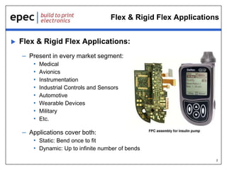
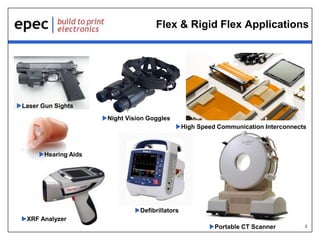
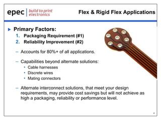
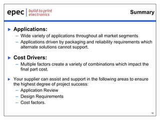
 DELIVERING QUALITY SINCE 1952.
Flex & Rigid Flex PCB’s:
Applications & Cost Drivers
08/28/2015
2
Flex & Rigid Flex Applications
 Flex & Rigid Flex Applications:
– Present in every market segment:
• Medical
• Avionics
• Instrumentation
• Industrial Controls and Sensors
• Automotive
• Wearable Devices
• Military
• Etc.
– Applications cover both:
• Static: Bend once to fit
• Dynamic: Up to infinite number of bends
3
Flex & Rigid Flex Applications
Laser Gun Sights
High Speed Communication Interconnects
Night Vision Goggles
Hearing Aids
Defibrillators
Portable CT Scanner
XRF Analyzer
4
Flex & Rigid Flex Applications
 Primary Factors:
1. Packaging Requirement (#1)
2. Reliability Improvement (#2)
– Accounts for 80%+ of all applications.
– Capabilities beyond alternate solutions:
• Cable harnesses
• Discrete wires
• Mating connectors
– Alternate interconnect solutions, that meet your design
requirements, may provide cost savings but will not achieve as
high a packaging, reliability or performance level.
5
Flex & Rigid Flex Applications:
Packaging
 Size Reduction:
– Occupies down to 10% the “space” of alternate solutions.
– Circuit density capability of Rigid PCBs.
– Tighter bend capabilities than wires / cables.
– Reduced rigid board space requirements
– Reduced enclosure dimension
opportunities
 Weight Reduction:
– Down to 10% of alternate solutions
– Improved Shock & Vibration
performance
6
Flex & Rigid Flex Applications:
Packaging
 Added Functionality:
– Increased number of available interconnects between rigid areas
 Component Reduction:
– Connectors:
• Rigid – Flex constructions eliminate connectors completely
• ZIF Connectors:
– One part connector system.
– Flex circuit direct plug in with mating connector
• Lap Joint Direct Solder
– Flex Soldered directly to PCB
– Components:
• Higher level of design integration
may allow for reduced component
requirements.
7
Flex & Rigid Flex Applications:
Reliability
 Point of Failure Reduction:
– Reduced number of interconnects required:
• Connector solder joints
• Mating connector interfaces
• Wire / Cable crimp connections
 Improved Shock & Vibration Performance
– Reduced weight
– Reduced number of interconnects
8
Flex & Rigid Flex Applications:
Additional Items
 High Speed Signal Integrity:
– Exceptional performance over a wide range of requirements
• Lower material DK values
• Tightly controlled and uniform material thicknesses
• Homogenous flex core construction
 Improved Heat Dissipation:
– Thinner materials and constructions
– Greater surface area to volume ratios
 Assembly Cost Reduction:
– Fewer assembly steps
 Assembly Errors Reduction:
– “One way only” assembly
9
Flex & Rigid Flex Cost Drivers:
Part Size
 Production Panel Manufacturing Process:
– Multiple individual parts arranged within a larger format production
panel (Same as traditional rigid boards)
– Applies to Roll to Roll manufacturing
 Material Quantity Requirements:
– Number of panels required to yield required number of parts.
– Higher quantity of parts per panel reduces total material
requirements and lowers per unit cost
 Design Configuration:
– Excessive levels of integration may lead to large part
configurations
 Part Length:
– May not match “well” with available production panel sizes
10
Flex & Rigid Flex Cost Factors:
Part Shape
 Design Configuration:
– Technology allows for many unique configurations and shapes.
– Part shape / size combination may limit ability to “nest” parts within
a production panel decreasing material utilization:
• Circular or U shapes with empty center sections
• Non-rectangular configurations with unique angles and or extensions
11
Flex & Rigid Flex Cost Factors:
Manufacturing Process
 Manufacturing Process Requirements:
– May dictate specific part orientations thus reducing parts per panel
• Rigid or rigidized areas to
flex areas relationship
• Stiffeners
• PSAs (Double Sided Adhesives)
• Breakaway tabs
– assembly arrays
12
Flex & Rigid Flex Cost Factors:
Layer Count & Construction
 Flex Layer Count:
– Additional more costly materials
– Added Flex layer lamination process(s)
13
Flex & Rigid Flex Cost Factors:
Layer Count & Construction
 Flex Layer Count (continued)
14
Flex & Rigid Flex Cost Factors:
Layer Count & Construction
 Flex Layer Configuration:
– Air Gap Vs Single Stack Construction
• Added Coverlay materials & Coverlay lamination process for each flex
layer pair
15
Flex & Rigid Flex Cost Factors:
Technology Requirements:
 Blind & Buried Vias:
– Added drilling, plating and lamination cycle(s)
– May also require more costly materials
 Via Fill:
– Required for Via in Pad component & fine pitch BGA applications
 Flex Only Area Plated Holes:
– Added drilling & plating cycle(s)
• Sequential build process
 Flex Area Stiffeners:
• Added material(s)
• Added lamination cycle(s)
 Epoxy Strain Reliefs:
– Applied to rigid to flex transitions if required
16
Summary
 Applications:
– Wide variety of applications throughout all market segments
– Applications driven by packaging and reliability requirements which
alternate solutions cannot support.
 Cost Drivers:
– Multiple factors create a variety of combinations which impact the
final part cost.
 Your supplier can assist and support in the following areas to ensure
the highest degree of project success:
– Application Review
– Design Requirements
– Cost factors.
17
Our Products
Battery Packs Flex & Rigid-Flex PCB’s User Interfaces
Fans & Motors Cable Assemblies Printed Circuit Boards
18
Design Centers & Technical Support
 Battery Pack & Power Management – Denver, CO
 User Interfaces – Largo, FL
 Fans & Motors – Wales, UK
 PCB’s – New Bedford, MA & Shenzhen, China
 Flex & Rigid Flex – Toronto, Canada
 Cable Assemblies – New Bedford, MA
 Our Engineering and Design teams are ready to help
our customers create world class and cost effective
product solutions.
19
Q&A
 Questions?
– Enter any questions you may have
in the Control Panel
– If we don’t have time to get to it, we
will reply via email
20
Thank You
Check out our previous webinars at www.epectec.com.
For more information email sales@epectec.com.
Stay Connected with Epec Engineered Technologies
Follow us on our social media sites for continuous technical updates and information:

Flex & Rigid-Flex PCB's - Applications and Cost Drivers

  • 1.
     DELIVERING QUALITYSINCE 1952. Flex & Rigid Flex PCB’s: Applications & Cost Drivers 08/28/2015
  • 2.
    2 Flex & RigidFlex Applications  Flex & Rigid Flex Applications: – Present in every market segment: • Medical • Avionics • Instrumentation • Industrial Controls and Sensors • Automotive • Wearable Devices • Military • Etc. – Applications cover both: • Static: Bend once to fit • Dynamic: Up to infinite number of bends
  • 3.
    3 Flex & RigidFlex Applications Laser Gun Sights High Speed Communication Interconnects Night Vision Goggles Hearing Aids Defibrillators Portable CT Scanner XRF Analyzer
  • 4.
    4 Flex & RigidFlex Applications  Primary Factors: 1. Packaging Requirement (#1) 2. Reliability Improvement (#2) – Accounts for 80%+ of all applications. – Capabilities beyond alternate solutions: • Cable harnesses • Discrete wires • Mating connectors – Alternate interconnect solutions, that meet your design requirements, may provide cost savings but will not achieve as high a packaging, reliability or performance level.
  • 5.
    5 Flex & RigidFlex Applications: Packaging  Size Reduction: – Occupies down to 10% the “space” of alternate solutions. – Circuit density capability of Rigid PCBs. – Tighter bend capabilities than wires / cables. – Reduced rigid board space requirements – Reduced enclosure dimension opportunities  Weight Reduction: – Down to 10% of alternate solutions – Improved Shock & Vibration performance
  • 6.
    6 Flex & RigidFlex Applications: Packaging  Added Functionality: – Increased number of available interconnects between rigid areas  Component Reduction: – Connectors: • Rigid – Flex constructions eliminate connectors completely • ZIF Connectors: – One part connector system. – Flex circuit direct plug in with mating connector • Lap Joint Direct Solder – Flex Soldered directly to PCB – Components: • Higher level of design integration may allow for reduced component requirements.
  • 7.
    7 Flex & RigidFlex Applications: Reliability  Point of Failure Reduction: – Reduced number of interconnects required: • Connector solder joints • Mating connector interfaces • Wire / Cable crimp connections  Improved Shock & Vibration Performance – Reduced weight – Reduced number of interconnects
  • 8.
    8 Flex & RigidFlex Applications: Additional Items  High Speed Signal Integrity: – Exceptional performance over a wide range of requirements • Lower material DK values • Tightly controlled and uniform material thicknesses • Homogenous flex core construction  Improved Heat Dissipation: – Thinner materials and constructions – Greater surface area to volume ratios  Assembly Cost Reduction: – Fewer assembly steps  Assembly Errors Reduction: – “One way only” assembly
  • 9.
    9 Flex & RigidFlex Cost Drivers: Part Size  Production Panel Manufacturing Process: – Multiple individual parts arranged within a larger format production panel (Same as traditional rigid boards) – Applies to Roll to Roll manufacturing  Material Quantity Requirements: – Number of panels required to yield required number of parts. – Higher quantity of parts per panel reduces total material requirements and lowers per unit cost  Design Configuration: – Excessive levels of integration may lead to large part configurations  Part Length: – May not match “well” with available production panel sizes
  • 10.
    10 Flex & RigidFlex Cost Factors: Part Shape  Design Configuration: – Technology allows for many unique configurations and shapes. – Part shape / size combination may limit ability to “nest” parts within a production panel decreasing material utilization: • Circular or U shapes with empty center sections • Non-rectangular configurations with unique angles and or extensions
  • 11.
    11 Flex & RigidFlex Cost Factors: Manufacturing Process  Manufacturing Process Requirements: – May dictate specific part orientations thus reducing parts per panel • Rigid or rigidized areas to flex areas relationship • Stiffeners • PSAs (Double Sided Adhesives) • Breakaway tabs – assembly arrays
  • 12.
    12 Flex & RigidFlex Cost Factors: Layer Count & Construction  Flex Layer Count: – Additional more costly materials – Added Flex layer lamination process(s)
  • 13.
    13 Flex & RigidFlex Cost Factors: Layer Count & Construction  Flex Layer Count (continued)
  • 14.
    14 Flex & RigidFlex Cost Factors: Layer Count & Construction  Flex Layer Configuration: – Air Gap Vs Single Stack Construction • Added Coverlay materials & Coverlay lamination process for each flex layer pair
  • 15.
    15 Flex & RigidFlex Cost Factors: Technology Requirements:  Blind & Buried Vias: – Added drilling, plating and lamination cycle(s) – May also require more costly materials  Via Fill: – Required for Via in Pad component & fine pitch BGA applications  Flex Only Area Plated Holes: – Added drilling & plating cycle(s) • Sequential build process  Flex Area Stiffeners: • Added material(s) • Added lamination cycle(s)  Epoxy Strain Reliefs: – Applied to rigid to flex transitions if required
  • 16.
    16 Summary  Applications: – Widevariety of applications throughout all market segments – Applications driven by packaging and reliability requirements which alternate solutions cannot support.  Cost Drivers: – Multiple factors create a variety of combinations which impact the final part cost.  Your supplier can assist and support in the following areas to ensure the highest degree of project success: – Application Review – Design Requirements – Cost factors.
  • 17.
    17 Our Products Battery PacksFlex & Rigid-Flex PCB’s User Interfaces Fans & Motors Cable Assemblies Printed Circuit Boards
  • 18.
    18 Design Centers &Technical Support  Battery Pack & Power Management – Denver, CO  User Interfaces – Largo, FL  Fans & Motors – Wales, UK  PCB’s – New Bedford, MA & Shenzhen, China  Flex & Rigid Flex – Toronto, Canada  Cable Assemblies – New Bedford, MA  Our Engineering and Design teams are ready to help our customers create world class and cost effective product solutions.
  • 19.
    19 Q&A  Questions? – Enterany questions you may have in the Control Panel – If we don’t have time to get to it, we will reply via email
  • 20.
    20 Thank You Check outour previous webinars at www.epectec.com. For more information email sales@epectec.com. Stay Connected with Epec Engineered Technologies Follow us on our social media sites for continuous technical updates and information: