Downloaded 107 times

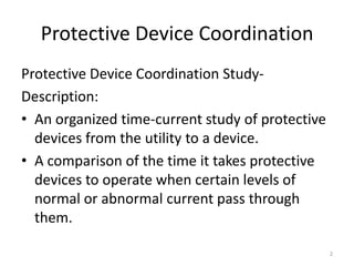
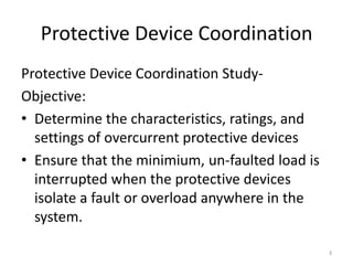
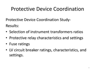

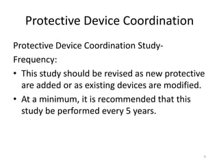
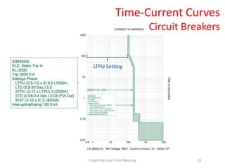
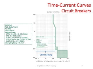
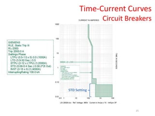
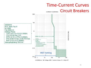


A protective device coordination study involves organizing the time-current characteristics of protective devices from the utility to downstream devices. The study determines device ratings, settings, and ensures minimum load is interrupted during faults while protecting devices. Results include instrument transformer ratios, relay settings, fuse ratings, and circuit breaker ratings. The study should be revised every 5 years or when devices are added or modified.


![protection of transmission lines[distance relay protection scheme]](https://cdn.slidesharecdn.com/ss_thumbnails/os-exe3-23-may2011-sr-i-776s21tr-lineprotection-120425095503-phpapp02-thumbnail.jpg?width=640&height=640&fit=bounds)


