Downloaded 122 times


![N-R Power Flow Solution
(0)
( )
( 1) ( ) ( ) 1 ( )
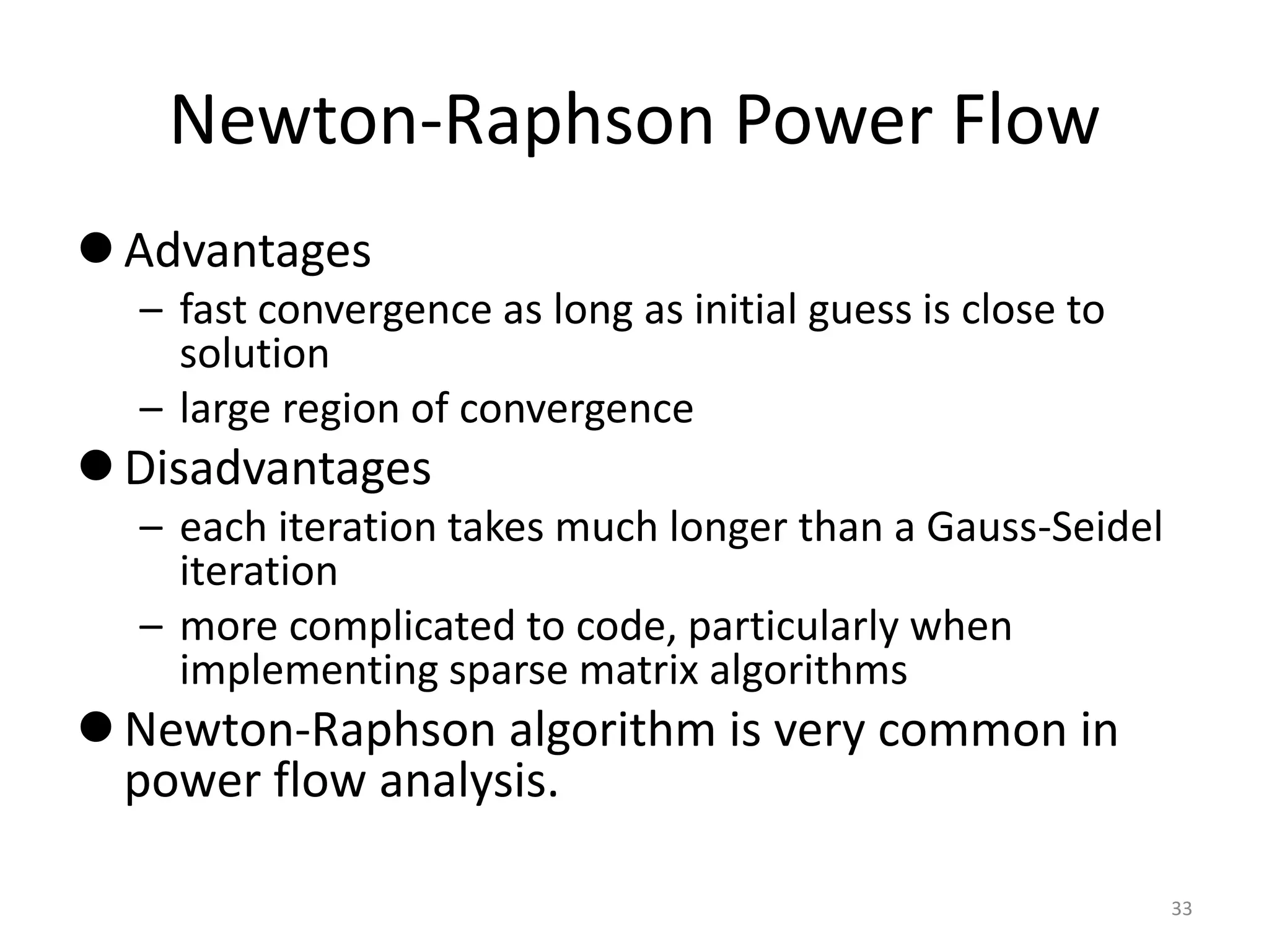
The power flow is solved using the same procedure
discussed previously for general equations:
For 0; make an initial guess of ,
While ( ) Do
[ ( )] ( )
1
End
v
v v v v
v
v v
x x
f x
x x J x f x
13](https://image.slidesharecdn.com/newtonraphsonmethod-150731142303-lva1-app6891/75/Newton-raphson-method-13-2048.jpg)


This document discusses power flow analysis and the Newton-Raphson power flow method. It provides details on setting up the power flow problem, including defining the power balance equations in terms of real and reactive power. It also describes calculating the Jacobian matrix and differentiating the power flow equations to populate the matrix. An example power flow case is presented on a two bus system to illustrate applying the Newton-Raphson method through multiple iterations to solve for the voltage magnitude and angle.


![Ece4762011 lect11[1]](https://cdn.slidesharecdn.com/ss_thumbnails/ece4762011lect111-170908023044-thumbnail.jpg?width=640&height=640&fit=bounds)


