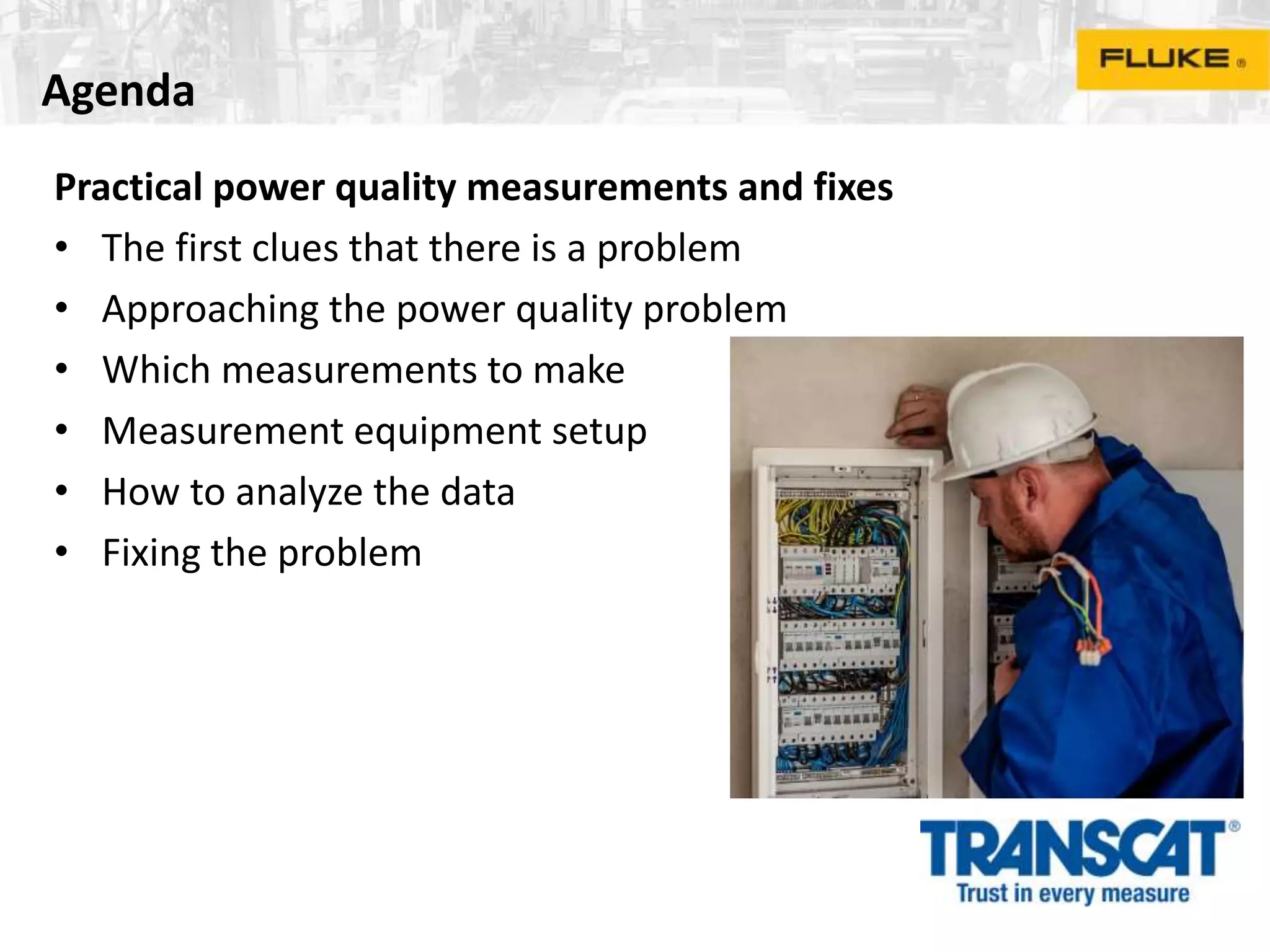
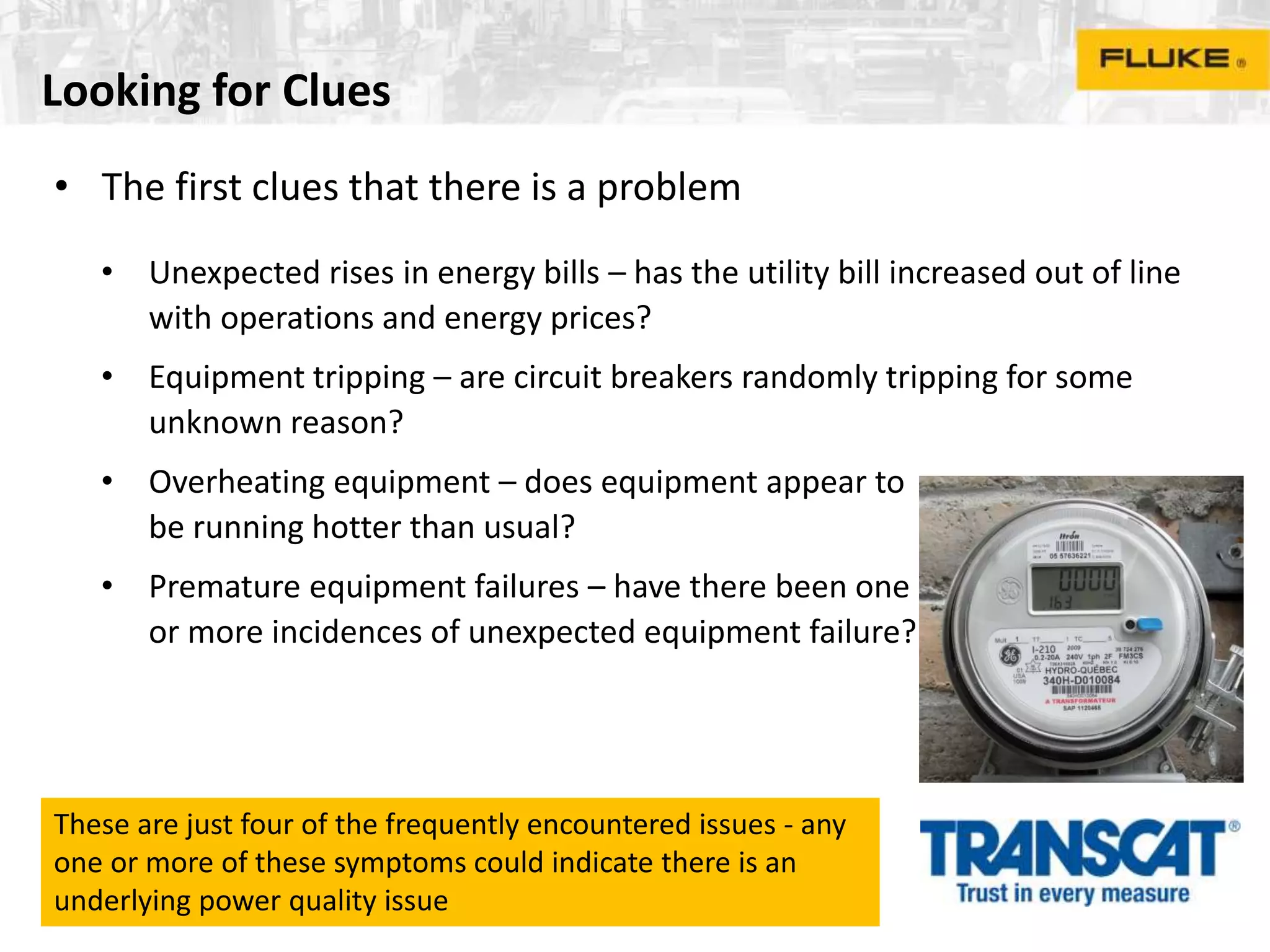
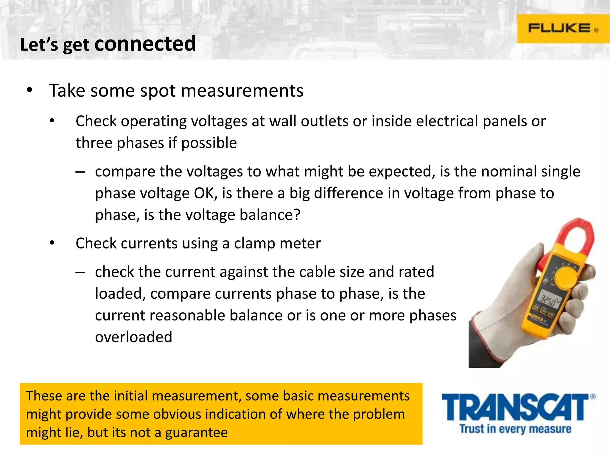
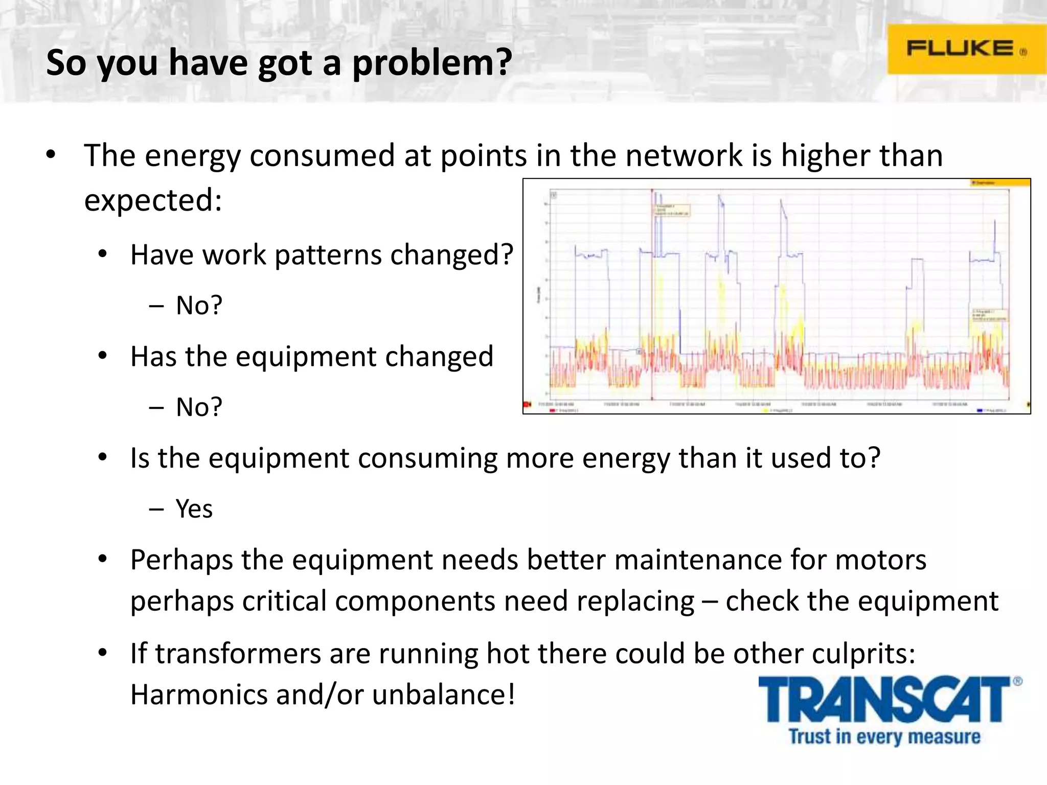
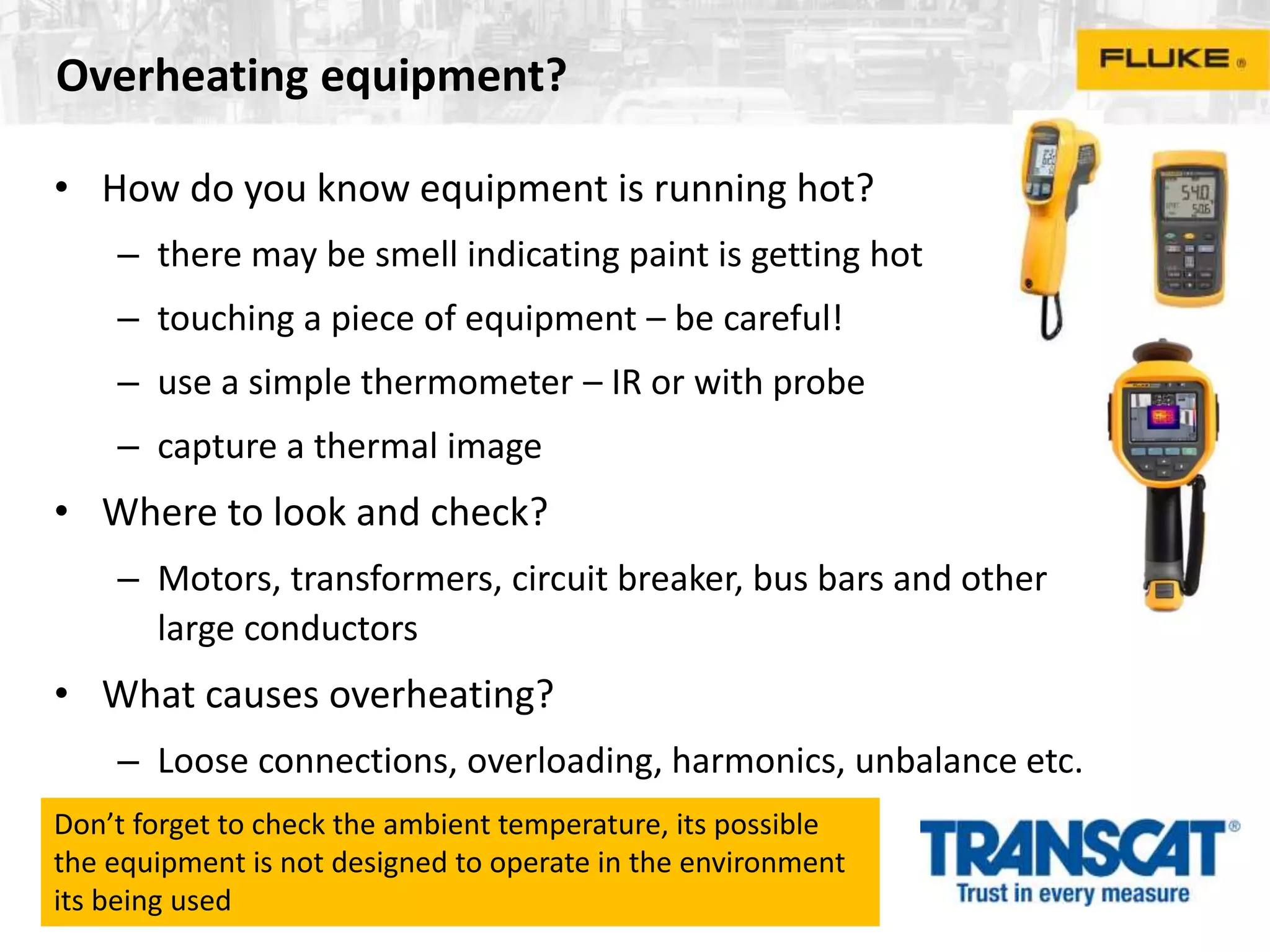
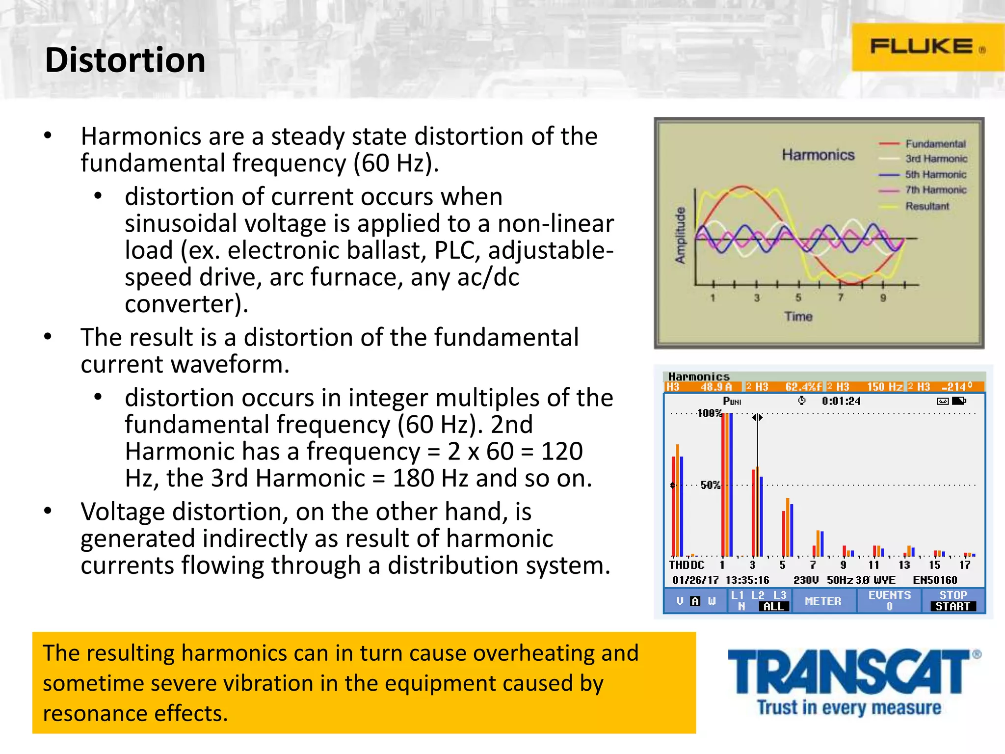
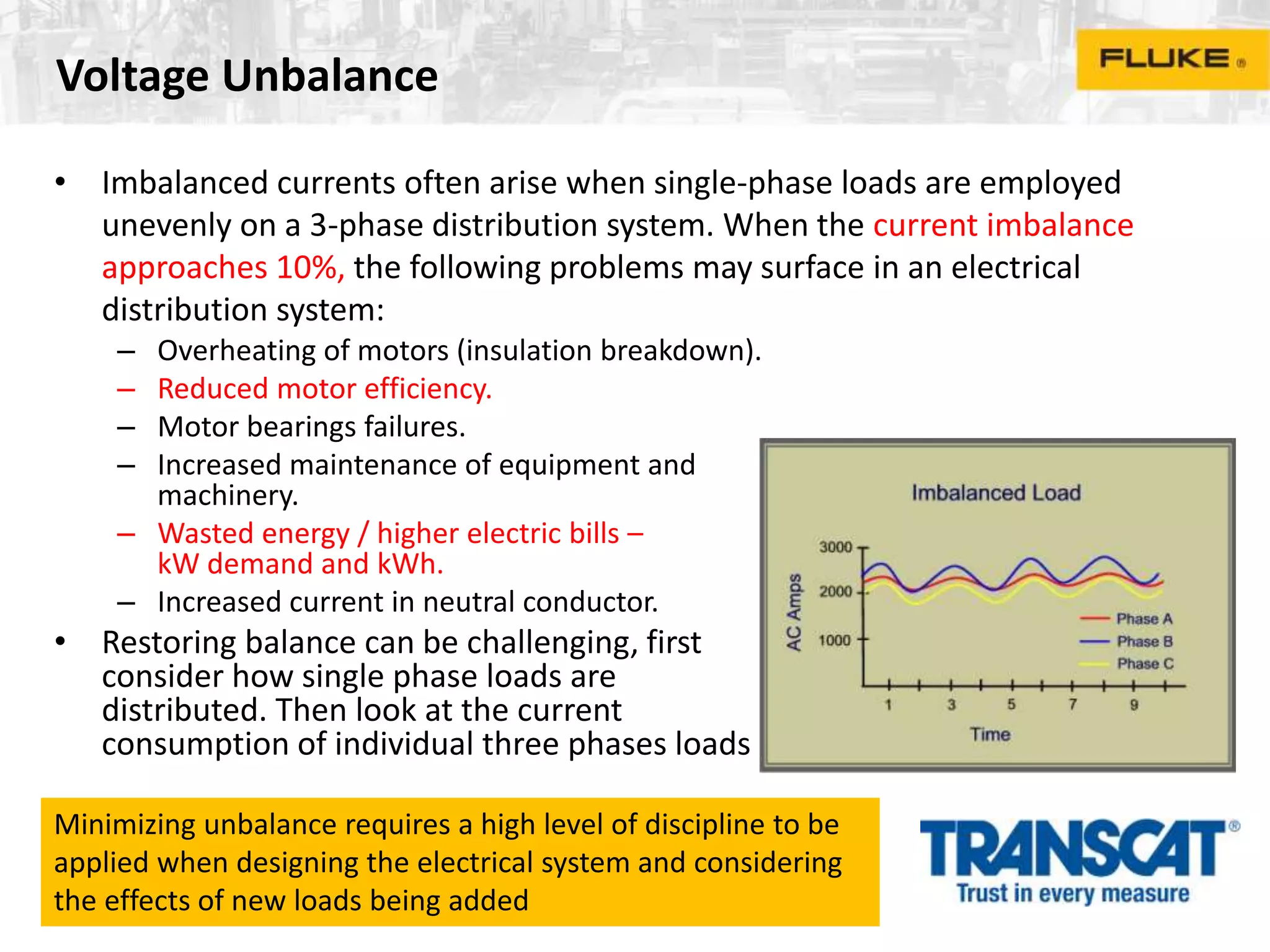
Practical power quality measurements and fixes
presented by
Frank Healy
Power Quality Product Marketing Manager
Agenda
Practical power quality measurements and fixes
• The first clues that there is a problem
• Approaching the power quality problem
• Which measurements to make
• Measurement equipment setup
• How to analyze the data
• Fixing the problem
Looking for Clues
• The first clues that there is a problem
• Unexpected rises in energy bills – has the utility bill increased out of line
with operations and energy prices?
• Equipment tripping – are circuit breakers randomly tripping for some
unknown reason?
• Overheating equipment – does equipment appear to
be running hotter than usual?
• Premature equipment failures – have there been one
or more incidences of unexpected equipment failure?
These are just four of the frequently encountered issues - any
one or more of these symptoms could indicate there is an
underlying power quality issue
What’s happening?
• Use your senses to survey the electrical system - eyes, ears and
smell
• See if new loads may have been added – have new machines, lighting or
other items been installed?
• See if any older equipment has been taken away of new wiring installed –
has equipment been decommissioned and removed?
• Check for changes in work processes or patterns – is the plant running
different shift or new processes introduced
• Listen for noisy motors – could bearings be in bad shape?
• Is there an acrid smell of overheating cables or transformers
• Is there an ozone smell caused by arching?
By using your senses its possible in some cases to get to the
source of the problem more quickly than considering the
whole electrical system
Let’s get connected
• Take some spot measurements
• Check operating voltages at wall outlets or inside electrical panels or
three phases if possible
– compare the voltages to what might be expected, is the nominal single
phase voltage OK, is there a big difference in voltage from phase to
phase, is the voltage balance?
• Check currents using a clamp meter
– check the current against the cable size and rated
loaded, compare currents phase to phase, is the
current reasonable balance or is one or more phases
overloaded
These are the initial measurement, some basic measurements
might provide some obvious indication of where the problem
might lie, but its not a guarantee
Unexpected utility bill?
• Log the power and energy at the utility meters for a few days,
compare the results to the expected or previous measurements
• Check where the largest feeders are in the system and log each
one over a few days, compare to the expected or previous
results
• Compare the energy consumption to the rating of the loads
connected
• Move downstream to the next largest load and continue to
move downstream until you build up a complete picture
Deciding what to measure is one of the most difficult decisions
when you have a power quality problem. Keep the logged
data for future comparisons
So you have got a problem?
• The energy consumed at points in the network is higher than
expected:
• Have work patterns changed?
– No?
• Has the equipment changed
– No?
• Is the equipment consuming more energy than it used to?
– Yes
• Perhaps the equipment needs better maintenance for motors
perhaps critical components need replacing – check the equipment
• If transformers are running hot there could be other culprits:
Harmonics and/or unbalance!
Equipment Tripping?
• Using a device that measures and log continuously check the
voltage and current
• Setup some nominal limits for the allowed voltage, typically
±10% of the expected voltage – consider values outside of this
range to be potential problems
• By considering voltage and current simultaneously its possible to
correlate if one is effecting the other – usually voltage drops by
some amount when current rises, such as when a load switches
on.
• Often a trip or dip might occur when the current is within
accepted levels – there are other sources causing dips
Discovering the reasons for equipment trips needs patience, it
doesn’t always happen when you expect it
Equipment Tripping?
• Other sources can be loads switching on other circuits
– large motors or transformers on an adjacent circuit an cause
unexpected dip where the current may not be changing at the load
• Another area to look at are the settings of the circuit breaker
– breakers sometimes have settings of delay or fault pickup to
ensure the breaker does no trip due to acceptable conditions – if
these settings are incorrect the breaker may trip accidentally
• Harmonics and unbalance
– behavior of breaker characteristics can be affected by distorted
voltage current and three phase unbalance
– basic expression of distortion is THD (total harmonic distortion)
These examples indicate its not always just about the voltage
and current and other parameters need to be considered
Overheating equipment?
• How do you know equipment is running hot?
– there may be smell indicating paint is getting hot
– touching a piece of equipment – be careful!
– use a simple thermometer – IR or with probe
– capture a thermal image
• Where to look and check?
– Motors, transformers, circuit breaker, bus bars and other
large conductors
• What causes overheating?
– Loose connections, overloading, harmonics, unbalance etc.
Don’t forget to check the ambient temperature, its possible
the equipment is not designed to operate in the environment
its being used
Overheating equipment?
• Tighten all the connections
– Ensure the bolts on the connections to the each piece of
equipment is tightened in accordance with the manufacturers
recommendation
– Compare the current drawn with the specification (as before)
– Use a power quality meter/analyzer to see if the distortion and or
unbalance exceeds normal levels
• voltage distortion >8%? - you have a possible problem
• voltage unbalance >2% at the service entrance or >3-4% at the load?
– you could have a problem
After tightening up recheck the temperatures once things have
cooled down
Distortion
• Harmonics are a steady state distortion of the
fundamental frequency (60 Hz).
• distortion of current occurs when
sinusoidal voltage is applied to a non-linear
load (ex. electronic ballast, PLC, adjustable-
speed drive, arc furnace, any ac/dc
converter).
• The result is a distortion of the fundamental
current waveform.
• distortion occurs in integer multiples of the
fundamental frequency (60 Hz). 2nd
Harmonic has a frequency = 2 x 60 = 120
Hz, the 3rd Harmonic = 180 Hz and so on.
• Voltage distortion, on the other hand, is
generated indirectly as result of harmonic
currents flowing through a distribution system.
The resulting harmonics can in turn cause overheating and
sometime severe vibration in the equipment caused by
resonance effects.
Voltage Unbalance
• Imbalanced currents often arise when single-phase loads are employed
unevenly on a 3-phase distribution system. When the current imbalance
approaches 10%, the following problems may surface in an electrical
distribution system:
– Overheating of motors (insulation breakdown).
– Reduced motor efficiency.
– Motor bearings failures.
– Increased maintenance of equipment and
machinery.
– Wasted energy / higher electric bills –
kW demand and kWh.
– Increased current in neutral conductor.
• Restoring balance can be challenging, first
consider how single phase loads are
distributed. Then look at the current
consumption of individual three phases loads
Minimizing unbalance requires a high level of discipline to be
applied when designing the electrical system and considering
the effects of new loads being added
Premature equipment failures
• Electrical equipment when used appropriately should run efficiently for years
• Discovering the reasons for premature equipment failures can be difficult:
– Is the quality of the equipment poor?
– Is it being misused? (wrong voltage, not suitable for application etc.)
– Is it caused by poor power quality?
• Eliminate the first two and then proceed with power quality benchmarking
– Check the key parameters:
• Dips and swells
• Harmonics
• Unbalance
If the power quality measurements show that the values are
being exceeded frequently it could be power quality is the
problem, now fix the problem.
Which measurements to make?
• Absolute basic requirements are:
– Voltage and current - power and power factor too hopefully
• Log over time to see the trends of these values to assist in correlating when problems
occur
– Voltage dips and swells without any gaps between measurements – spot checks
with hand held devices won’t do the job, even if they log the voltage very second
– Harmonic distortion – voltage and current distortion up to the 50th harmonic
(3,000 Hz), usually displayed as a bargraph
– Unbalance – voltage and current
• Knowing both helps discover why the unbalance might
be present
Using these basic measurements can discover many of the
possible power quality problems that might exist – there are
other possibilities for more advanced analysis
Measurement equipment set up?
• Connect the measurement equipment to the voltage (observing safety
requirements)
– Ensure that the right phase sequence is selected A-A, B-B, C-C, neutral etc.
• Connect the current measurement devices to the equipment
– Ensure that the right phase sequence is selected A-A, B-B, C-C, neutral etc.
– Observe the direction of any arrows on the
current devices – these should point to the
load (the equipment consuming current)
• Check the connections are correct, check
again, look at the readings, is power
positive, does power factor look correct?
Some instrument have the capability to compare what is being
measure and adjust automatically if an error is made
Measurement equipment set up?
• Select the correct operating voltage and frequency
– this matters as dips and swells are relative to this voltage.
• Chose the correct range for current measurement
– avoid being under or over range, ideally chose automatic ranging
• Chose the right circuit type – delta / wye as this could affect all the results
• Check the setting are correct, check
again, look at the readings, is power
positive, does power factor look correct?
Successful setup is vital to making successful measurements –
imagine measuring for two weeks and coming bck to invalid
results?
How to analyze the data?
• Take a look at any trend graphs or summaries on the instrument before
disconnection to see if you have useful results
– continue to measure if you don’t if possible
• Download the data to PC using the appropriate software
– this software should be able to provide graphical representations of logged data,
tables with dip/swell events along with dates and time those things occurred
• Normally you will need to share the data with others to develop an action
plan to fix the problem
– create reports that explain what happened when the measurements were made
– these can be some data with plain English explanations of you thoughts
– they can be paper or PDF documents, spreadsheets etc.
This part of the process is the opportunity to get to the real
root cause of the problem, creating reports allows sharing to
get other opinions and confirmation of the situation
Typical reports
Reports take many forms, pictures can really help explain
complex data and if the software is of reasonable quality it will
produce these with minimum effort.
How do I fix the problem?
• Dips and swells
– Size the conductors feeding the load that keep the voltage within acceptable
limits – national or local electrical codes advise of the conductor sizes for specific
current ratings
– Ensure your circuit breakers are setup correctly – correct current level, delay
setting etc.
– Install devices that alleviate the any dips – maintain the voltage during the dip
• constant voltage transformers, electronic dip compensators, UPS,
– Consider installing separate feeds for sensitive loads – ensure correct grounding
practices are applied to avoid ground loops
• Harmonics
• Unbalance
If the power quality measurements show that the values are
being exceeded frequently it could be power quality is the
problem, now fix the problem.
How do I fix the problem?
• Harmonics
– Firstly you will need to know the overall level of distortion and each contributory
harmonic
• THD (total harmonic distortion indicates the overall distortion)
• Each harmonic can be shown on a bar graph and the highest ones should be isolated in
a trend graph
• A list or table of harmonics can also be useful
– Once you have a picture of the distortion its time to consider fixing them
• This can be done by installing a filter, this can be at individual distorting loads or for the
overall circuit under consideration
• Once you have a filter, install it and then measure all over againg to show its
dong its job effctively
To get a suitable filter you should contact a filter manufacturer
and have them look at your data so they can come up with the
best alternatives
How do I fix the problem?
• Unbalance
– Firstly you will need to know the overall level of unbalance
• The acceptable level of unbalance is dependent on where you are measuring at the
service entrance unbalance should be <2%
• A rule of thumb is ‘the higher the power of the circuit the lower the unbalance’
– A first step to reduce unbalance is to ensure single phase loads are distributed
evenly over the three phases
• Check the larger single phase loads aren’t on one phase
– For higher power systems it might be necessary to install mitigation system which
are special sorts of transformer designed to balance the system
Reducing unbalance is important as its effects can be serious
causing damage to motors and causing overheating in
transformers and motors
Practical power quality measurements and fixes
Summary
• A methodical approach is required, consider each step along the way
• Retrace the steps if you’re not sure of something
• Listen to people affected by the problem, they can often help point out
conditions that are causing the problem
• Try and find historic data, if its not available make you first set of data the first
step in history for next time (yes, there probably will be a next time).
• Check and double check each step along the way
• Best practice suggests you should measure power quality as often as possible
to maintain reliability.
• Don’t leave the meter in a cupboard, have it connected somewhere always.
Maintaining good power quality makes sense, it will keep your
electrical system and in the long run save money by reducing
your energy bill
Practical Power Quality Measurements and Fixes Presented by Fluke and Transcat

Practical Power Quality Measurements and Fixes Presented by Fluke and Transcat

  • 1.
    Practical power qualitymeasurements and fixes presented by Frank Healy Power Quality Product Marketing Manager
  • 2.
    Agenda Practical power qualitymeasurements and fixes • The first clues that there is a problem • Approaching the power quality problem • Which measurements to make • Measurement equipment setup • How to analyze the data • Fixing the problem
  • 3.
    Looking for Clues •The first clues that there is a problem • Unexpected rises in energy bills – has the utility bill increased out of line with operations and energy prices? • Equipment tripping – are circuit breakers randomly tripping for some unknown reason? • Overheating equipment – does equipment appear to be running hotter than usual? • Premature equipment failures – have there been one or more incidences of unexpected equipment failure? These are just four of the frequently encountered issues - any one or more of these symptoms could indicate there is an underlying power quality issue
  • 4.
    What’s happening? • Useyour senses to survey the electrical system - eyes, ears and smell • See if new loads may have been added – have new machines, lighting or other items been installed? • See if any older equipment has been taken away of new wiring installed – has equipment been decommissioned and removed? • Check for changes in work processes or patterns – is the plant running different shift or new processes introduced • Listen for noisy motors – could bearings be in bad shape? • Is there an acrid smell of overheating cables or transformers • Is there an ozone smell caused by arching? By using your senses its possible in some cases to get to the source of the problem more quickly than considering the whole electrical system
  • 5.
    Let’s get connected •Take some spot measurements • Check operating voltages at wall outlets or inside electrical panels or three phases if possible – compare the voltages to what might be expected, is the nominal single phase voltage OK, is there a big difference in voltage from phase to phase, is the voltage balance? • Check currents using a clamp meter – check the current against the cable size and rated loaded, compare currents phase to phase, is the current reasonable balance or is one or more phases overloaded These are the initial measurement, some basic measurements might provide some obvious indication of where the problem might lie, but its not a guarantee
  • 6.
    Unexpected utility bill? •Log the power and energy at the utility meters for a few days, compare the results to the expected or previous measurements • Check where the largest feeders are in the system and log each one over a few days, compare to the expected or previous results • Compare the energy consumption to the rating of the loads connected • Move downstream to the next largest load and continue to move downstream until you build up a complete picture Deciding what to measure is one of the most difficult decisions when you have a power quality problem. Keep the logged data for future comparisons
  • 7.
    So you havegot a problem? • The energy consumed at points in the network is higher than expected: • Have work patterns changed? – No? • Has the equipment changed – No? • Is the equipment consuming more energy than it used to? – Yes • Perhaps the equipment needs better maintenance for motors perhaps critical components need replacing – check the equipment • If transformers are running hot there could be other culprits: Harmonics and/or unbalance!
  • 8.
    Equipment Tripping? • Usinga device that measures and log continuously check the voltage and current • Setup some nominal limits for the allowed voltage, typically ±10% of the expected voltage – consider values outside of this range to be potential problems • By considering voltage and current simultaneously its possible to correlate if one is effecting the other – usually voltage drops by some amount when current rises, such as when a load switches on. • Often a trip or dip might occur when the current is within accepted levels – there are other sources causing dips Discovering the reasons for equipment trips needs patience, it doesn’t always happen when you expect it
  • 9.
    Equipment Tripping? • Othersources can be loads switching on other circuits – large motors or transformers on an adjacent circuit an cause unexpected dip where the current may not be changing at the load • Another area to look at are the settings of the circuit breaker – breakers sometimes have settings of delay or fault pickup to ensure the breaker does no trip due to acceptable conditions – if these settings are incorrect the breaker may trip accidentally • Harmonics and unbalance – behavior of breaker characteristics can be affected by distorted voltage current and three phase unbalance – basic expression of distortion is THD (total harmonic distortion) These examples indicate its not always just about the voltage and current and other parameters need to be considered
  • 10.
    Overheating equipment? • Howdo you know equipment is running hot? – there may be smell indicating paint is getting hot – touching a piece of equipment – be careful! – use a simple thermometer – IR or with probe – capture a thermal image • Where to look and check? – Motors, transformers, circuit breaker, bus bars and other large conductors • What causes overheating? – Loose connections, overloading, harmonics, unbalance etc. Don’t forget to check the ambient temperature, its possible the equipment is not designed to operate in the environment its being used
  • 11.
    Overheating equipment? • Tightenall the connections – Ensure the bolts on the connections to the each piece of equipment is tightened in accordance with the manufacturers recommendation – Compare the current drawn with the specification (as before) – Use a power quality meter/analyzer to see if the distortion and or unbalance exceeds normal levels • voltage distortion >8%? - you have a possible problem • voltage unbalance >2% at the service entrance or >3-4% at the load? – you could have a problem After tightening up recheck the temperatures once things have cooled down
  • 12.
    Distortion • Harmonics area steady state distortion of the fundamental frequency (60 Hz). • distortion of current occurs when sinusoidal voltage is applied to a non-linear load (ex. electronic ballast, PLC, adjustable- speed drive, arc furnace, any ac/dc converter). • The result is a distortion of the fundamental current waveform. • distortion occurs in integer multiples of the fundamental frequency (60 Hz). 2nd Harmonic has a frequency = 2 x 60 = 120 Hz, the 3rd Harmonic = 180 Hz and so on. • Voltage distortion, on the other hand, is generated indirectly as result of harmonic currents flowing through a distribution system. The resulting harmonics can in turn cause overheating and sometime severe vibration in the equipment caused by resonance effects.
  • 13.
    Voltage Unbalance • Imbalancedcurrents often arise when single-phase loads are employed unevenly on a 3-phase distribution system. When the current imbalance approaches 10%, the following problems may surface in an electrical distribution system: – Overheating of motors (insulation breakdown). – Reduced motor efficiency. – Motor bearings failures. – Increased maintenance of equipment and machinery. – Wasted energy / higher electric bills – kW demand and kWh. – Increased current in neutral conductor. • Restoring balance can be challenging, first consider how single phase loads are distributed. Then look at the current consumption of individual three phases loads Minimizing unbalance requires a high level of discipline to be applied when designing the electrical system and considering the effects of new loads being added
  • 14.
    Premature equipment failures •Electrical equipment when used appropriately should run efficiently for years • Discovering the reasons for premature equipment failures can be difficult: – Is the quality of the equipment poor? – Is it being misused? (wrong voltage, not suitable for application etc.) – Is it caused by poor power quality? • Eliminate the first two and then proceed with power quality benchmarking – Check the key parameters: • Dips and swells • Harmonics • Unbalance If the power quality measurements show that the values are being exceeded frequently it could be power quality is the problem, now fix the problem.
  • 15.
    Which measurements tomake? • Absolute basic requirements are: – Voltage and current - power and power factor too hopefully • Log over time to see the trends of these values to assist in correlating when problems occur – Voltage dips and swells without any gaps between measurements – spot checks with hand held devices won’t do the job, even if they log the voltage very second – Harmonic distortion – voltage and current distortion up to the 50th harmonic (3,000 Hz), usually displayed as a bargraph – Unbalance – voltage and current • Knowing both helps discover why the unbalance might be present Using these basic measurements can discover many of the possible power quality problems that might exist – there are other possibilities for more advanced analysis
  • 16.
    Measurement equipment setup? • Connect the measurement equipment to the voltage (observing safety requirements) – Ensure that the right phase sequence is selected A-A, B-B, C-C, neutral etc. • Connect the current measurement devices to the equipment – Ensure that the right phase sequence is selected A-A, B-B, C-C, neutral etc. – Observe the direction of any arrows on the current devices – these should point to the load (the equipment consuming current) • Check the connections are correct, check again, look at the readings, is power positive, does power factor look correct? Some instrument have the capability to compare what is being measure and adjust automatically if an error is made
  • 17.
    Measurement equipment setup? • Select the correct operating voltage and frequency – this matters as dips and swells are relative to this voltage. • Chose the correct range for current measurement – avoid being under or over range, ideally chose automatic ranging • Chose the right circuit type – delta / wye as this could affect all the results • Check the setting are correct, check again, look at the readings, is power positive, does power factor look correct? Successful setup is vital to making successful measurements – imagine measuring for two weeks and coming bck to invalid results?
  • 18.
    How to analyzethe data? • Take a look at any trend graphs or summaries on the instrument before disconnection to see if you have useful results – continue to measure if you don’t if possible • Download the data to PC using the appropriate software – this software should be able to provide graphical representations of logged data, tables with dip/swell events along with dates and time those things occurred • Normally you will need to share the data with others to develop an action plan to fix the problem – create reports that explain what happened when the measurements were made – these can be some data with plain English explanations of you thoughts – they can be paper or PDF documents, spreadsheets etc. This part of the process is the opportunity to get to the real root cause of the problem, creating reports allows sharing to get other opinions and confirmation of the situation
  • 19.
    Typical reports Reports takemany forms, pictures can really help explain complex data and if the software is of reasonable quality it will produce these with minimum effort.
  • 20.
    How do Ifix the problem? • Dips and swells – Size the conductors feeding the load that keep the voltage within acceptable limits – national or local electrical codes advise of the conductor sizes for specific current ratings – Ensure your circuit breakers are setup correctly – correct current level, delay setting etc. – Install devices that alleviate the any dips – maintain the voltage during the dip • constant voltage transformers, electronic dip compensators, UPS, – Consider installing separate feeds for sensitive loads – ensure correct grounding practices are applied to avoid ground loops • Harmonics • Unbalance If the power quality measurements show that the values are being exceeded frequently it could be power quality is the problem, now fix the problem.
  • 21.
    How do Ifix the problem? • Harmonics – Firstly you will need to know the overall level of distortion and each contributory harmonic • THD (total harmonic distortion indicates the overall distortion) • Each harmonic can be shown on a bar graph and the highest ones should be isolated in a trend graph • A list or table of harmonics can also be useful – Once you have a picture of the distortion its time to consider fixing them • This can be done by installing a filter, this can be at individual distorting loads or for the overall circuit under consideration • Once you have a filter, install it and then measure all over againg to show its dong its job effctively To get a suitable filter you should contact a filter manufacturer and have them look at your data so they can come up with the best alternatives
  • 22.
    How do Ifix the problem? • Unbalance – Firstly you will need to know the overall level of unbalance • The acceptable level of unbalance is dependent on where you are measuring at the service entrance unbalance should be <2% • A rule of thumb is ‘the higher the power of the circuit the lower the unbalance’ – A first step to reduce unbalance is to ensure single phase loads are distributed evenly over the three phases • Check the larger single phase loads aren’t on one phase – For higher power systems it might be necessary to install mitigation system which are special sorts of transformer designed to balance the system Reducing unbalance is important as its effects can be serious causing damage to motors and causing overheating in transformers and motors
  • 23.
    Practical power qualitymeasurements and fixes Summary • A methodical approach is required, consider each step along the way • Retrace the steps if you’re not sure of something • Listen to people affected by the problem, they can often help point out conditions that are causing the problem • Try and find historic data, if its not available make you first set of data the first step in history for next time (yes, there probably will be a next time). • Check and double check each step along the way • Best practice suggests you should measure power quality as often as possible to maintain reliability. • Don’t leave the meter in a cupboard, have it connected somewhere always. Maintaining good power quality makes sense, it will keep your electrical system and in the long run save money by reducing your energy bill