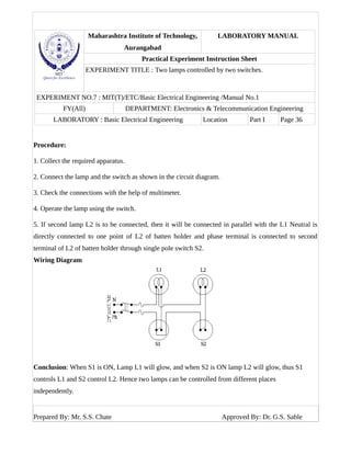
Maharashtra Institute of Technology,
Aurangabad
LABORATORY MANUAL
Practical Experiment Instruction Sheet
EXPERIMENT TITLE : Two lamps controlled by two switches.
EXPERIMENT NO.7: MIT(T)/ETC/Basic Electrical Engineering /Manual No.1
FY(All) DEPARTMENT: Electronics & Telecommunication Engineering
LABORATORY : Basic Electrical Engineering Location Part I Page 35
Aim: Two lamps controlled by two switches.
Apparatus:
1. Wires 2. Switches( SPST) 3. Plugs and Sockets 4. Fuses 5.Lamps 6. Multimeter
Theory :
In a house, there are many electrical appliances that have to run independent of each other. If one
appliance is turned on or off it should not affect the other appliances. This is not possible if all the
appliances were connected in a series arrangement as there would be one switch that either switches all
of them on or off. When appliances are connected in a parallel arrangement, each of them can be put
on and off independently. This is a feature that is essential in a house's wiring.
Also, if the appliances were wired in series, the potential difference across each appliance
would vary depending on the resistance of the appliance. This would make it very difficult to provide
the right power to flow through the appliances. When house wiring is done in parallel this problem
does not arise as the potential difference across each appliance is the same and equal to the potential
difference being provided by the power company. Adding or removing device has no effect on the
others devices because the Voltage in parallel circuit is same but the current is different. Any number
of devices can be added in this kind of circuit, simply by extending the phase and neutral conductors to
other devices.
In this experiment two lamps are connected in parallel combination. Each lamp is provided
a switch to ON and OFF the lamps.
Prepared By: Mr. S.S. Chate Approved By: Dr. G.S. Sable
Maharashtra Institute of Technology,
Aurangabad
LABORATORY MANUAL
Practical Experiment Instruction Sheet
EXPERIMENT TITLE : Two lamps controlled by two switches.
EXPERIMENT NO.7 : MIT(T)/ETC/Basic Electrical Engineering /Manual No.1
FY(All) DEPARTMENT: Electronics & Telecommunication Engineering
LABORATORY : Basic Electrical Engineering Location Part I Page 36
Procedure:
1. Collect the required apparatus.
2. Connect the lamp and the switch as shown in the circuit diagram.
3. Check the connections with the help of multimeter.
4. Operate the lamp using the switch.
5. If second lamp L2 is to be connected, then it will be connected in parallel with the L1 Neutral is
directly connected to one point of L2 of batten holder and phase terminal is connected to second
terminal of L2 of batten holder through single pole switch S2.
Wiring Diagram
Conclusion: When S1 is ON, Lamp L1 will glow, and when S2 is ON lamp L2 will glow, thus S1
controls L1 and S2 control L2. Hence two lamps can be controlled from different places
independently.
Prepared By: Mr. S.S. Chate Approved By: Dr. G.S. Sable

Experiment no. 7

  • 1.
    Maharashtra Institute ofTechnology, Aurangabad LABORATORY MANUAL Practical Experiment Instruction Sheet EXPERIMENT TITLE : Two lamps controlled by two switches. EXPERIMENT NO.7: MIT(T)/ETC/Basic Electrical Engineering /Manual No.1 FY(All) DEPARTMENT: Electronics & Telecommunication Engineering LABORATORY : Basic Electrical Engineering Location Part I Page 35 Aim: Two lamps controlled by two switches. Apparatus: 1. Wires 2. Switches( SPST) 3. Plugs and Sockets 4. Fuses 5.Lamps 6. Multimeter Theory : In a house, there are many electrical appliances that have to run independent of each other. If one appliance is turned on or off it should not affect the other appliances. This is not possible if all the appliances were connected in a series arrangement as there would be one switch that either switches all of them on or off. When appliances are connected in a parallel arrangement, each of them can be put on and off independently. This is a feature that is essential in a house's wiring. Also, if the appliances were wired in series, the potential difference across each appliance would vary depending on the resistance of the appliance. This would make it very difficult to provide the right power to flow through the appliances. When house wiring is done in parallel this problem does not arise as the potential difference across each appliance is the same and equal to the potential difference being provided by the power company. Adding or removing device has no effect on the others devices because the Voltage in parallel circuit is same but the current is different. Any number of devices can be added in this kind of circuit, simply by extending the phase and neutral conductors to other devices. In this experiment two lamps are connected in parallel combination. Each lamp is provided a switch to ON and OFF the lamps. Prepared By: Mr. S.S. Chate Approved By: Dr. G.S. Sable
  • 2.
    Maharashtra Institute ofTechnology, Aurangabad LABORATORY MANUAL Practical Experiment Instruction Sheet EXPERIMENT TITLE : Two lamps controlled by two switches. EXPERIMENT NO.7 : MIT(T)/ETC/Basic Electrical Engineering /Manual No.1 FY(All) DEPARTMENT: Electronics & Telecommunication Engineering LABORATORY : Basic Electrical Engineering Location Part I Page 36 Procedure: 1. Collect the required apparatus. 2. Connect the lamp and the switch as shown in the circuit diagram. 3. Check the connections with the help of multimeter. 4. Operate the lamp using the switch. 5. If second lamp L2 is to be connected, then it will be connected in parallel with the L1 Neutral is directly connected to one point of L2 of batten holder and phase terminal is connected to second terminal of L2 of batten holder through single pole switch S2. Wiring Diagram Conclusion: When S1 is ON, Lamp L1 will glow, and when S2 is ON lamp L2 will glow, thus S1 controls L1 and S2 control L2. Hence two lamps can be controlled from different places independently. Prepared By: Mr. S.S. Chate Approved By: Dr. G.S. Sable