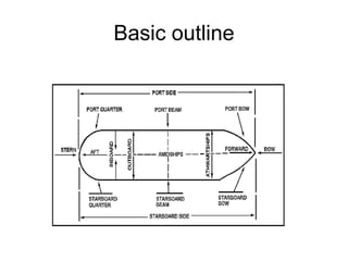
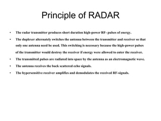
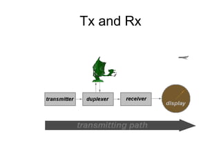
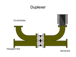
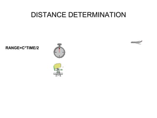
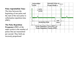
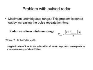
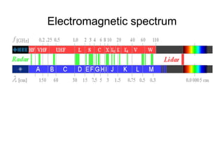
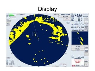
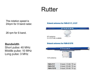
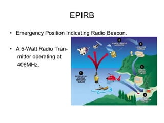
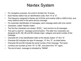
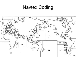
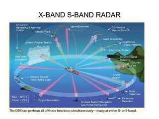
RADIO DETECTION AND RANGING
NAME: SHAHBAAZ LOKHANDWALA
B.TECH ECE V –SEM.
UNDER THE GUIDENCE OF DEEPIKA BANSAL
AGARWAL BUILDERS GROUP.LTD
INDIAN COAST GUARD SHIP -202
Classified Name
• 1A1-OIL REC-HELI DK (SHF)-FIFI-DYNPOS AUTS-Eo-SF-CRANE-ICS.
• 1A1 - Vessel for which periodical surveys are stipulated in relation to special (main)
periodical survey intervals of 5 years.
• OILREC - Vessel for occasional handling, storage and transportation of oil with flash
point below 60ºC recovered from a spill of oil in emergency situations.
• HELIDK-Helicopter Deck.
• DYNPOS Vessel with dynamic positioning systems
• E0 - Machinery of craft fitted with instrumentation and automation equipment
• SF - Implies classification of stability and floatability
• CRANE - Vessel with permanent cranes, when lifting operations are not a main
purpose.
• ICS - Integrated computer system.
Basic outline
Principle of RADAR
• The radar transmitter produces short duration high-power RF- pulses of energy.
• The duplexer alternately switches the antenna between the transmitter and receiver so that
only one antenna need be used. This switching is necessary because the high-power pulses
of the transmitter would destroy the receiver if energy were allowed to enter the receiver.
• The transmitted pulses are radiated into space by the antenna as an electromagnetic wave.
• The antenna receives the back scattered echo signals.
• The hypersensitive receiver amplifies and demodulates the received RF-signals.
Tx and Rx
Duplexer
TO ANTENNA
TRANSMITTER
RECIEVER
DISTANCE DETERMINATION
RANGE=C*TIME/2
Pulse repeatation Time:
The time between the
beginning of one pulse and
the start of the next pulse is
called pulse-repetition time
(PRT).
The Pulse Repetition
Frequency (PRF) of the
radar system is the number of
pulses that are transmitted
per second. They both are
inversely propotional
Problem with pulsed radar
• Maximum unambiguous range.: This problem is sorted
out by increasing the pulse repeatation time.
Radar waveform minimum range
Where Is the Pulse width.
A typical value of 1 µs for the pulse width of short range radar corresponds to
a minimum range of about 150 m.
Electromagnetic spectrum
Display
Rutter
The rotation speed is
24rpm for X band radar.
26 rpm for S band.
EPIRB
• Emergency Position Indicating Radio Beacon.
• A 5-Watt Radio Tran-
mitter operating at
406MHz.
Navtex System
• For navigation purposes, the world is divided into 16 areas.
• Each Navtex station has an identification code, from “A” to “Z”.
• The frequency assigned to Navtex are 518 kHz and another (490 or 4209.5 kHz), and
many stations exist in the same service coverage.
• For automatic identification of messages, each message starts with nine control
• characters, called “Header codes”.
• The first five characters are always “ZCZC_“ and common to all messages.
• This part is used for message synchronization. The latter four characters are
designed as B1, B2, B3 and B4 indicate origin, category and serial number of the
message.
• Character B1 is the identification letter of the Navtex station “A” thru “Z”.
• Character B2 indicates the type of message. “A” thru “Z”, as listed below.
• Character B3 and B4 indicate the serial number of the message. The serial
• numbers are counted up from “01” to “99”, and starts from “01” again.
• The end of each message is indicated by “NNNN”.
Navtex Coding
X-BAND S-BAND RADAR
Thank you

RADAR X band

  • 1.
    RADIO DETECTION ANDRANGING NAME: SHAHBAAZ LOKHANDWALA B.TECH ECE V –SEM. UNDER THE GUIDENCE OF DEEPIKA BANSAL
  • 2.
    AGARWAL BUILDERS GROUP.LTD INDIANCOAST GUARD SHIP -202
  • 3.
    Classified Name • 1A1-OILREC-HELI DK (SHF)-FIFI-DYNPOS AUTS-Eo-SF-CRANE-ICS. • 1A1 - Vessel for which periodical surveys are stipulated in relation to special (main) periodical survey intervals of 5 years. • OILREC - Vessel for occasional handling, storage and transportation of oil with flash point below 60ºC recovered from a spill of oil in emergency situations. • HELIDK-Helicopter Deck. • DYNPOS Vessel with dynamic positioning systems • E0 - Machinery of craft fitted with instrumentation and automation equipment • SF - Implies classification of stability and floatability • CRANE - Vessel with permanent cranes, when lifting operations are not a main purpose. • ICS - Integrated computer system.
  • 4.
  • 5.
    Principle of RADAR •The radar transmitter produces short duration high-power RF- pulses of energy. • The duplexer alternately switches the antenna between the transmitter and receiver so that only one antenna need be used. This switching is necessary because the high-power pulses of the transmitter would destroy the receiver if energy were allowed to enter the receiver. • The transmitted pulses are radiated into space by the antenna as an electromagnetic wave. • The antenna receives the back scattered echo signals. • The hypersensitive receiver amplifies and demodulates the received RF-signals.
  • 6.
  • 7.
  • 8.
  • 9.
    Pulse repeatation Time: Thetime between the beginning of one pulse and the start of the next pulse is called pulse-repetition time (PRT). The Pulse Repetition Frequency (PRF) of the radar system is the number of pulses that are transmitted per second. They both are inversely propotional
  • 10.
    Problem with pulsedradar • Maximum unambiguous range.: This problem is sorted out by increasing the pulse repeatation time. Radar waveform minimum range Where Is the Pulse width. A typical value of 1 µs for the pulse width of short range radar corresponds to a minimum range of about 150 m.
  • 11.
  • 12.
  • 13.
    Rutter The rotation speedis 24rpm for X band radar. 26 rpm for S band.
  • 14.
    EPIRB • Emergency PositionIndicating Radio Beacon. • A 5-Watt Radio Tran- mitter operating at 406MHz.
  • 15.
    Navtex System • Fornavigation purposes, the world is divided into 16 areas. • Each Navtex station has an identification code, from “A” to “Z”. • The frequency assigned to Navtex are 518 kHz and another (490 or 4209.5 kHz), and many stations exist in the same service coverage. • For automatic identification of messages, each message starts with nine control • characters, called “Header codes”. • The first five characters are always “ZCZC_“ and common to all messages. • This part is used for message synchronization. The latter four characters are designed as B1, B2, B3 and B4 indicate origin, category and serial number of the message. • Character B1 is the identification letter of the Navtex station “A” thru “Z”. • Character B2 indicates the type of message. “A” thru “Z”, as listed below. • Character B3 and B4 indicate the serial number of the message. The serial • numbers are counted up from “01” to “99”, and starts from “01” again. • The end of each message is indicated by “NNNN”.
  • 16.
  • 17.
  • 18.