Download to read offline

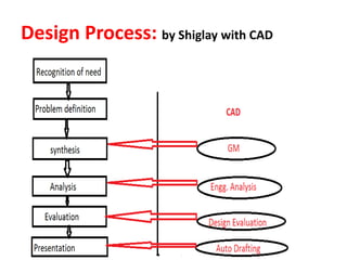
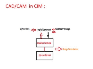
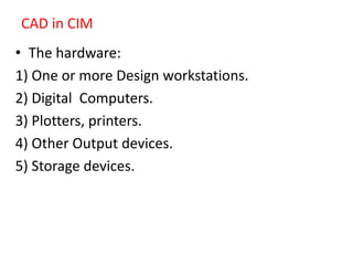
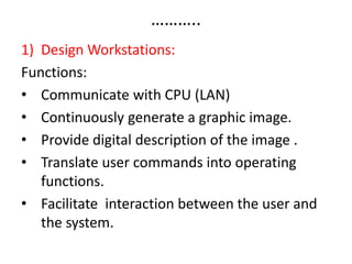
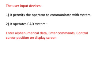
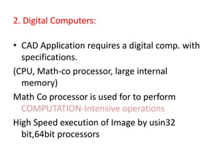
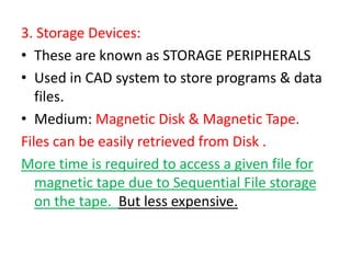


1. CAD/CAM systems integrate computer-aided design with computer-aided manufacturing to improve the design and production processes. 2. Key components of CAD systems include design workstations, digital computers, storage devices, and output devices like printers and plotters. 3. CAM systems aid in manufacturing planning and control through applications like computer-aided process planning, computer numerical control part programming, and cost estimating.